Week 9 - Project - Master Section Development
Aim: Creation of B-Pillar using Class A-Surface and master sections and performing draft analysis.
Description:
The B-pillar is the post between the front and back seat doors of a sedan/ SUV, connecting the roof to the body.
The A pillar is the first post connecting the roof and body at the windshield. The B-Pillar is typically a closed steel structure welded at the bottom to the car's rocker panel and floorpan, as well as on the top to the roof rail or panel. This pillar provides structural support for the vehicle's roof panel and is designed for latching the front door and mounting the hinges for the rear doors. All successive posts/ pillars follow the alphabet B,C, even D in order.
Step involved in creation of Tooling Axis:
Creation of Main Tooling Axis:
1. The master section of the locators is extarcted.
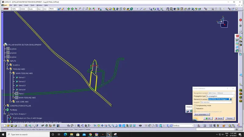
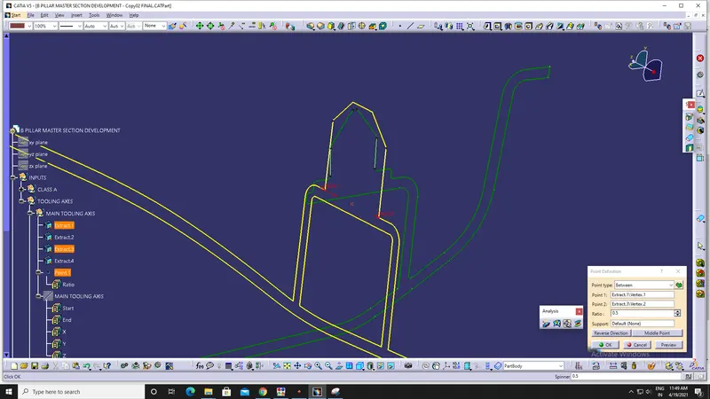
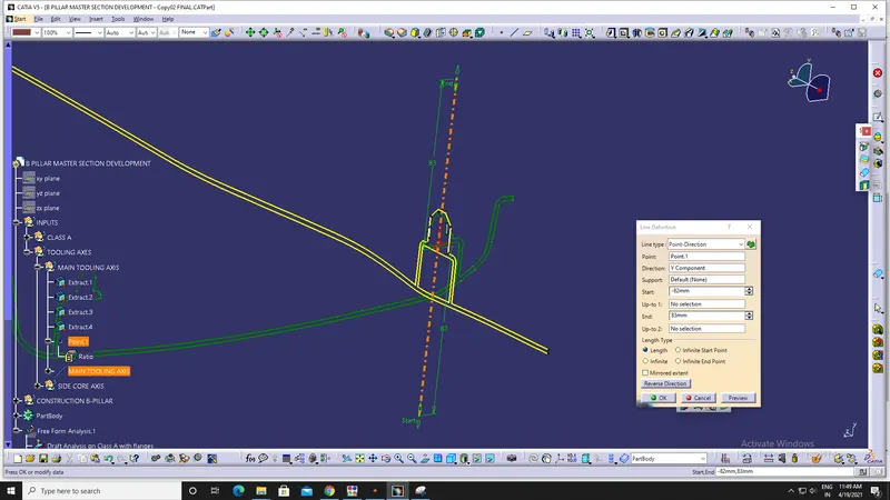
2. Point is created in between and a line is drawn using 'Point-Direction' option, which is main tooling axis.
Steps involved in analyzing Class A-surface and creating flanges according to given master section:
1. Check whether the given Class A-surface is of good quality (by applying boundary to the surface). There should not be void patches on the surface, if so then the surface is of bad quality.
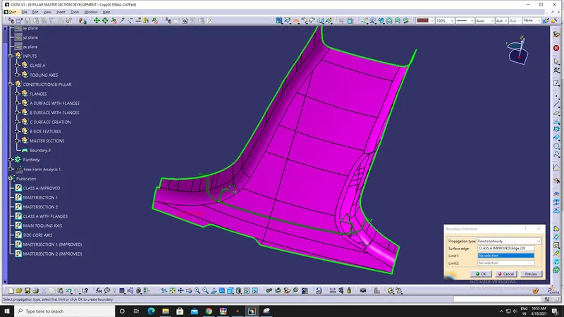
2. Flanges at the side of the Class-A surface are created as per the master section.
The edge of the Class A is extraced and then smooth curve is applied (to avoid creation of patches while using sweep).
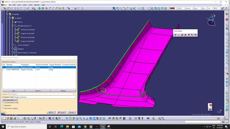
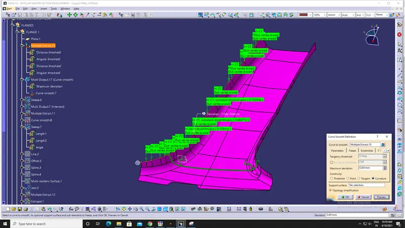
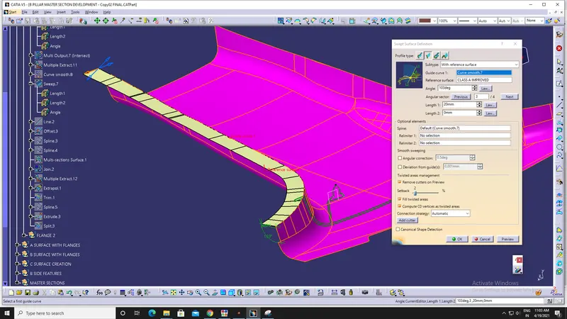
3. Sweep along draft direction is used to create flange and angle shoulb be in such a way that when flange is created it should meet the master section.
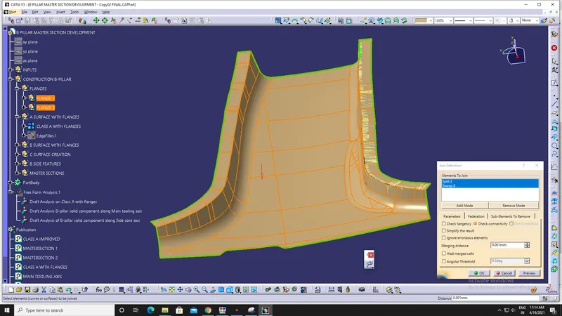
4. The flange created is offset so that it can meet the master section and is trimmed with A-surface and finally joined.
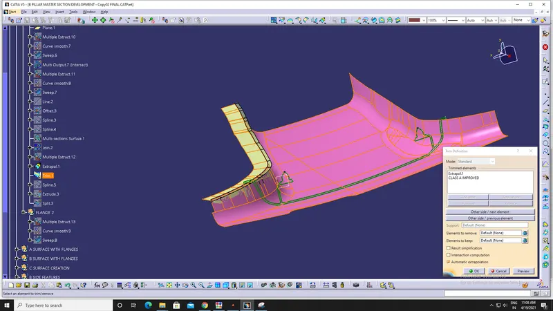
Now, the flange created is meeting master section.
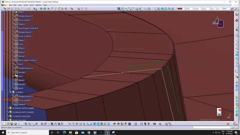
5 There is extra portion on class A-surface which is removed using split option
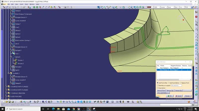
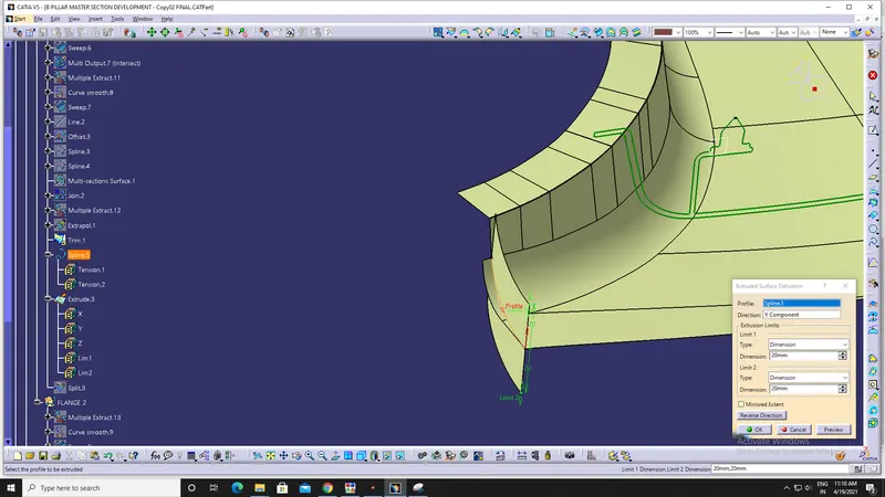
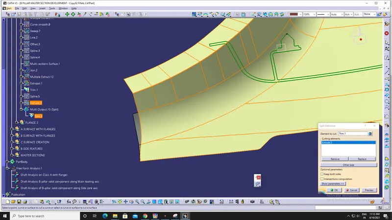
6. same steps should be followed on the other side to create flange on other side.
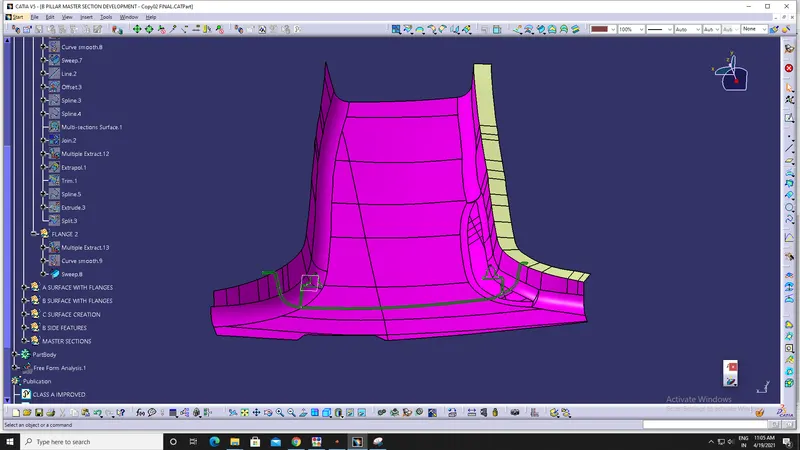
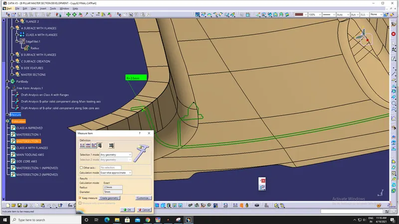
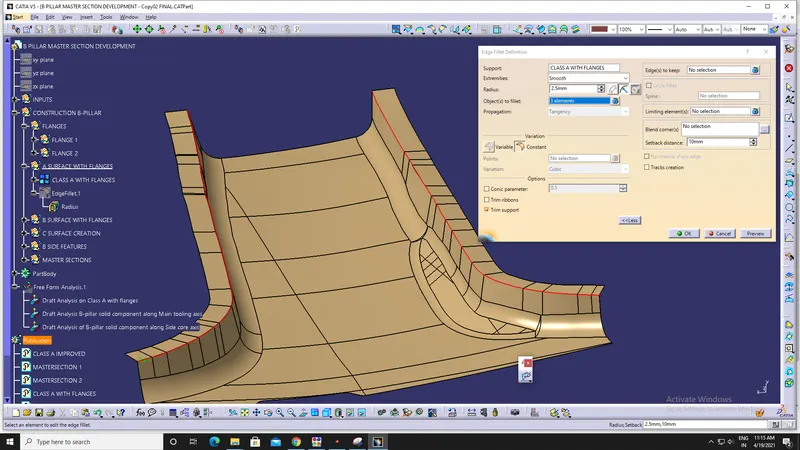
7. Now, Join it with the surface with one flange and provide fillet of 2.5mm (measured from master section)
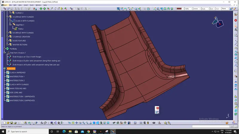
Steps involved in creation of Class B-Surface:
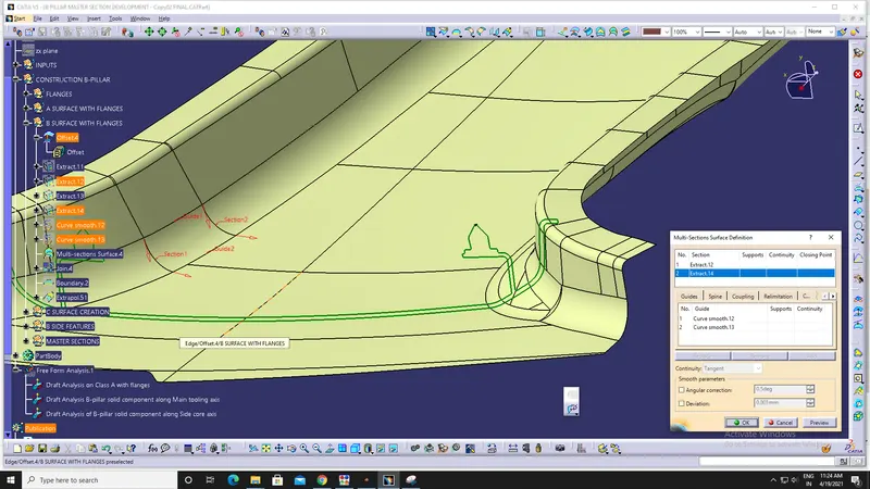
1. Offset the Surface with falnges to a distance of 2mm (from master section), but there is open patch created.
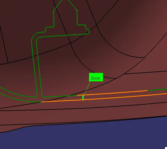
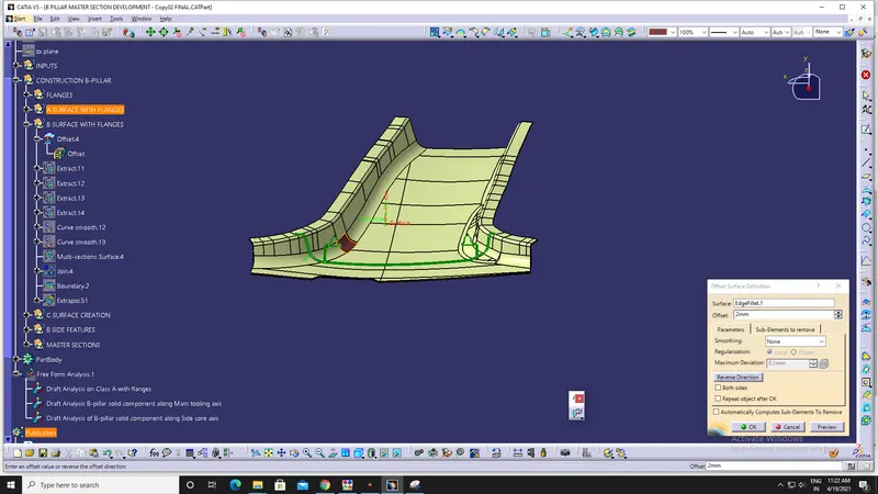
2. The open patch created is solved by extracting the edge, giving smooth curve and then applying multi section surface so that a close surface is created. Then, join it with surface.
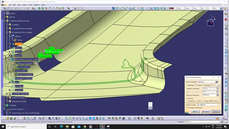
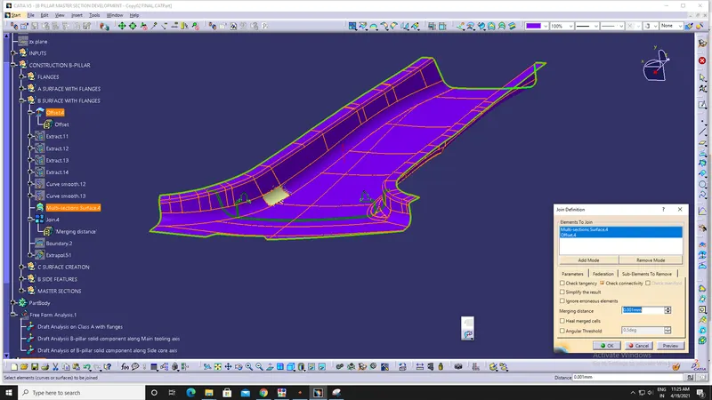
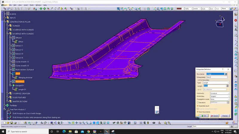
3. Extrapolate whole B-surface (in all direction), so that it can be trimmed with C-surface.
Steps involved in creation of Class C-Surface:
1. Extract the edges from the Class A-surface with flanges & provide smooth curve.
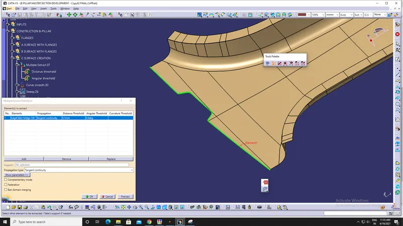
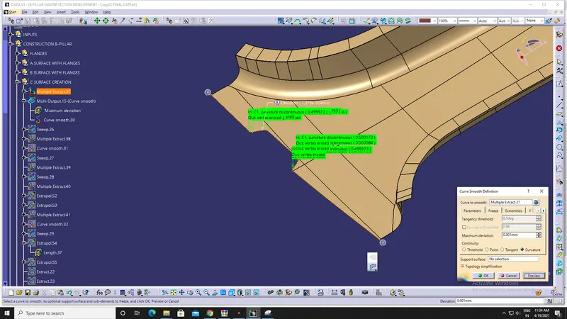
2. Sweep the smooth curves (at 3 degrees) along the main tooling axis.
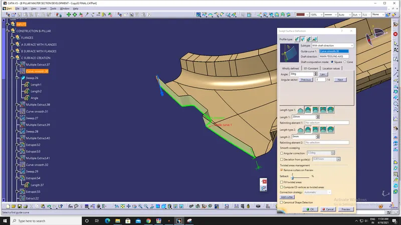
But, at the side the surface is extrapolated and sweeped (to avoid trimming of Class-A surface).
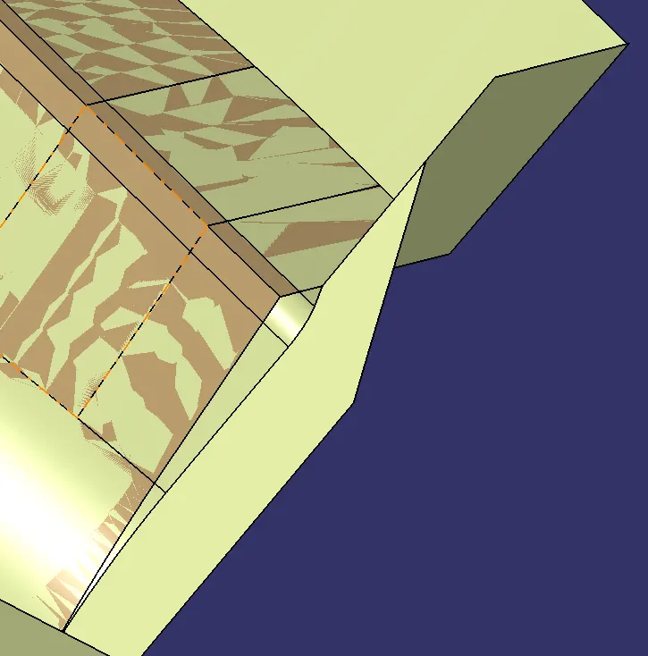
Above steps are followed until every edge is sweeped. Then trim the extra portions.
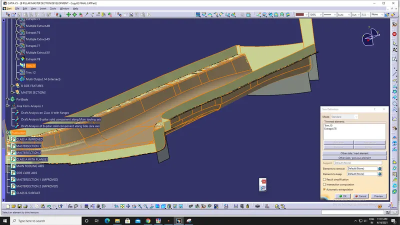
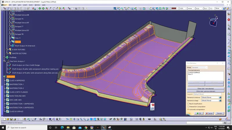
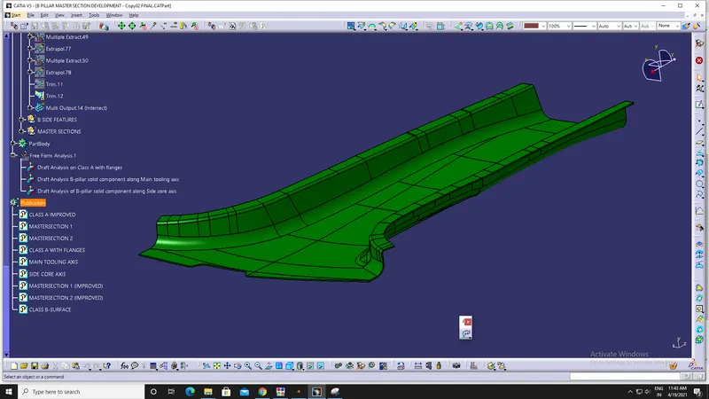
3. Trim the C-surface with Class B-surface.
Steps involved in creation of Solid component:
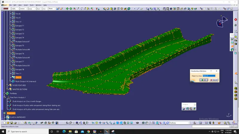
1. Changing the window from "Generative shape design" to "Part design" and choose "Close Surface" from "Surface based features" toolbar.
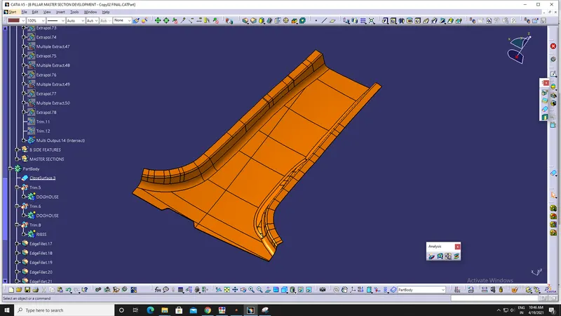
2. Selecting Class C-Surface as "Object to Close" and solid part is created.
Steps involved in creation of B-side features:
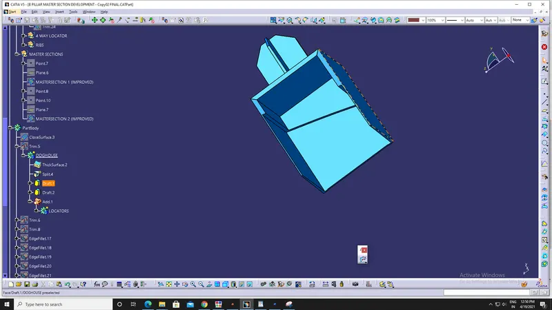
a. Doghouse:
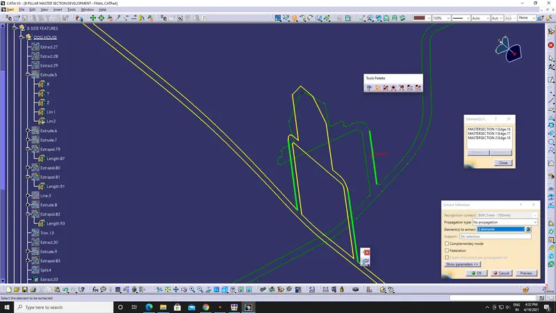
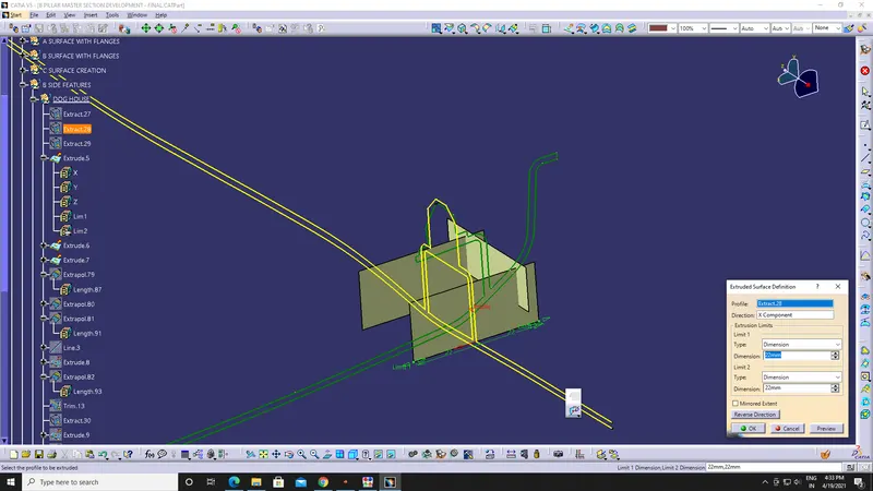
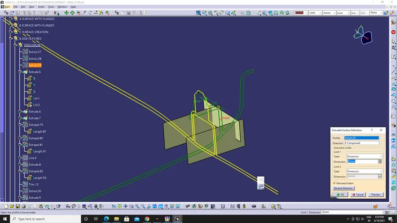
1. Extract the lines from the given master section and extrude them along X & Z direction.
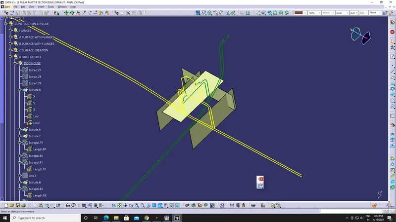
2. Extrapolate and trim the extra portion.
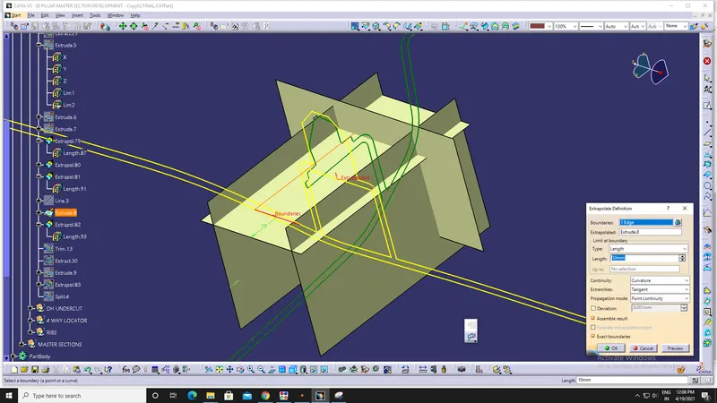
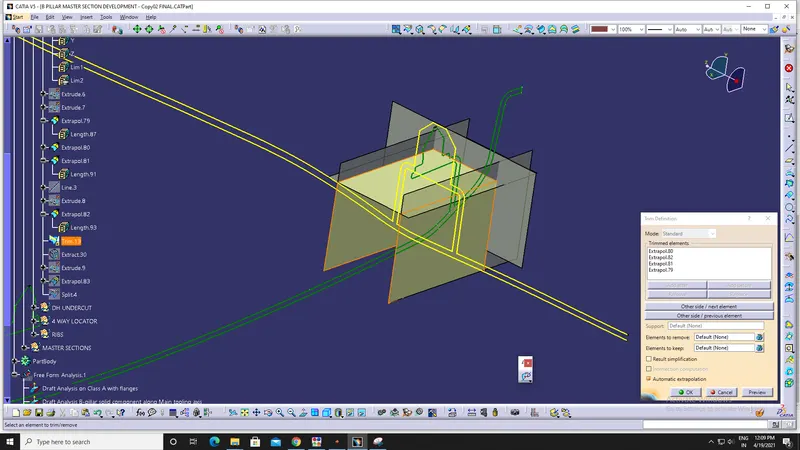
3. Extract the limit edge from the master section and split it with the doghouse surface to get the proper shape.
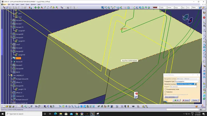
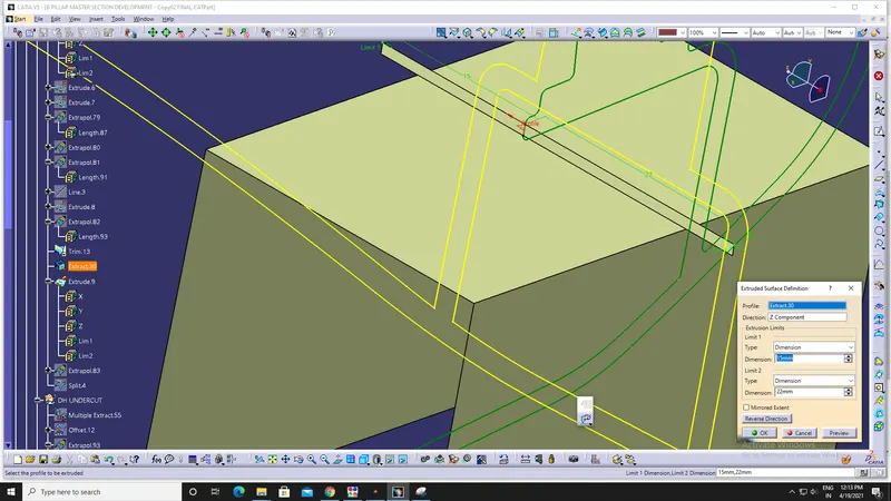
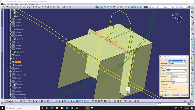
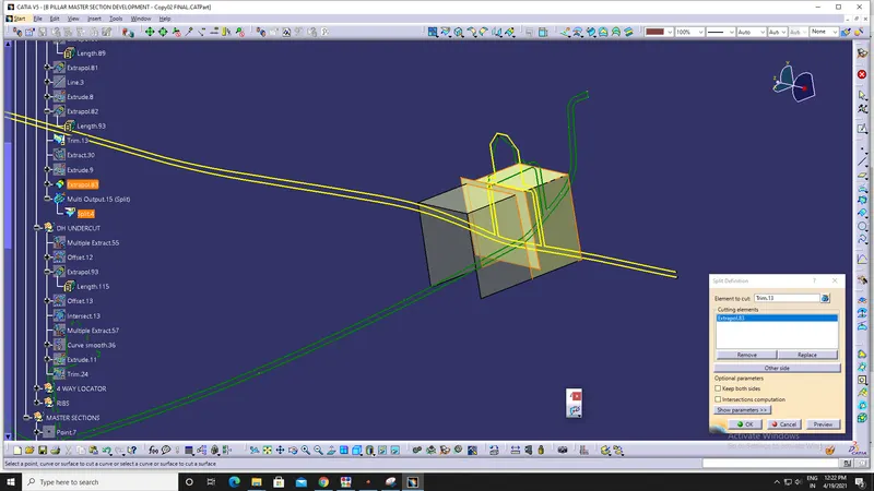
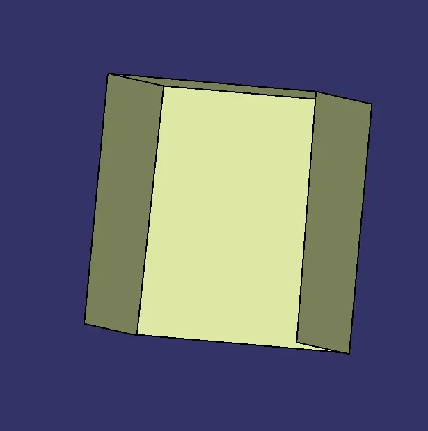
3. Insert a new body and thicken the doghouse surface created for 2mm.
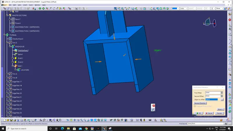
4. Now using the extract,offset, extrapolate and trim create the under cut of the doghouse.
There is an under cut at bottom of the Dog House an there are certain rules to be followed,
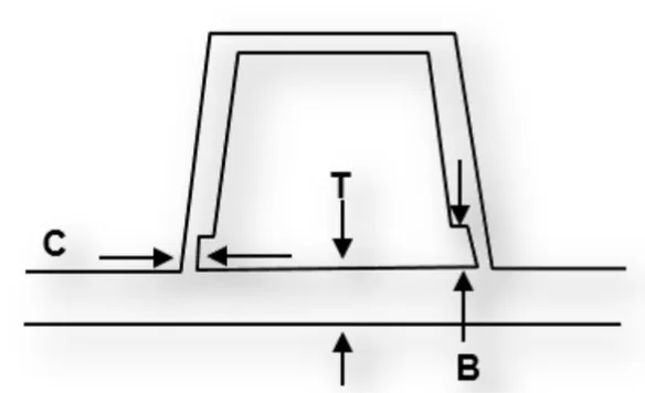
Doghouse wall thickness at the intersection of the part wall (C) should be 40% or less than the main wall thickness (T).
Height (B) should be between 3.0 – 6.0mm
Considered the following values for design:
Thickness (T) = 2mm
C = 0.4*2 = 0.8mm
B = 5.0 mm
The under-cut at the bottom of the Doghouse can be done by creating a surface of required dimensions and splitting it form the Dog house solid body.
(The surface body for under-cut can be done by just offsetting and trimming the surfaces.)
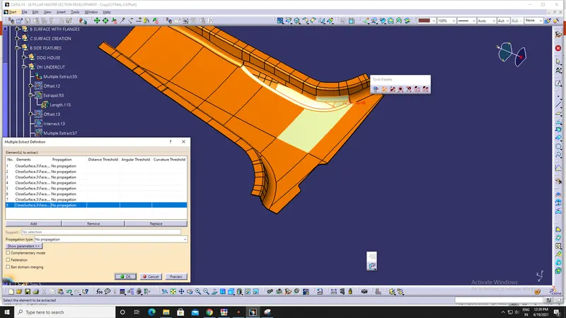
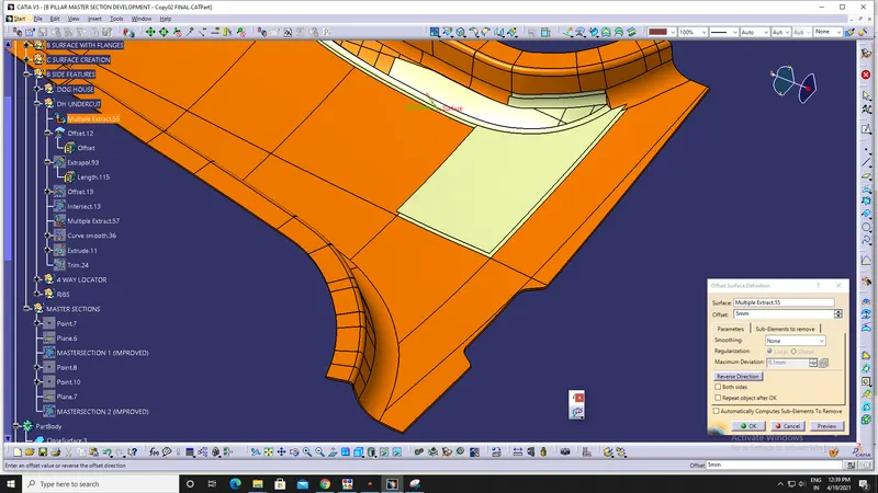
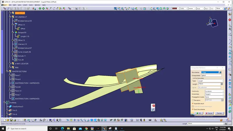
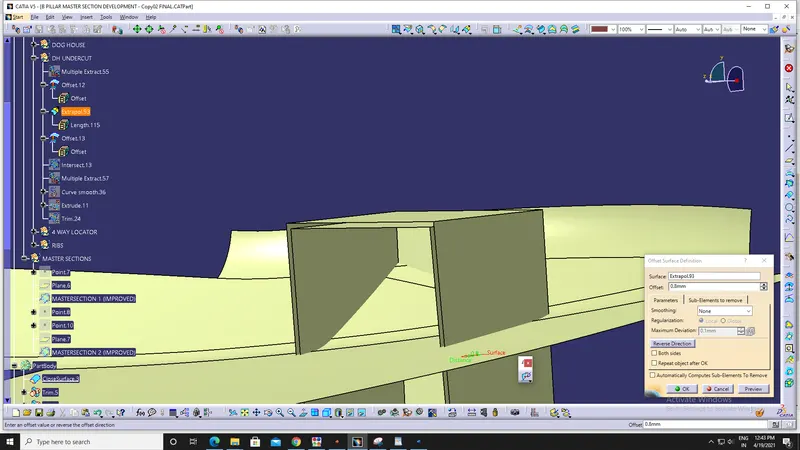
5. Create a intersection curve using doghouse surface and the base offset surface (0.8mm).
Extract that curvw, provide smooth curve, extrude and trim it.
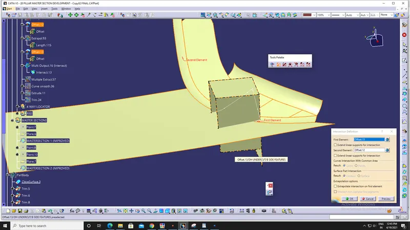
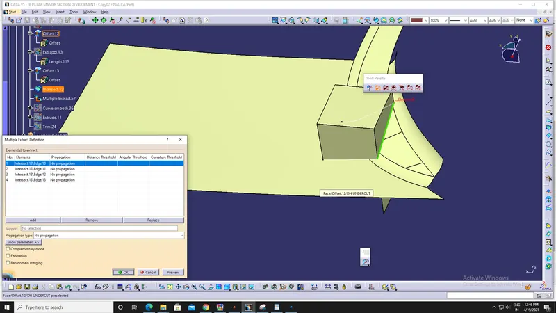
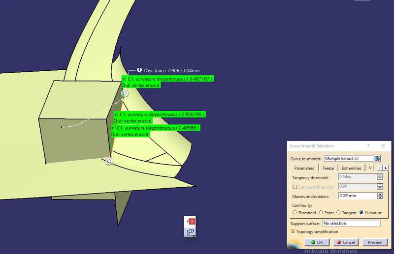
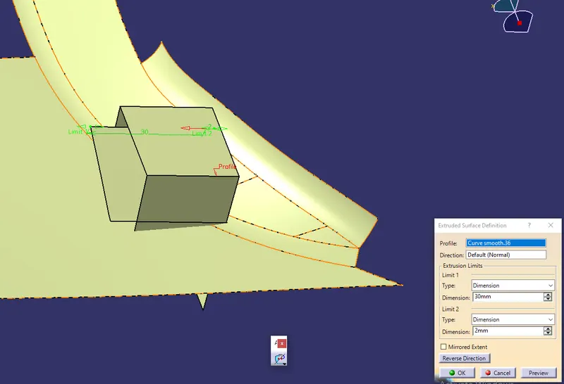
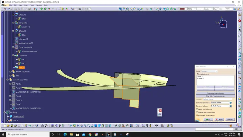
Doghouse under cut surface.
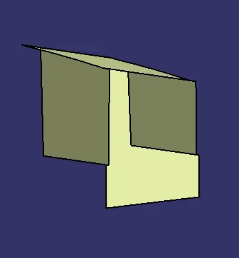
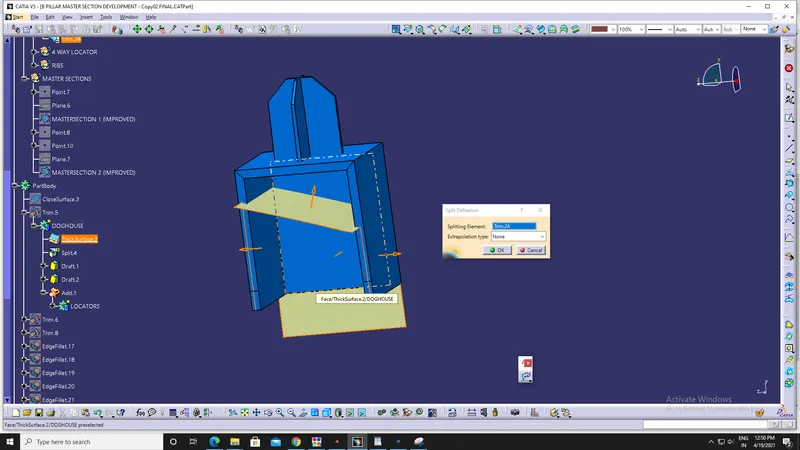
6. Now, split this surface with the doghouse solid component.
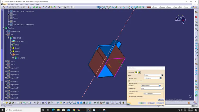
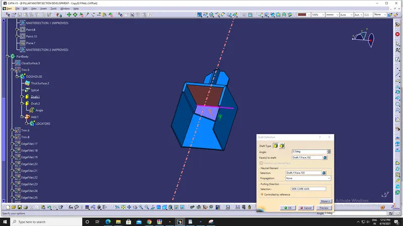
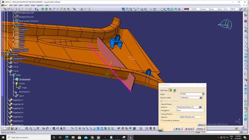
Provide draft of 0.5 degrees to the dog house along main tooling axis.
b. 4-way Locators:
These are used for placing the component in properlocation and locking the movement.
The locators are created without considering the master section (because of improper design).
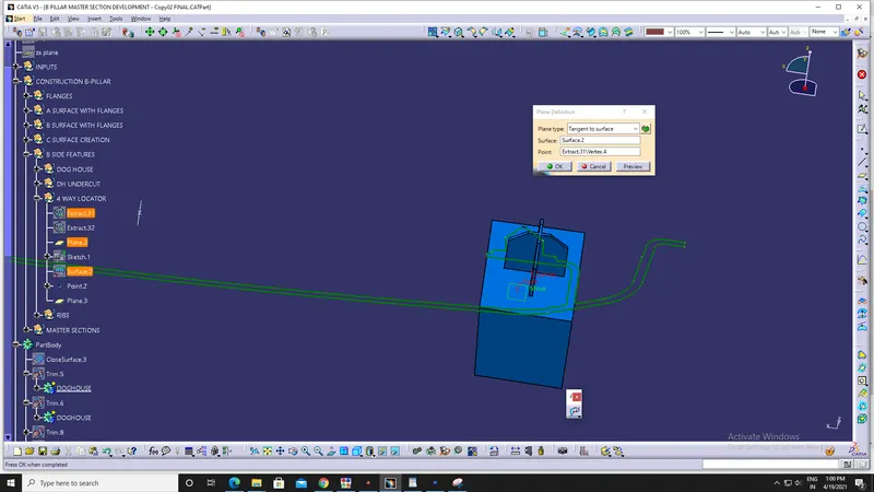
1. Create aplane on the top surface of the dog house and define a positioned sketch.
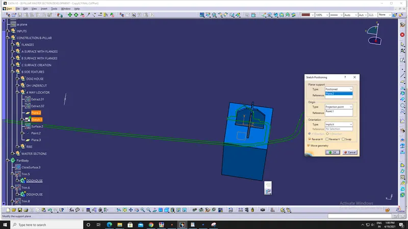
2. After defining the position sketch, draw the profile for the 4-way locator.
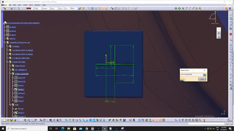
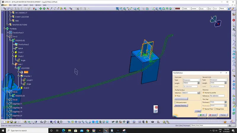
Then create a new part body and pad (thick 1mm) it to 18mm height.
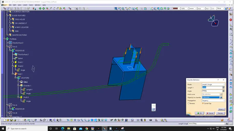
3. Provide chamfer of 5 X 45 degrees and provide draft of 0.5 degrees.
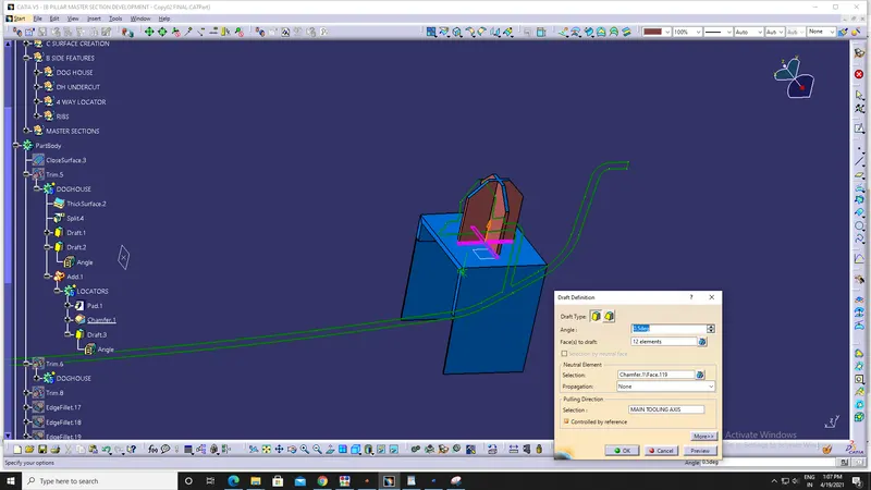
4. Now, Add 4-way locator to Doghouse.
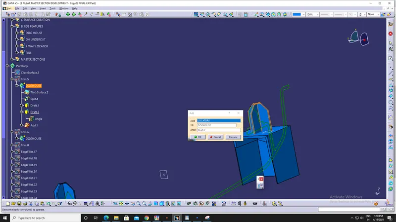
c. Adding Doghouse and Locator to part body (solid B-pillar).
1. Create a point in between the mastersection 2 and insert plane. Then paste the doghouse using paste special option and make symmetry with the plane created.
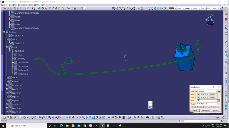
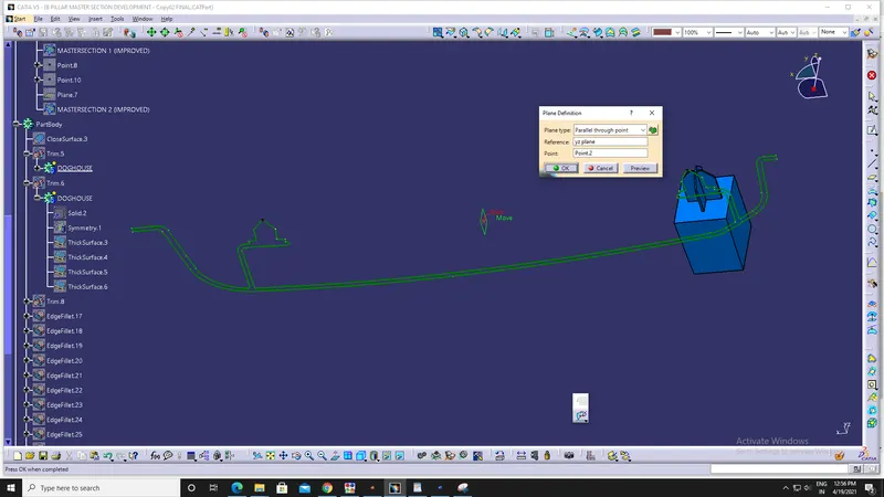
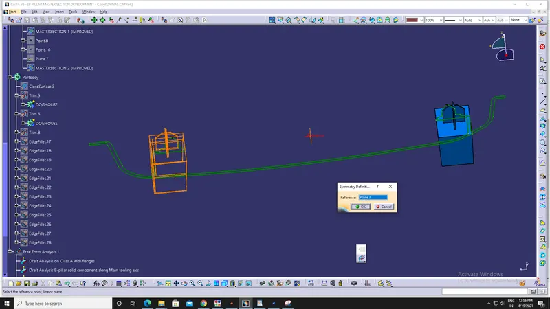

The bottom length of the other doghouse is increased so that it can union trimmed with main component.
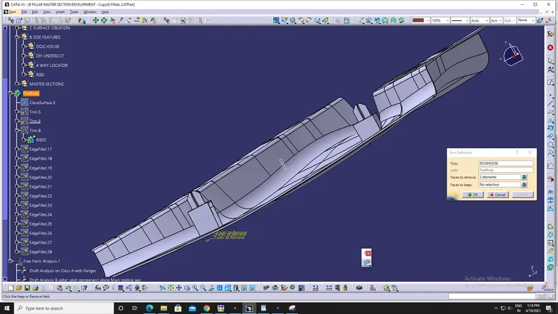
2.Now, using 'Union trim' Boolean operation trim the extra portion of the Doghouse.
Creation of Side core axis:
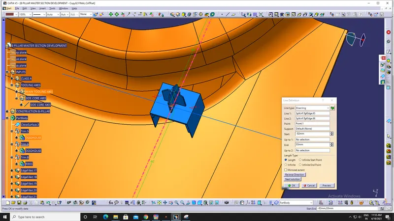
Since the inner surface of the Doghouse cannot be cleared alon main tooling axis, So side core axis is created.
Using the bisecting option in line creation the side core axis is created.
The edges (top) of the doghouse are taken as Line1 & Line2 as shown in below snap.
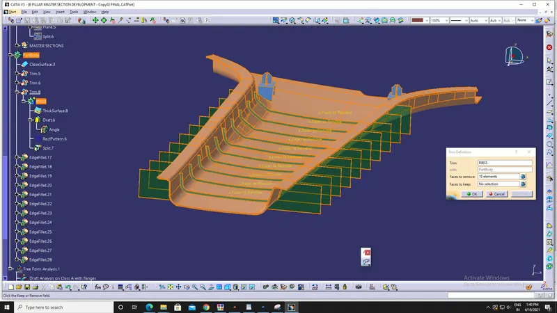
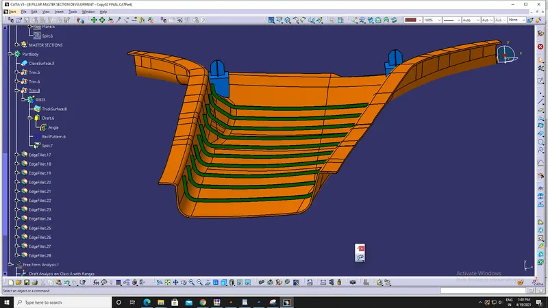
d. Ribs:
Ribs are created to provide enough strength to the component.
1. Create a plane and define position sketch.
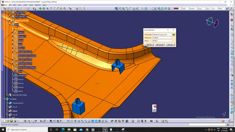
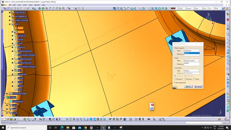
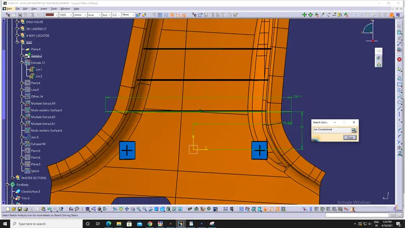
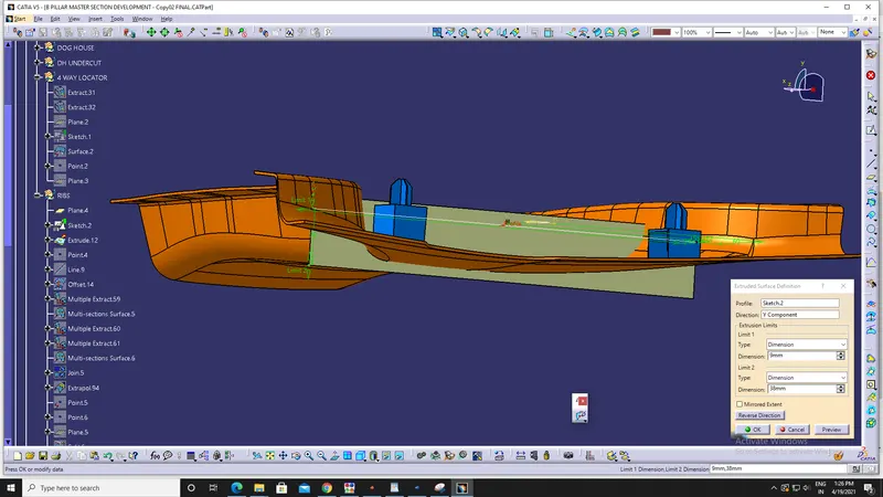
2. Draw a line and extrude it along Y-direction.
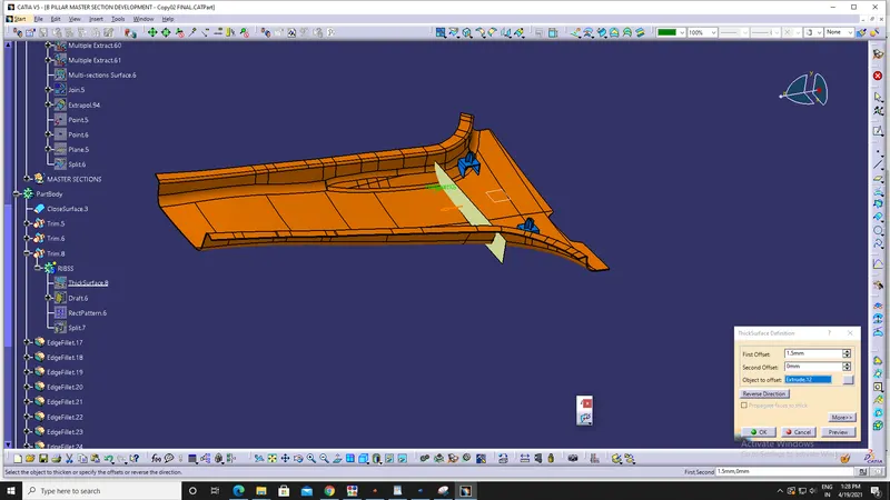
3. Using thicken option give thickness to the surface (1.5mm) and provide draft of 0.5 degrees.
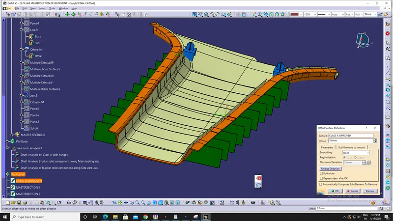
3. Offset the given class A-surface to 5.8mm and extrapolate it.
(Open patches formed during offset are solved using multisection surface option)
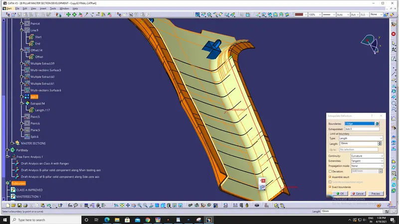
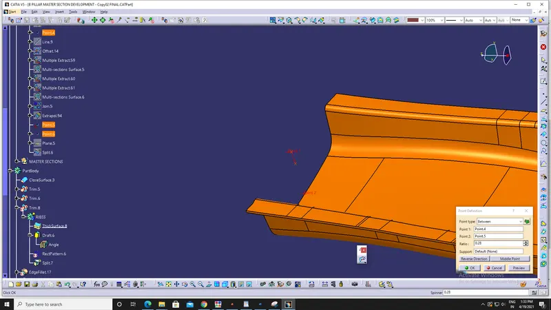
4. Now, create a line using two points in such a way that the line should be in between the B-pillar channel.
Then, using rectangular pattern create the pattern of ribs with 50mm distance between them.
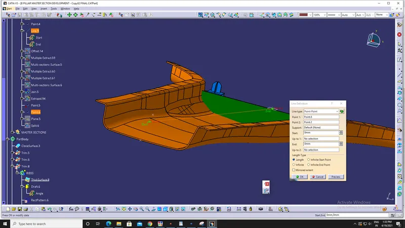
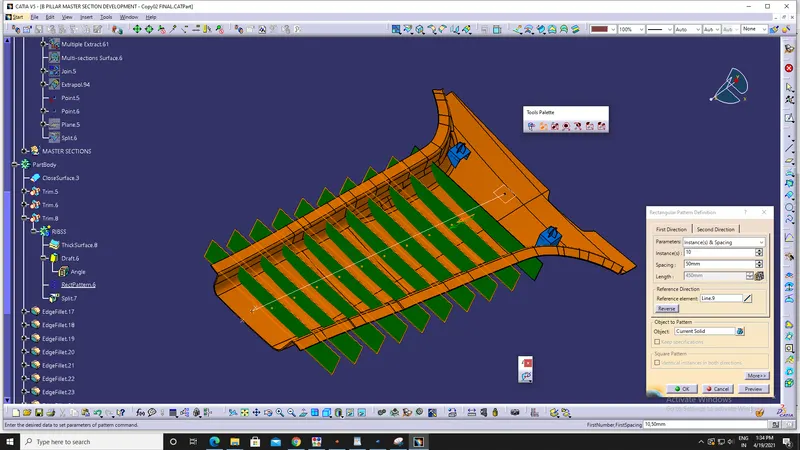
5. Split offset surface with the ribs.
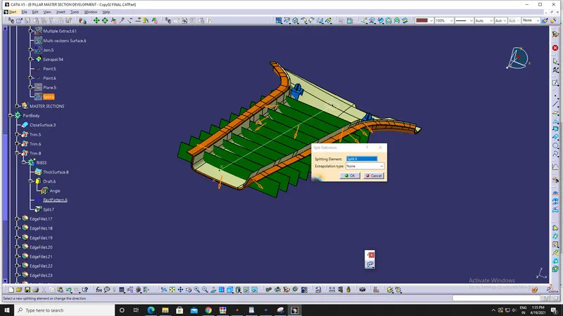
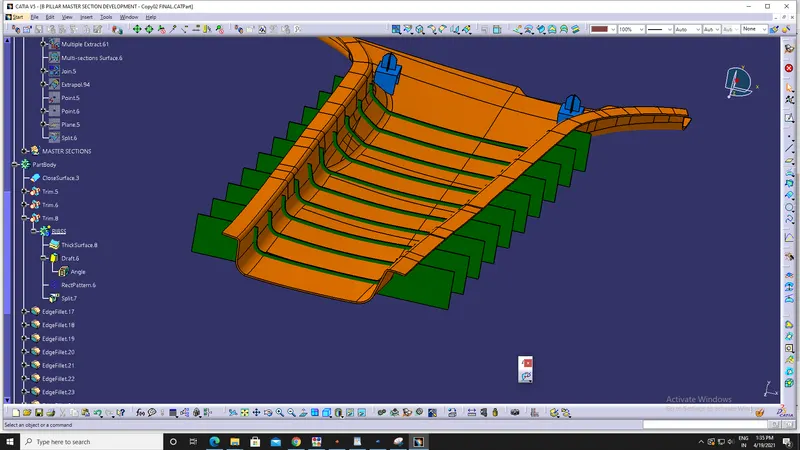
6. Union trim the ribs with the Solid B-pillar.
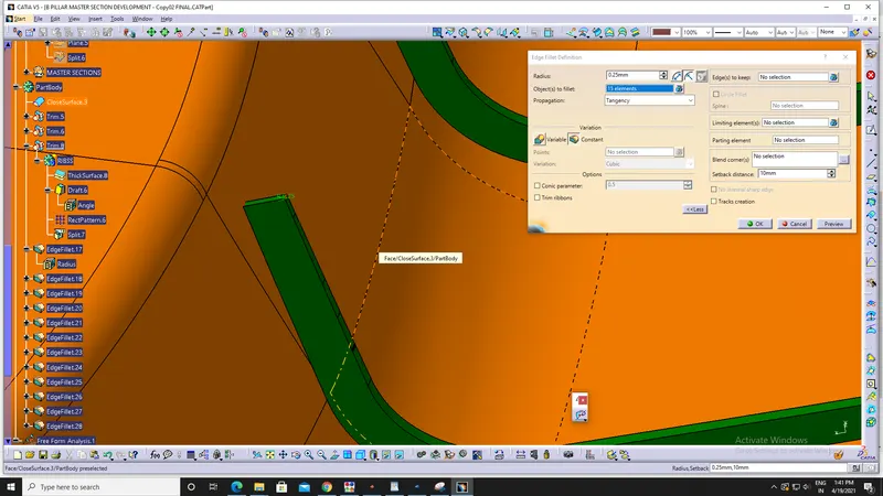
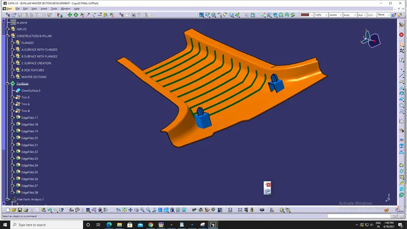
Provide fillet to the sharp edges:
Fillet of Radius 0.25mm is given to all sharp edges.
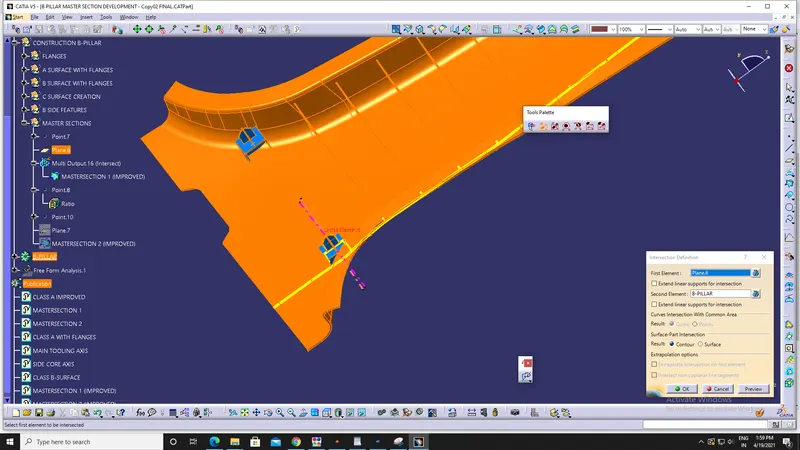
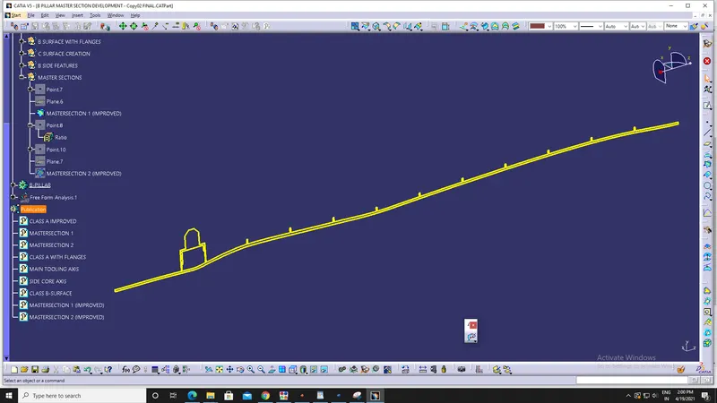
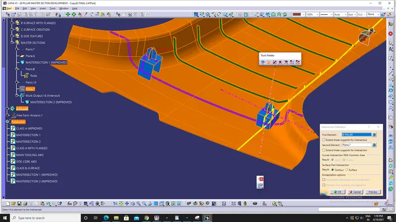
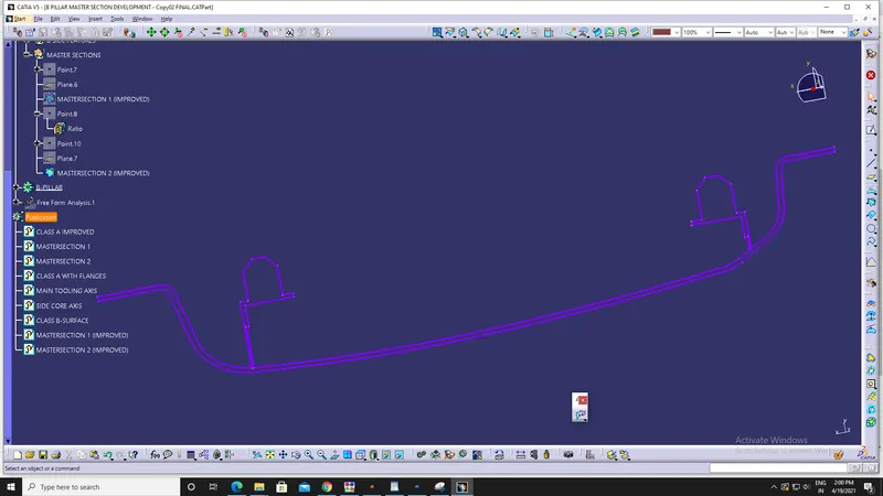
Creation of Master section:
1. Create three points and create a plane using these points.
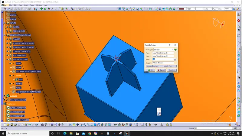
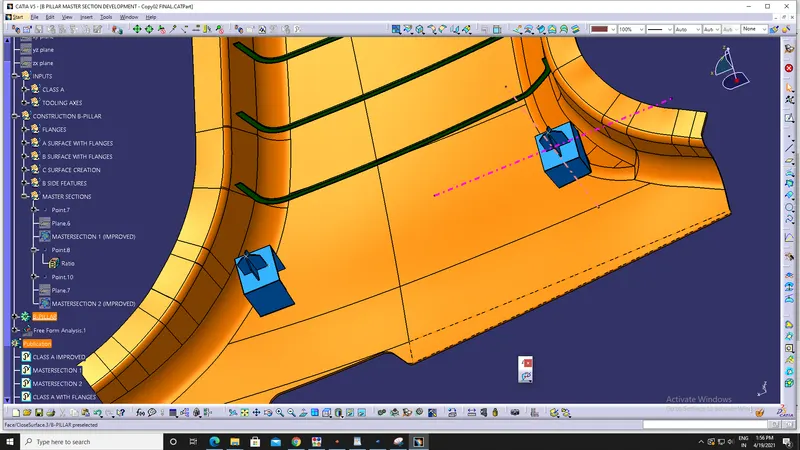
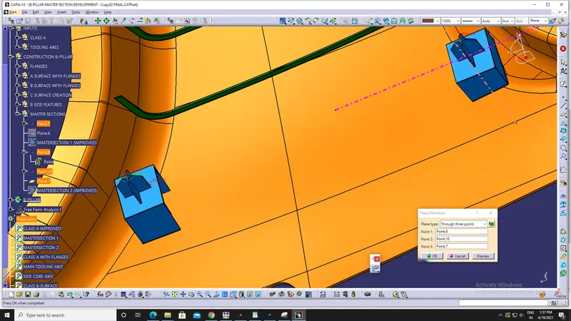
Another plane is created on the other side at cente of the locator.
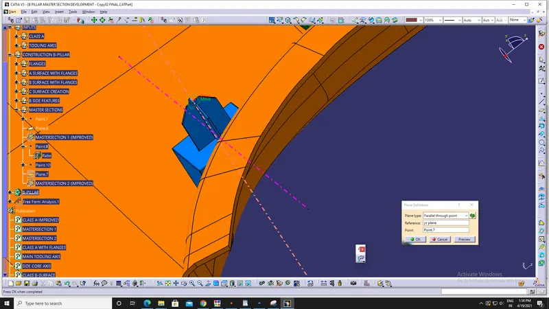
2. Now, create intersection curves using the planes and the Solid B-Pillar.
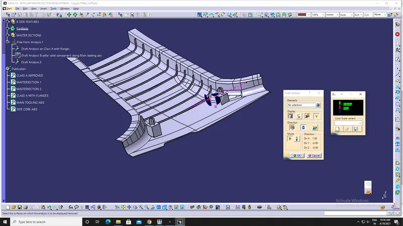
Steps involved in Draft analysis on Class A-Surface:
1. Select 'Customize view parameters' from the 'View mode' and choose 'Materials'.
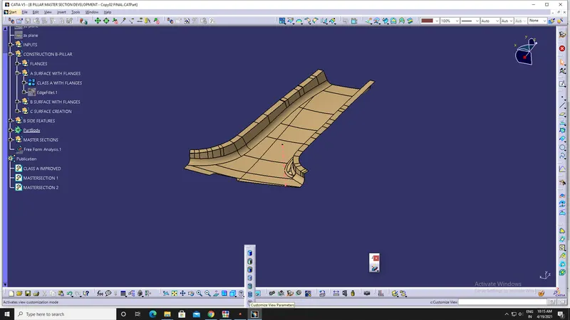
2. Select 'Feature Draft Analysis' from the 'Analysis toolbar'.
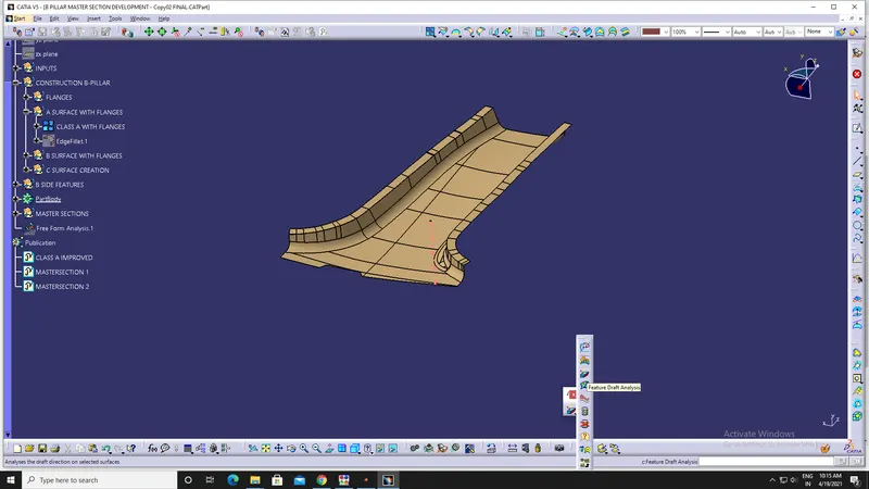
3. Now, holding the red-dot, which is on the compass (present on Top-right corner of the window) align with the Tooling axis and lock it.
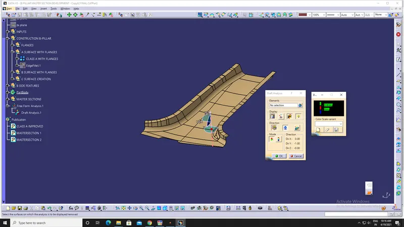
4. Set the Minimum draft angle (3 degreeS) in 'Draft Analysis' dialog box (Which has different colour bars).
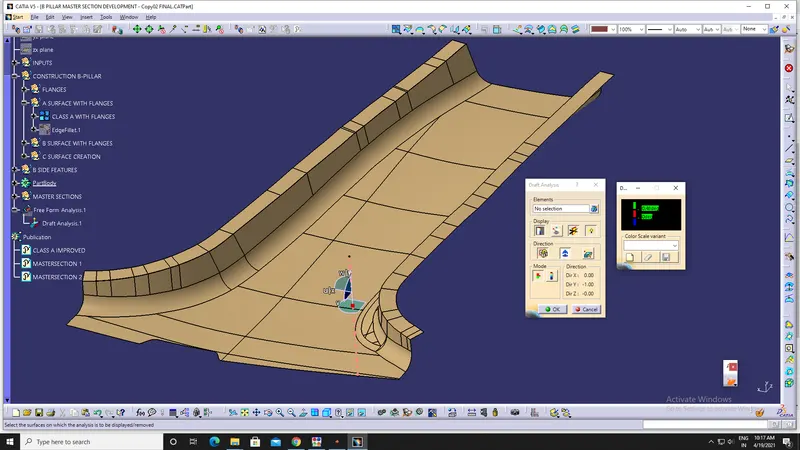
5. Choose Solid component as element in 'Draft Analysis' dialog box or Just click on the surface.
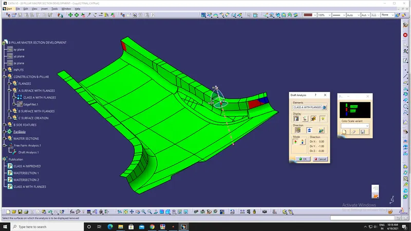
After selecting if the surface's colour changes to,
Green, then the draft of that surface has minimum draft angle of 3 degree.
Red, then the draft angle of that surface lies between 0-3 degree.
Blue, then the draft angle of that surface is less than 0 degree.
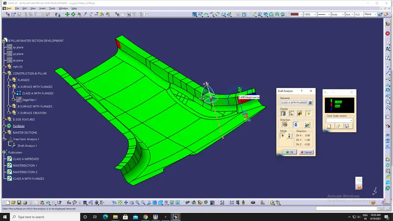
6. By choosing 'Analyse under running point' from 'Analysis toolbar' we can check the draft angle at any point on the surface just by moving the pin.
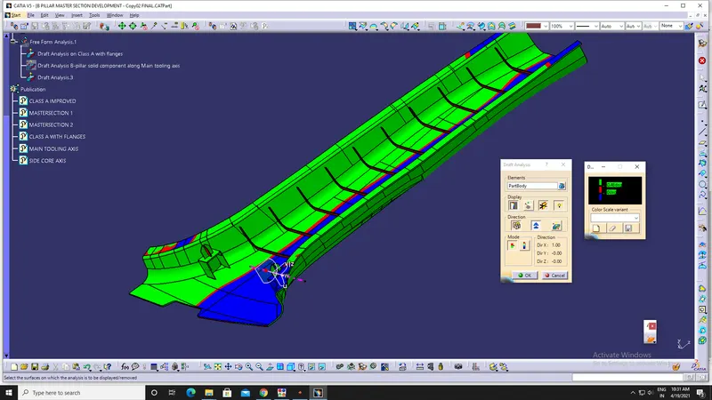
Steps involved in Draft analysis on Solid component:
a. Along Main tooling axis:
Same steps should be followed as above, only change is the minimum draft angle will be 0.5 degrees (because of B-side features).
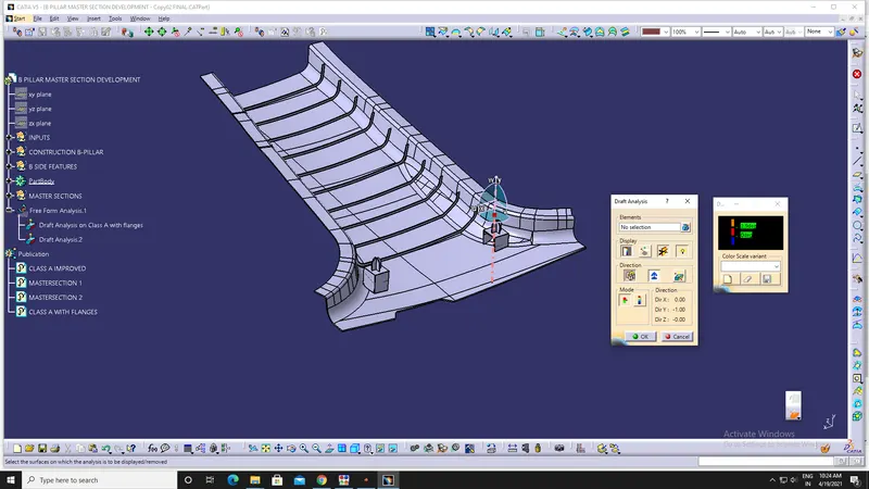
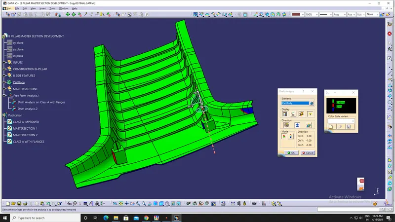
If the colour of the surface is,
Green, then the draft of that surface has minimum draft angle of 0.5 degrees.
Red, then the draft angle of that surface lies between 0-5 degrees.
Blue, then the draft angle of that surface is less than 0 degrees.
Along the main tooling axis the A, B-side surface, Locators, Outer surface of the Doghouse & Ribbs are cleared. To clear the inner surface of the Doghouse side core axis is required.
b. Along side core axis:
Same steps should be followed as above, only changes are the minimum draft angle will be 0.5 degrees (because of B-side features) & the tooling axis will be the side core axis.
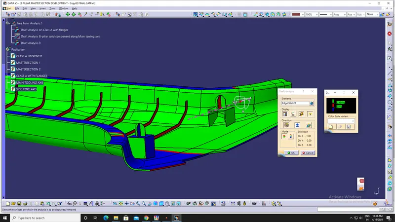
If the colour of the surface is,
Green, then the draft of that surface has minimum draft angle of 0.5 degrees.
Red, then the draft angle of that surface lies between 0-5 degrees.
Blue, then the draft angle of that surface is less than 0 degrees.
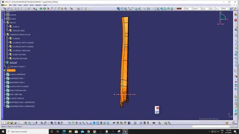
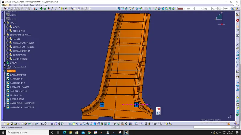
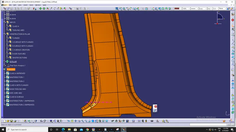
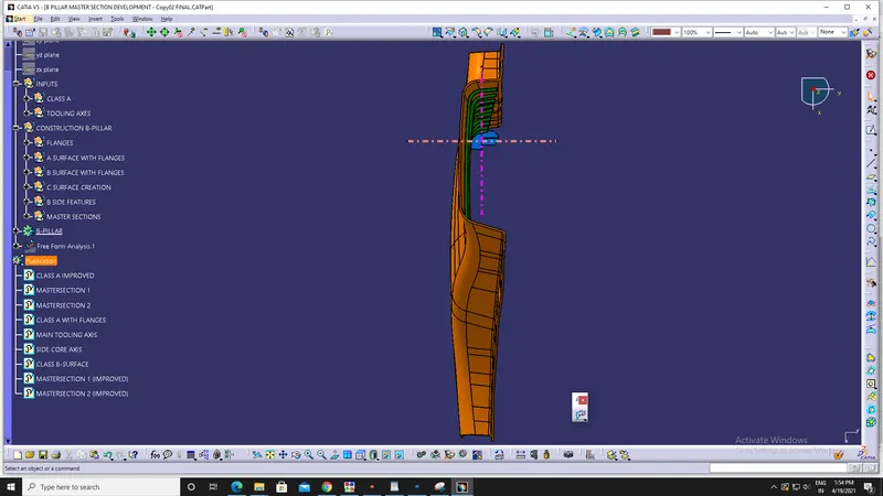
Screenshots of the B-Pillar in different orientation:
1. Isometric View:
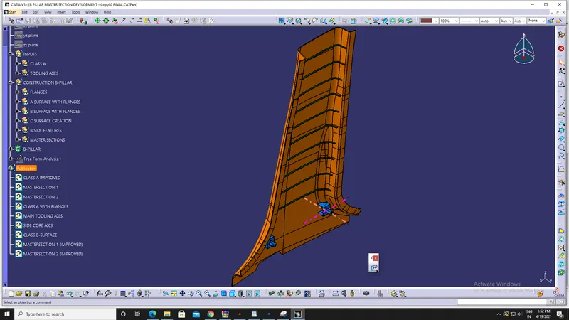
2. Front View:
3. Rght side View:
4. Left side View:
5. Top View:
Conclusion:
B-Pillar is created and draft analysis is performed on both A-Surface and Final componet.
The detailed report for the draft analysis is given in the PPT file, which is attached with the CAT file and uploaded.