Week 9 - Project - Master Section Development
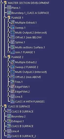
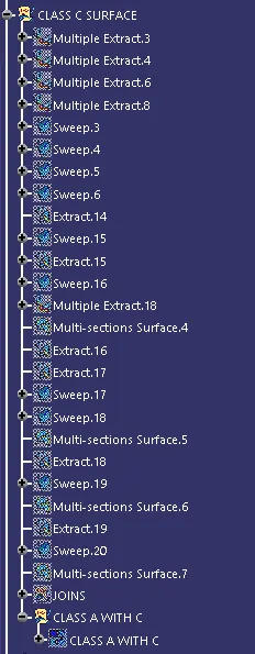
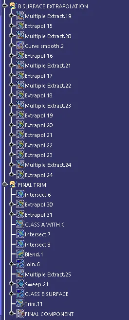
TREE STRUCTURE OF B-PILLAR
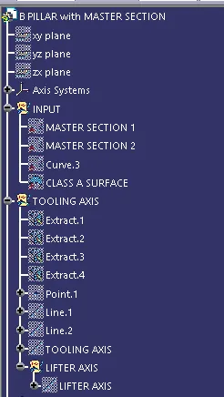
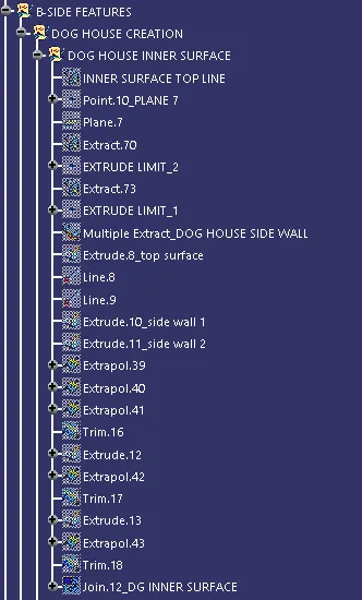
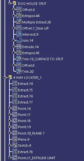
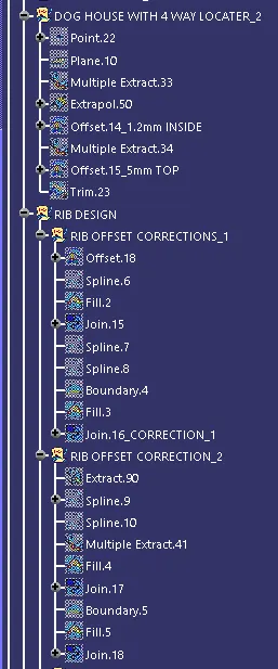
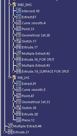
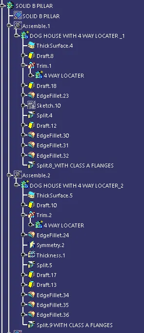
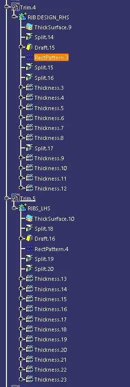
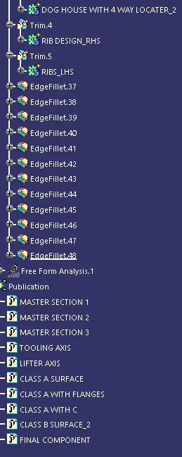
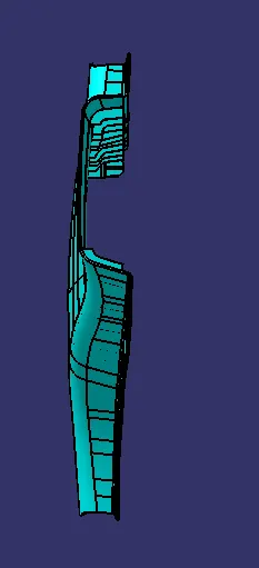
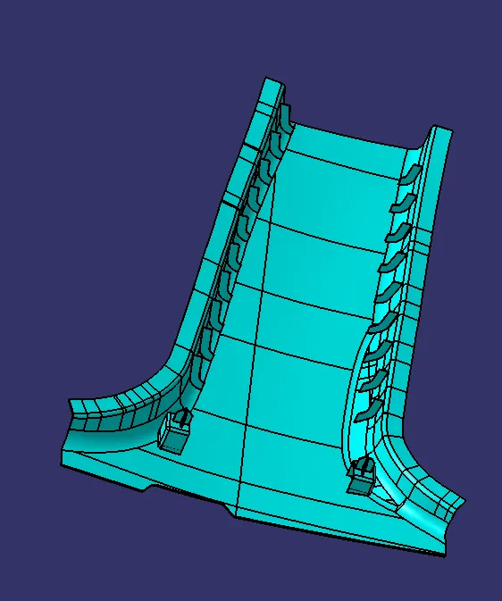
FINAL COMPONENT WITH ENGINEERING FEATURES VIEWS
FRONT
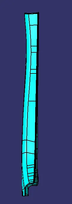
SIDE
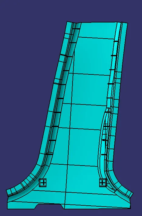
TOP
ISO
CREATION OF CLASS B AND C SURFACE
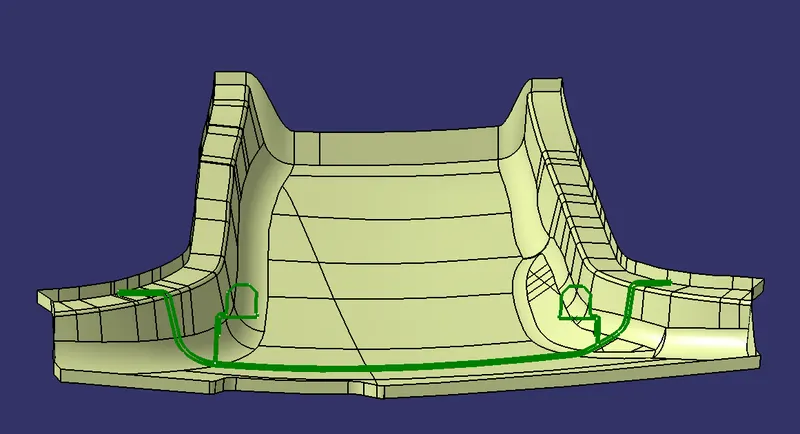
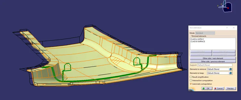
At first, flange at both ends is created using Joint operation with Class A surface keeping the master section as reference and trimmed with Class A as shown below.
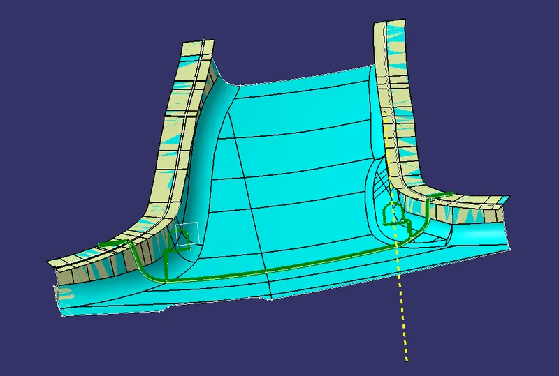
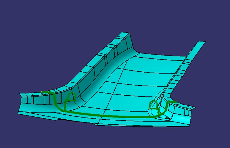
The Class A surface with Flange is offsetted for 2mm generating B-surface which is Green in colour.
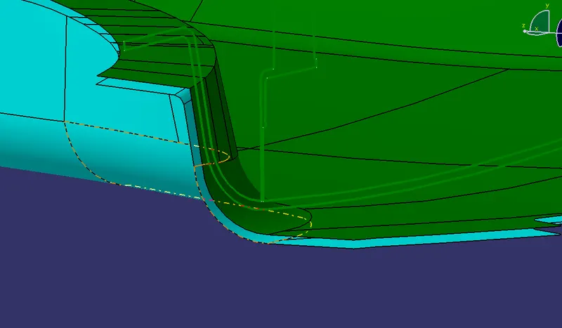
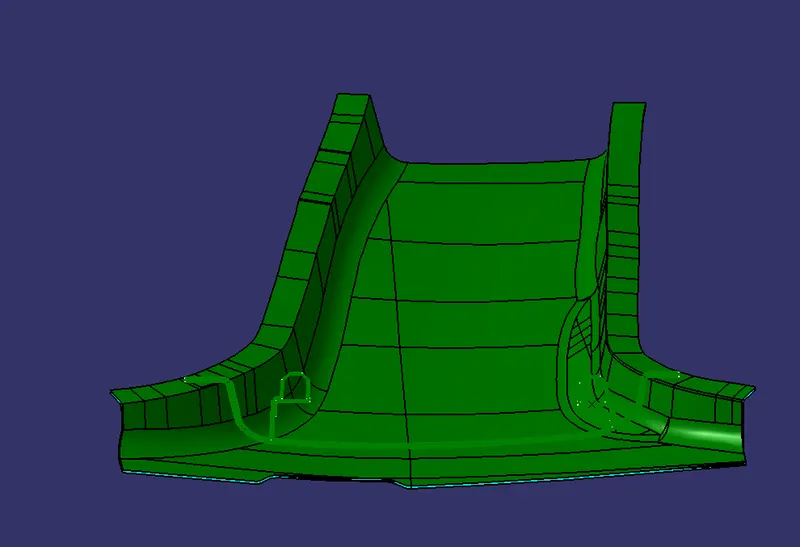
Class C surface is created using Sweep, Multi-section and Blend operation. Finally the C surface trimmed with offsetted Class B.
GENERATION OF TOOLING AXIS
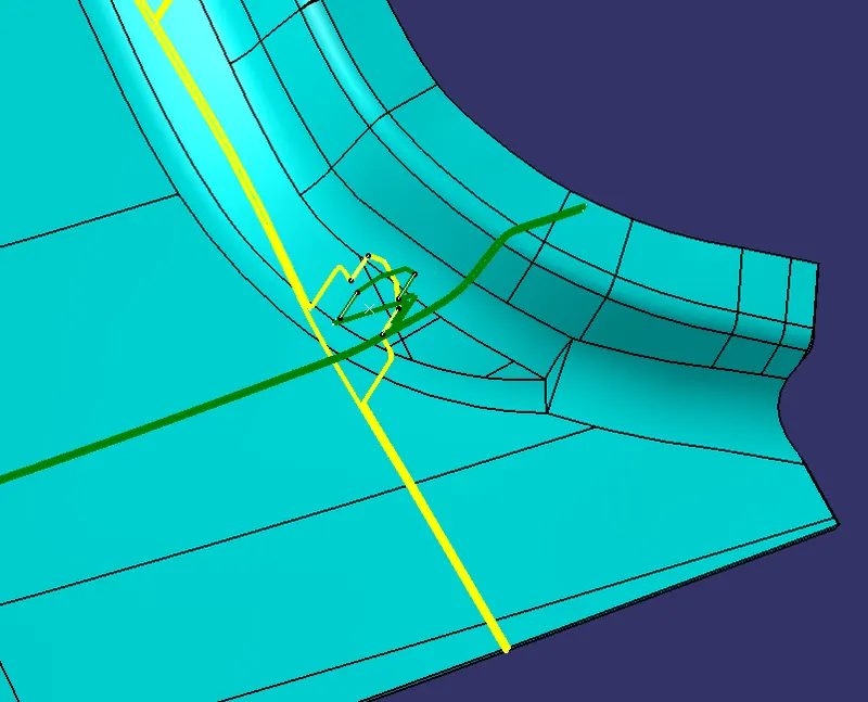
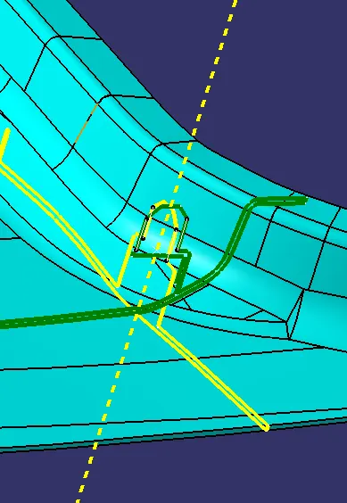
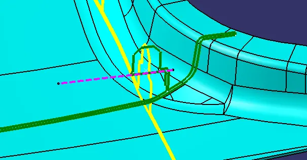
A Point has been created in the middle by extracting lines from both the master sections and a Line 1 is generated throught the point generated by using Between option in Line definition Tool. Similarly Line 2 is generated from other extracts from master section.
Now Biseting method is used to generate Main Tooling Axis by Bisecting both Line 1 and Line 2.
The same Point 1 is used to generate another Tooling Axis to clear the inner surface of Dog House.
***We can find the draft analysis of both the Tooling and Lifter Axis at the bottom of the report.***
CREATION OF ENGINEERING FEATURES
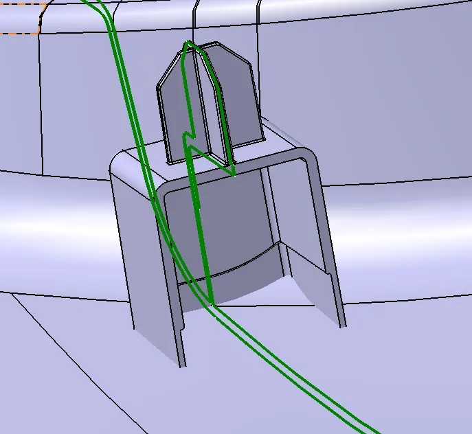
CREATION OF DOG HOUSE WITH 4-WAY LOCATER-1 and 2
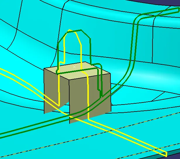
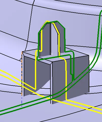
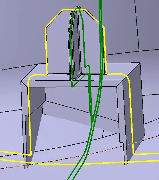
A Dog House [DH] at RHS is created using surface extrude from extracts obtained from the master sections. A dog house extrude is thickened 2mm using Thick surface tool available in Part Workbench.
A split is done for the contact surface of the Dog House with Final component.As per design standards it should be 40% of the wall thickness [i.e 0.8mm].
A 4-Way Locater is generated as per the design standards using extrude from the extracts obtained from the master sections as shown below.
This Dog House at RHS was translated to LHS using Translation option available in Part Workbench as shown below.
**A min draft of 0.5 deg is given to the outer as well as inner surface of the dog house, Locater and Ribs in the direction of respective Tooling direction.
CREATION OF LHS and RHS RIBS
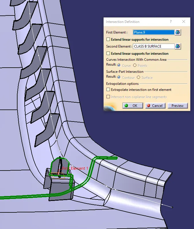
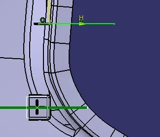
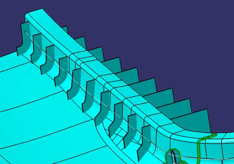
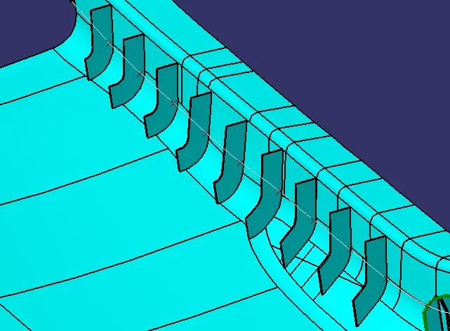
An intersection is made between the XZ plane and the Final Component. A Curve obtained as shown below. A point is made along the curve 50mm apart. On the point, a line is generated using Line option available in Sketcher Workbench.
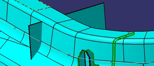
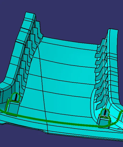
An Extract is made from the line and thickness of 0.8mm is given using thickness option available in Part Workbench. A draft of 0.5 deg is given to the solid rib. A rectangular pattern made as shown below and the resulting pattern gets splited with the offseted B-surface [offset = 10mm] and the resulting part gets Boolean[Union Trim] with the Solid B-pillar to get the Ribs that we see in the below image.
This same approach was used for generating Ribs at LHS.
DRAFT ANALYSIS
DRAFT: When the molten plastic is completely ejected into the molded cavity and it is allowed to cool it tends to shrink to the core side of the mould and thus there deveolps a friction between the part [final output] and the mould. To overcome this drafting is required. It is required on all parts in the direction of mold movement in order to allow parts to release or eject from the mold properly
Drafting Analysis is used to generate computational analysis of the component clearing the mould cavity without any damage [by friction] between the final component. It checks whether the Main Tooling Axis is correct or not thereby analysing the draft of the component. It shows whether all faces of the component has the required draft or not using value assigned colour codes . It further helps us to detect corrections in the earlier stage [i.e design] thereby preventing the cost and damage to the component.
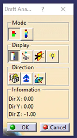
At First, Compass Tool  is used to position the co-ordinate plane into the main tooling axis of the component and locked using Lock Tool
  .
.
This compass tool is available in the drafting Dialogue Box along with Lock and Analysis under Running point Tool  in the display section of the dialogue box.
DRAFT ANALYSIS OF CLASS A SURFACE
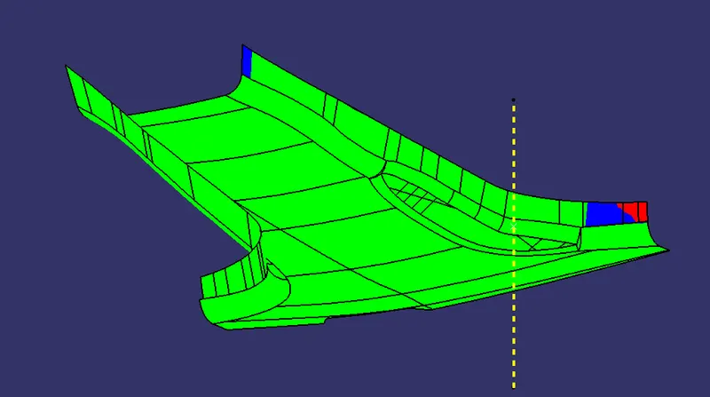
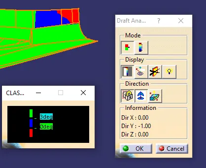
The above image shows the draft analysis of Class A surface and colour code identification.
OBSERVATION:
The region in Red has the value ranging from -1.00 to -1.9 deg.
The region in Blue has the value ranging from 0.8 to 2.9 deg.
Most of the surface of Class A is Green in colour indicating the faces cleared the draft requirement of min 3 deg. But still we can see Red and Blue colour in the surfaces of Class A. Adjusting the Tooling Axis w.r.t the surface in conflict [red, blue] would give us the required tooling direction.
DRAFT ANALYSIS OF FINAL COMPONENT WITH ENGINEERING FEATURES
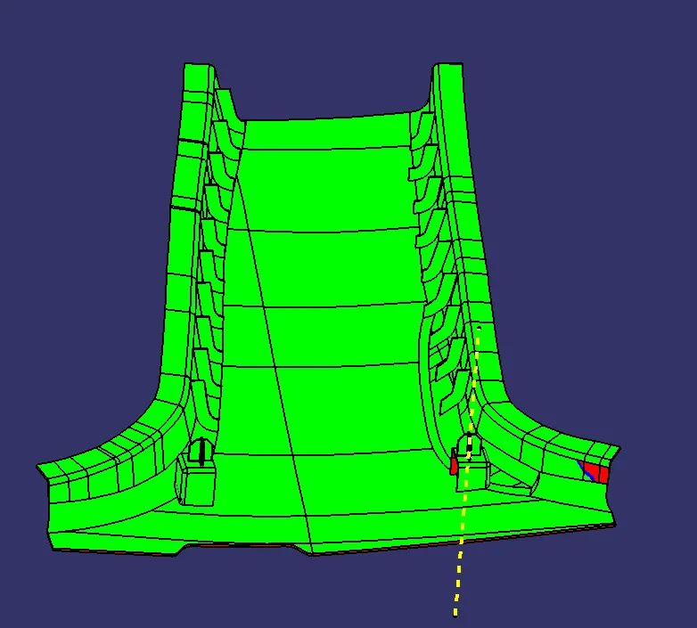
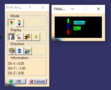
The above image shows the draft analysis of Final output including B-side Engineering Features surface and colour code identification.
Here the outer surface of B-side features such as Ribs, Dog House and Locaters are getting cleared which are indicated in Green colour.
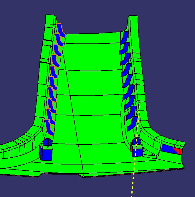
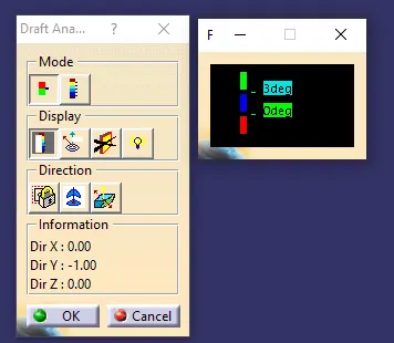
Here, the Draft Analysis is made by giving the min draft as 3deg and the analysis is shown above with its corresponding colour code identification.
OBSERVATION:
The region in Red has the value ranging from -0.3 to - 1.5 deg.
The region in Blue has the value ranging from 0.05 to 0.3 deg.
Most of the surface of Class A is Green in colour indicating the faces cleared the draft requirement of min 3 deg. But still we can see Red and Blue colour in the surfaces of Class A. Adjusting the Tooling Axis w.r.t the surface in conflict [red, blue] would give us the required tooling direction.
DRAFT ANALYSIS OF DOG HOUSE USING LIFTER AXIS
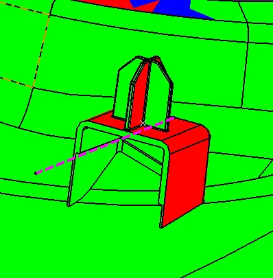

The above image shows the draft analysis of Dog House Inner surface and respective colour code identification.
From the above image it is understood that the inner surfaces of the dog house clears the min draft requirement of 0.48 deg.