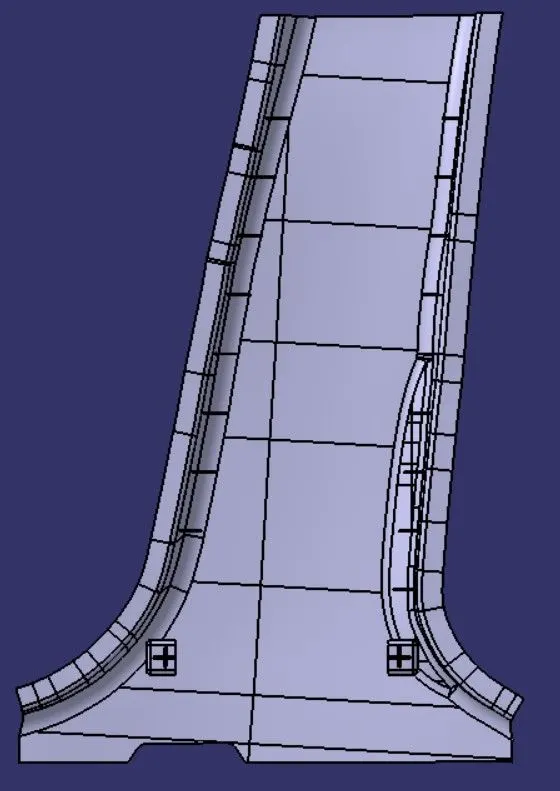
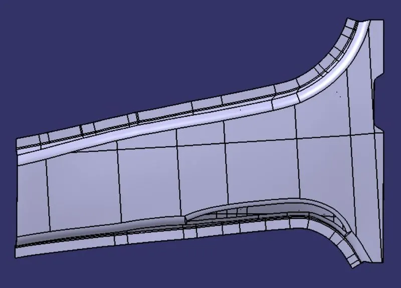
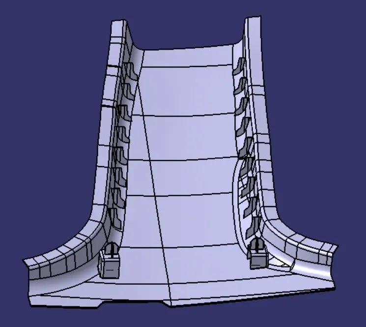
Week 9 - Project - Master Section Development
MASTER SECTION DEVELOPMENT
JEEVA R
AIM:
To create B pillar from provided master section.
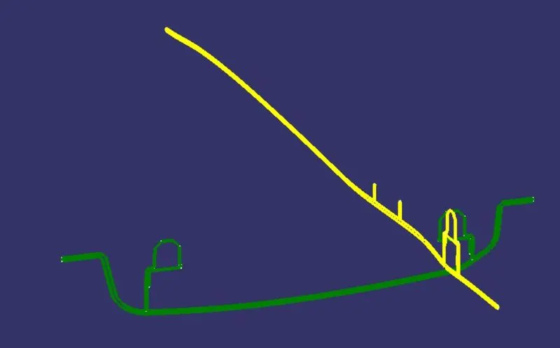
OBJECTIVE:
Creating the B-Pillar Master Section development through the given Class-A surface. To begin with, the tooling axis for the given Class-A Surface is created to meet the requirements of the draft angle and at the end perform the Draft analysis on the model.
Creating the Dog Houses, Ribs, and the locators considering the design rules
The Thickness of the component is obtained from the Master section
INTRODUCTION:
Draft:
- A draft angle is a slant that is applied to each side of most features of an injection molded part. In other words, Draft is providing tapers on the product features such as walls ribs posts and bosses that lie parallel to the direction of the release from the mold part ejection.
- The nominal draft is 3mm for plastic components and for automotive sheet metal components is 7mm
Tooling axis:
- It is defined as the direction in which the molds opens or core and cavity, with the help of tooling axis created along X and Y axes are used for creating the Main Tooling axis by considering the B side features which usually cleared in main tooling. Therefore, master section of locator is extracted and tooling axis is created by bisection method.
Master Section:
- The master section helps us to decide the feasibility clearance, the packaging and the fixation strategy of a component before working in 3D. on the other hand master section gives us the thickness of the component.
DOG HOUSES:
- Helps to avoid sink marks
- solves the length issues (ex: screw bosses can be formed at 100mm form B-surface)
- always design houses perpendicular to the tooling.
DOG HOUSE DESIGN CONSIDERATIONS:
- "C" is where the doghouse contacts the backside of the surface
- Doghouse wall thickness at the intersection of the part wall (C) should be 40% or less than the main wall stock (T).
- Height of (B) should be between 3 – 6 mm.
RIBS:
- Ribs are a feature in plastic injection molded parts. They are thin extensions that run perpendicular to a wall or plane. They are commonly used to provide additional support and strength to a part.
- These provide economical stiffness and strength in the molded parts without increasing the overall wall thickness.
- Facilitate locating and arresting of components of an assembly.
- Provide alignment in mating parts.
RIB DESIGN CONSIDERATIONS/RULES:
Thickness
Height
Location
Quantity
Manufacturability
- Thick ribs often cause sink marks and in turn create cosmetic problems on the opposite surface of the wall to which they are attached.
- highly glossy, critical surfaces require thinner ribs.
- if the wall thickness is less than 1mm the rib thickness should be equal to the wall thickness.
- very thin ribs can be difficult to fill.
- Measure the base thickness of the rib at the tangent of radius if radii are molded in
- The larger the area of the base of the rib the more retained heat which results in sink formation.
PROCEDURE
Connectivity of Class A surface:
The first and foremost thing to do is to check for the connectivity of the surfaces this is to ensure that there are no gaps between the surfaces if gaps are present then it should be resolved.
This can be done visually or by creating boundaries, if their gaps are present, they are graphically represented by green lines. If not while performing boundary command it shows an error.
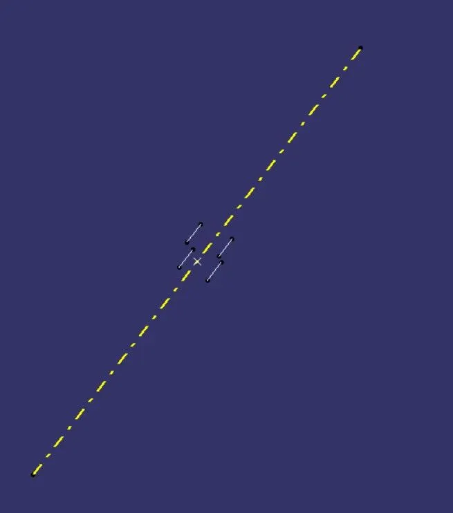
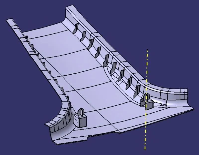
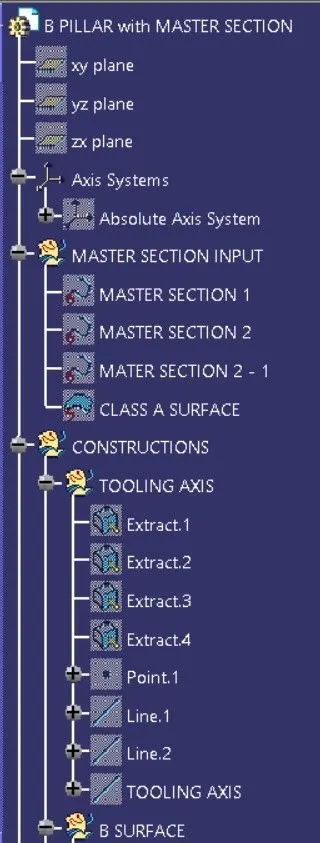
Creation of Tooling Axis for Class A surface:
Taking B side feature of master section as reference (B side features are cleared in main tooling). Tooling axis is created from provided master section.
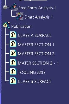
Publication:
The publication is used for easy access to published components. These will come in handy while modeling (we are not required to search the entire tree structure for a particular operation)
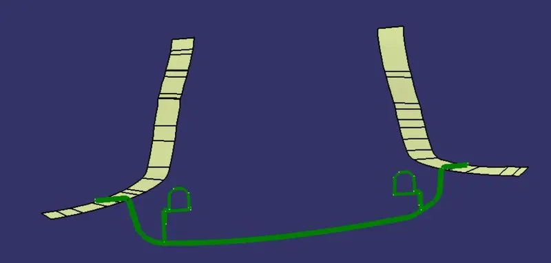
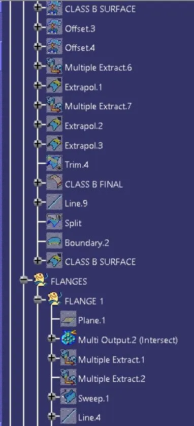
FLANGE CREATION ACCORDING TO THE MASTER SECTIONS TO CLASS A:
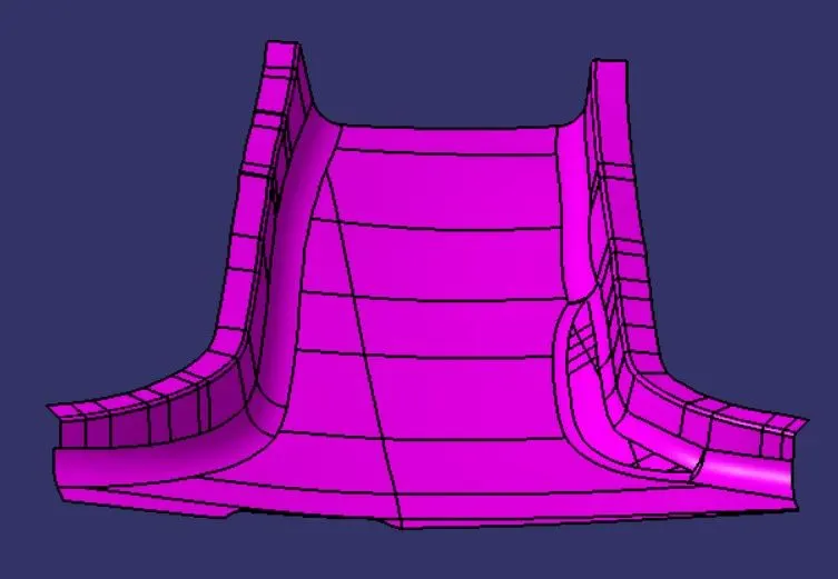
Considering the master sections provided the flange dimensions are taken later class A is modified i.e., Modified class A with flanges (Master section)
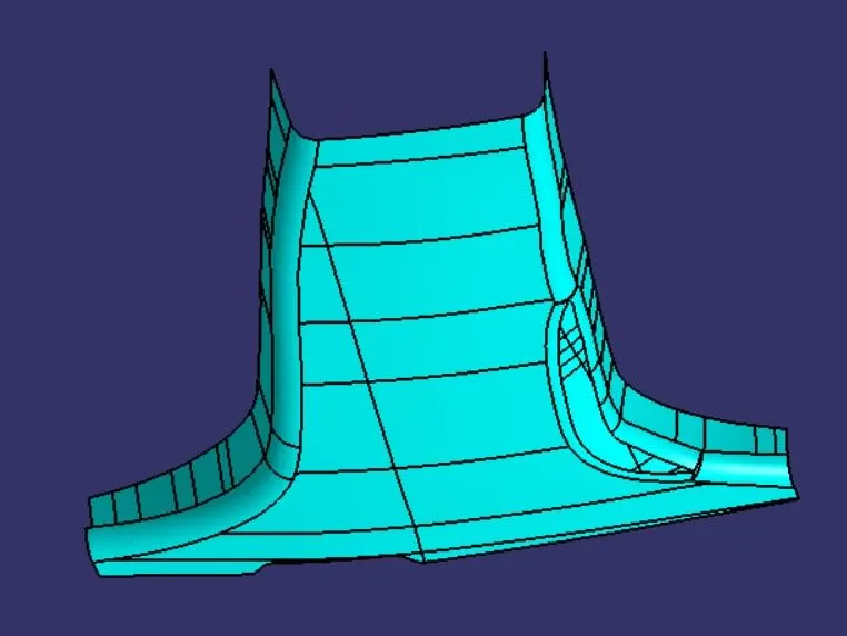
The final class A is obtained by trimming created flanges with provided class A and master sections.
DEVELOPMENT OF CLASS B SURFACE:
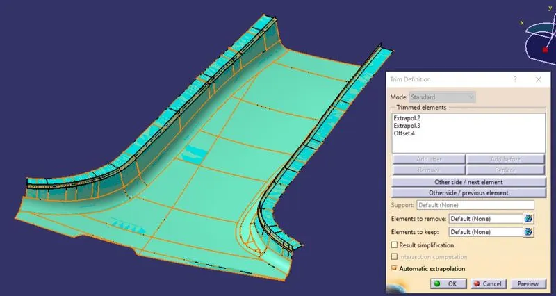
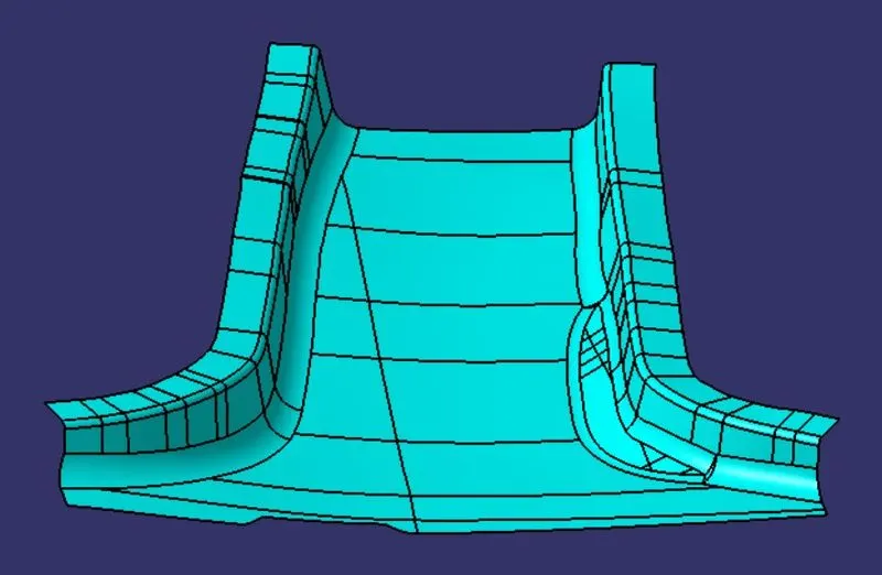
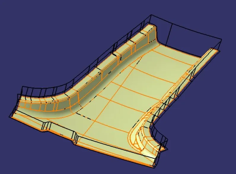
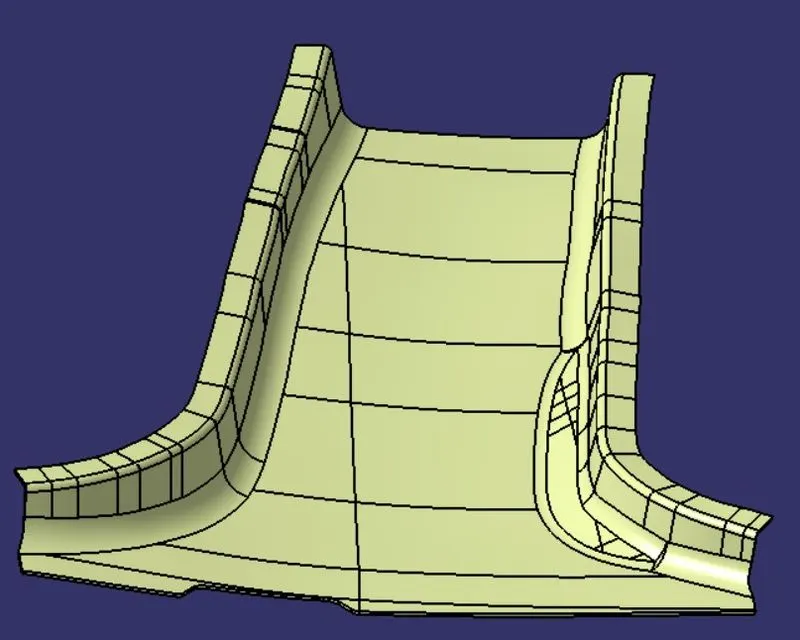
Class B surface is created by extracting each wall and untrimmed walls extrapolating the walls and then trimming the extra surfaces and offsetting it to a certain value based upon the thickness of the component where it is 2 mm as obtained from the master section. The offset surface will be the B - Surface.
DEVELOPMENT OF CLASS C SURFACE:
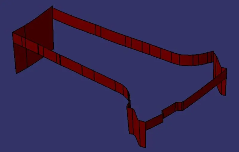
This surface is obtained by sweeping the boundaries of the Class A surface along the Tooling Axis direction, it connects A and B surfaces
Using A+C surfaces and trimming with B - surfaces, we get a closed surface.
The final trim part is converted into a solid component using closed surface command.
DOG HOUSE, LOCATOR AND RIB CREATION:
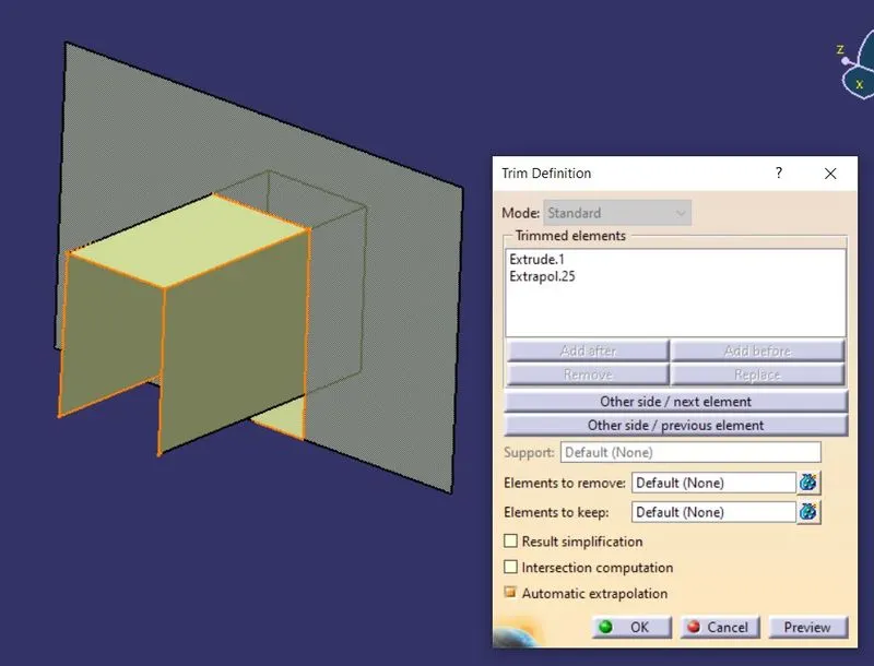
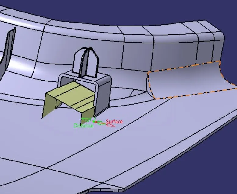
By following the master section, the doghouse, locators, and ribs are designed according to the design rules for the particular Engineering Features
For the Doghouse the lifter axis is created.
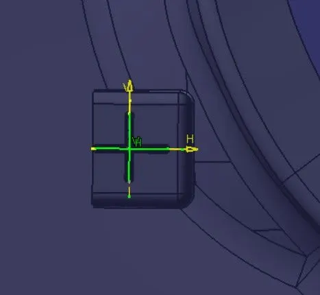
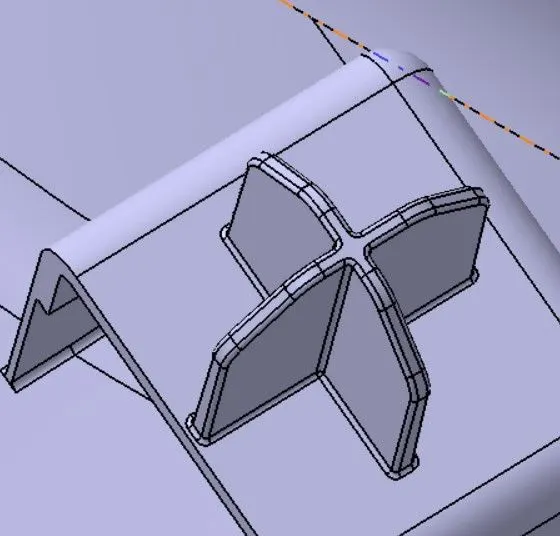
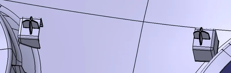
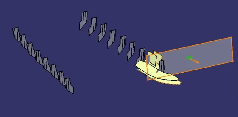
By design rules Dog house and 4-way locator is created as per the master section and made symmetry on other side.
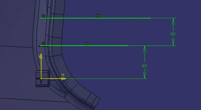
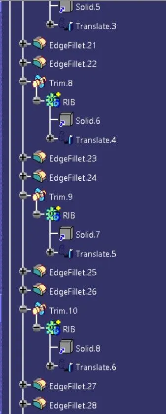
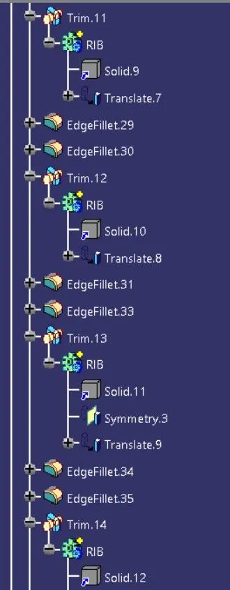
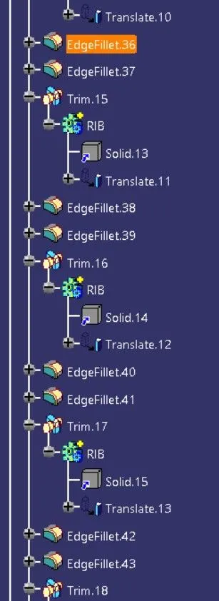
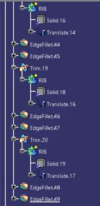
Ribs are created on both sides with 50mm apart for adding stiffness to the B pillar.
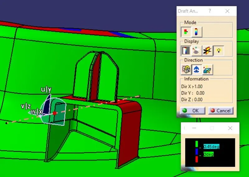
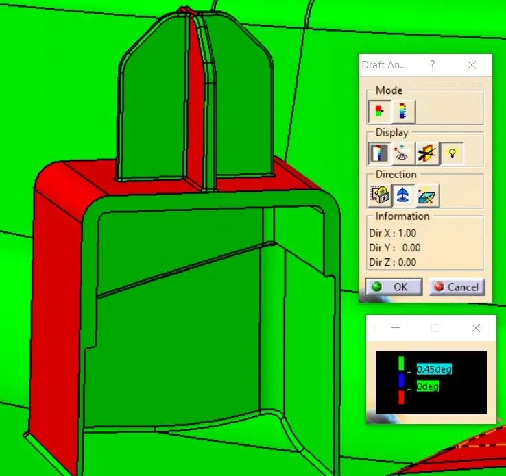
DRAFT ANALYSIS:
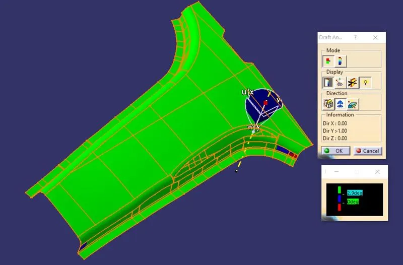
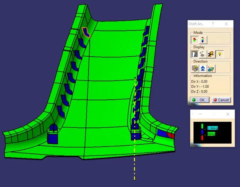
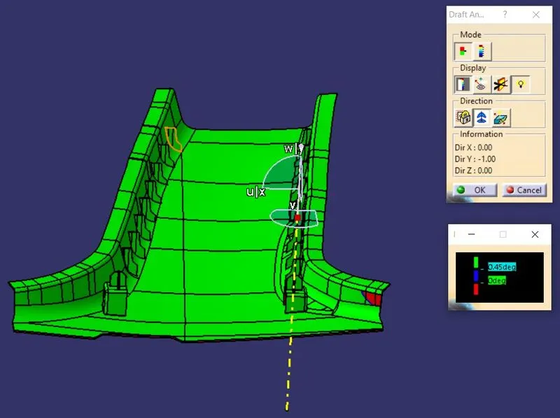
Click the Inset-Analysis -- (Feature) Draft Analysis icon
If material is not on There will be a warning message is shown and then we need to select the material.
The Draft Analysis dialog box is displayed. It gives information on the display (color scale), the draft direction and the direction values.
CLASS A DRAFT ANALYSIS:
SOLID MODEL DRAFT ANALYSIS:
B SIDE FEATURE DRAFT ANALYSIS:
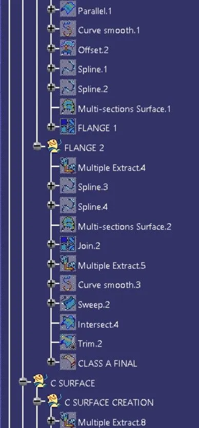
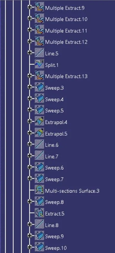
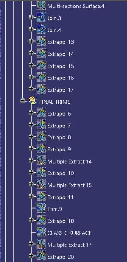
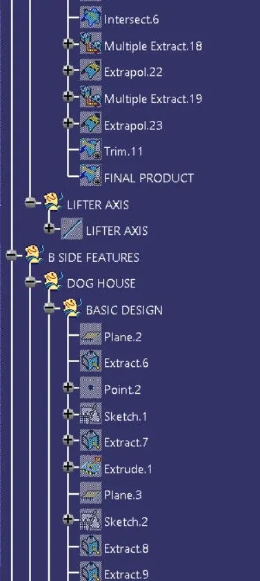
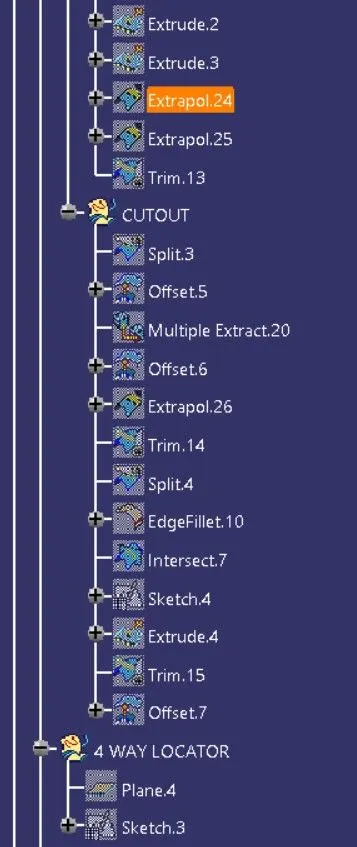
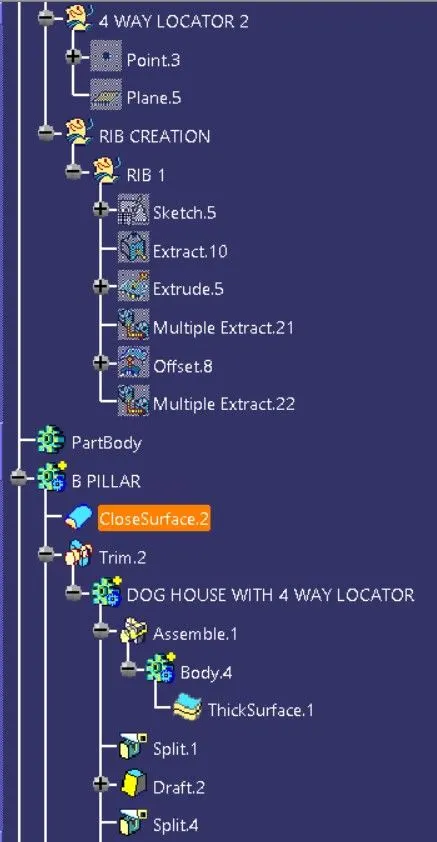
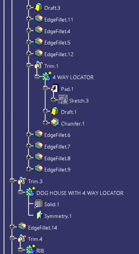
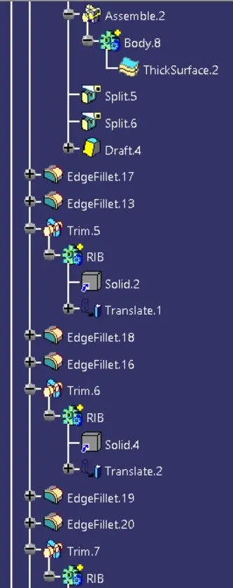
TREE STRUCTURE:
MODEL VIEWS: