Advanced Sheet Metal Design Using NX Cad Challenge_1_Casing Design
CASING DESIGN IN SIEMENS NX CAD
JEEVA R
OBJECTIVE:
To develop a “Casing Design” using different commands and tools in NX CAD.
WHAT IS NX CAD?
NX CAD is an advanced high-end CAD/CAM/CAE software used for designing models etc. It was formerly known as “Unigraphics” owned by Siemens PLM Software.
DESIGN FLOWCHART:
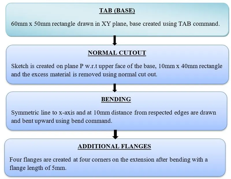
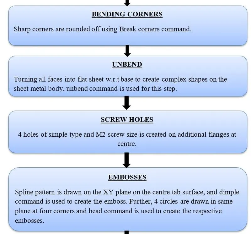
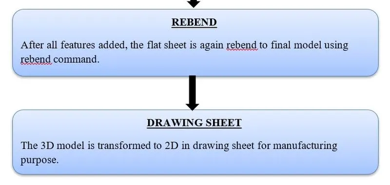
COMMANDS USED:
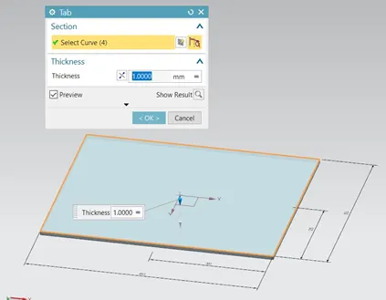
1.TAB:
Tab is used to create base feature of the model on which other features such as flanges are made.
2. FLANGE:
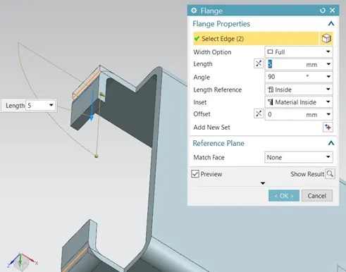
A flange is external or internal ridge or rim for strength as the flange of iron beam. It creates features in any angle and directions as required.
3. BREAK CORNER:
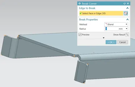
This command is used to round off sharp corners, to avoid injuries.
4. UNBEND AND REBEND:
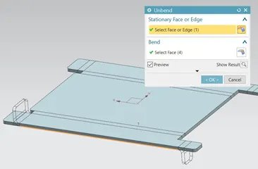
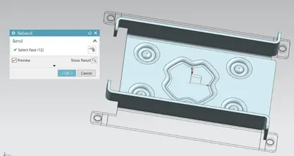
Unbend command is used to flatten the model created to infuse further complex features such as holes, dimple, bead, etc. After, implementing required features then it is again rebend to original model using rebend command.
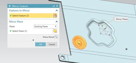
5. MIRROR:
This feature is used to create patterns that are symmetric about particular plane and are of same dimensions and repetitive.
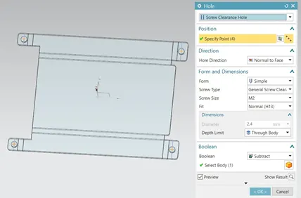
6. HOLE:
It is used to create holes and slots as per design requirements.
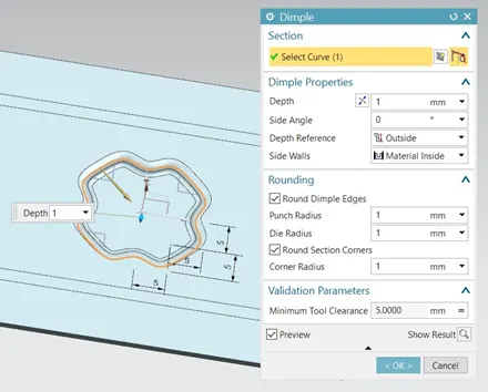
7. DIMPLE:
Dimple is a punch tool used to create emboss over sheet metal parts, this command creates embosses as per the sketch made.
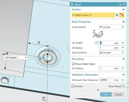
8. BEAD:
Bead is another punch tool used to create embosses over sheet metal, this feature is used to elevate sheet metal parts without flat contact with surface.
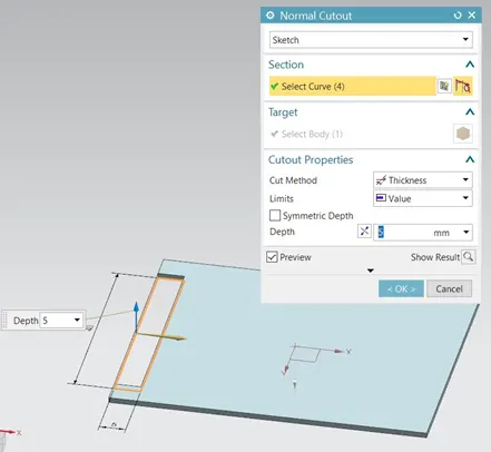
9. NORMAL CUTOUT:
It is used to remove material with defined sketches to facilitate required design.
DIFFERENT VIEWS:
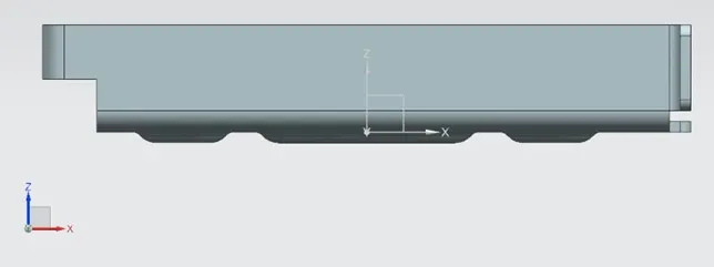
FRONT VIEW:
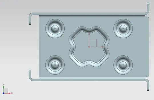
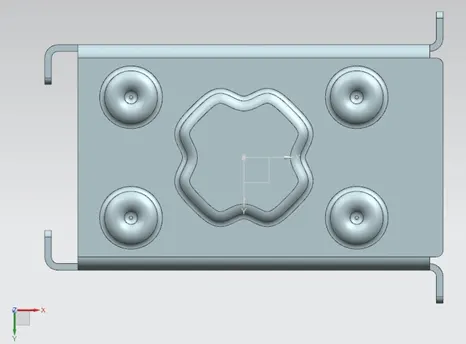
TOP VIEW:
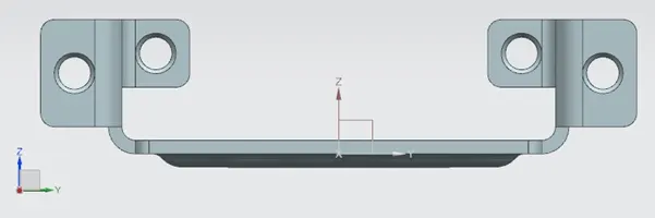
SIDE VIEW:
BOTTOM VIEW:
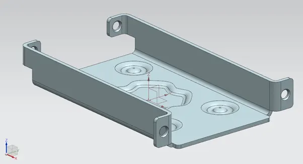
ISOMETRIC VIEW:
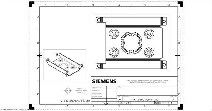
DRAWING SHEET:
CONCLUSION:
Thus, sheet metal casing using NX CAD has designed successfully.