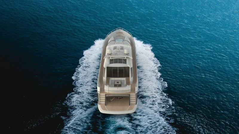
Modelling Of Sunseeker Predator yacht On SolidWorks
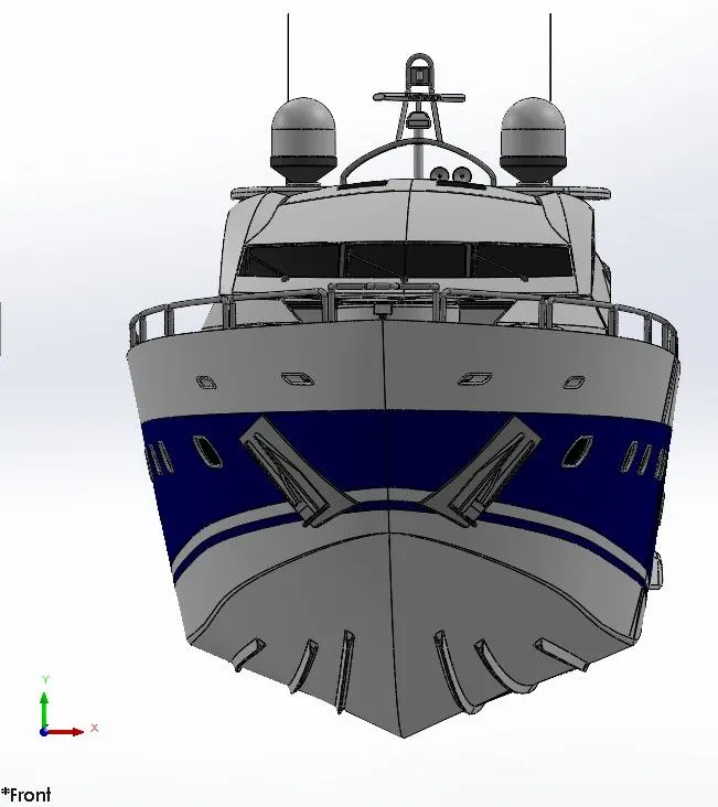
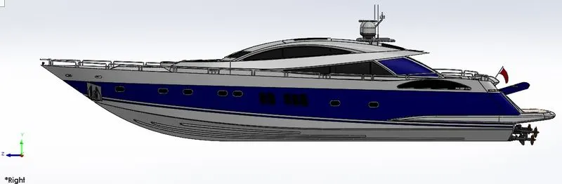
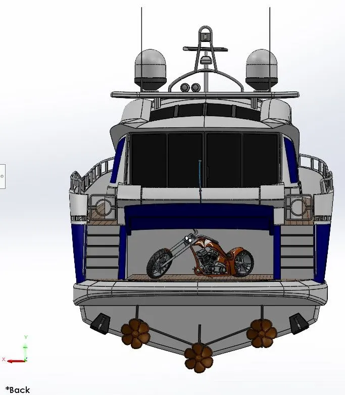
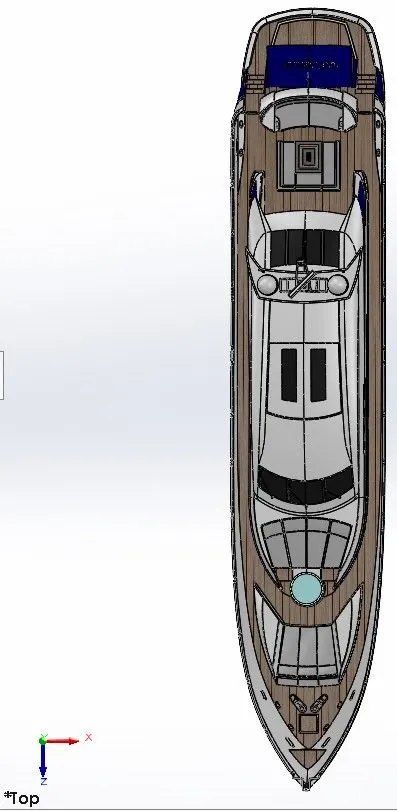
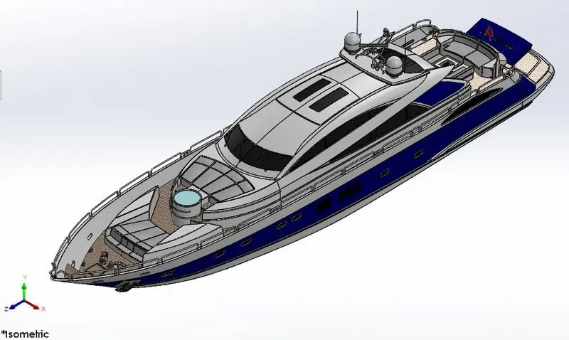
MODELLING OF SUNSEEKER PREDATOR YACHT ON SOLIDWORKS
JEEVA R
INTRODUCTION:
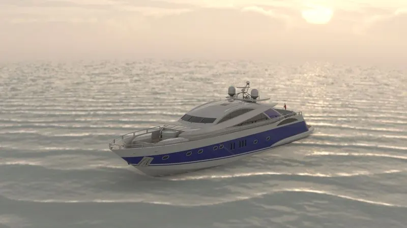
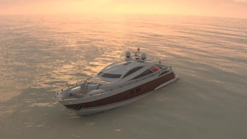
In this Ultimate Solidworks course followed by solid modelling here we are to begin with surface modelling by modelling Sunseeker predator yacht and render the model in Solidworks Visualize.
First, we begin with modelling of different parts of yacht. The different parts of yacht are
- Hull
- Super structure
- Radar mast
- Radar
- Propellor
- Front seat
- Middle Seat
- Rear seat
- Garage door
After modelling parts, we learn to assemble the modelled parts using assembly and after assembly model is rendered using solidworks visualize to get realistic effect of model.
DESIGN APPROACH:
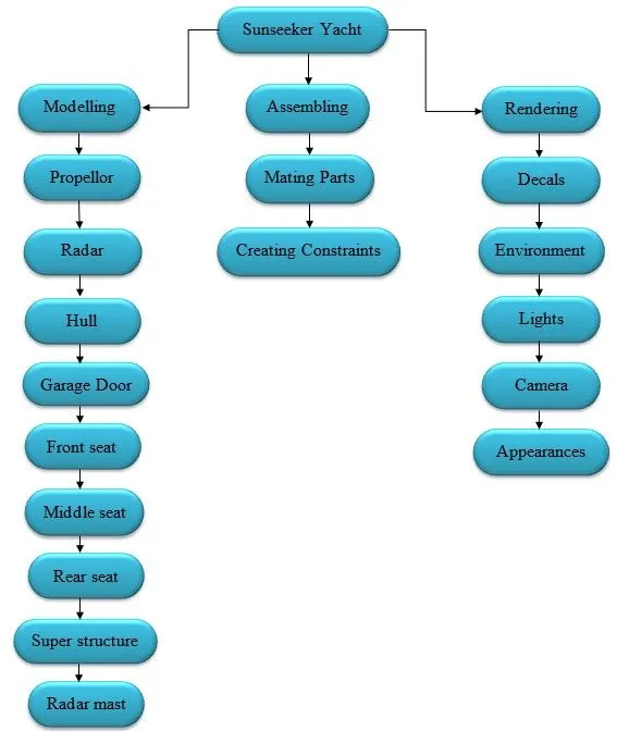
Here we start with Simple and independent parts such as propellor, radar and start with the hull which is the base and reference to all following parts which comes in contact with hull surface. Sequence is as shown in the flowchart below.
FLOWCHART:
TYPES OF COMMANDS USED:
Sketch - Create the sketches and decide how to dimension and where to apply relations.
Features - Select the appropriate features, such as extrudes and fillets to create a solid body where ever required.
Surfaces - Surfaces are a type of geometry that are used to model complex shape and to create solid features.
Assembly - Used to Assemble components modelled by adding mates and relations.
3-D Sketch - Here we can snap to major direction X, Y and Z and constraints are applied in all direction respectively. These are constraints to global coordinate system.
FEATURES USED:
Let’s discuss what are the features and properties used in the entire model to design different parts:
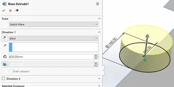
Extrude Boss: Thextruded Boss is the most basic of all SOLIDWORKS features and extrudes a sketch along a straight-line path to add material. As a sketched feature, it requires a sketch before use. Once the sketch has been created, exit the sketch and select the Features tab of the Command Manager. Then, click the Extruded Boss/Base command. If a yellow dialog box appears in the Property Manager asking you to create a new sketch, don’t worry – simply click on the sketch in the graphics area by expanding design tree to use it for the feature. The Property Manager for the Extruded Boss allows you to control starting location, extrude depth and draft for the feature, among several other parameters.
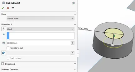
2. Extrude Cut: Similar to the extrude boss feature this feature needs a sketch on the solid body which needs to be removed and required portion is cut to form a desired model.
3. Revolved Boss Feature: Adds material by revolving a sketch around an axis. Remember, once geometry has been created in your model, any flat face can be used as a sketching surface. It is very important to draw an axis in the sketch which needs to be revolved and even temporary axis can also be turned on for selecting axis of revolution.
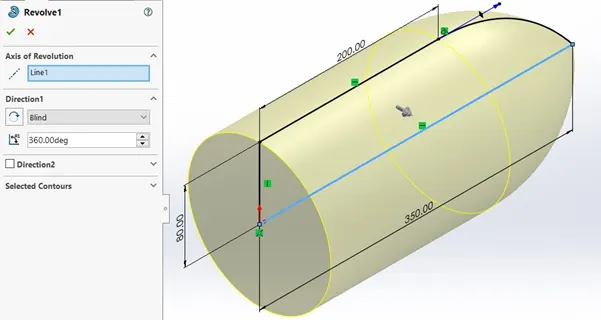
4. Revolved cut Feature: Unlike revolved boss feature this feature is used to remove material by revolving along the axis for a particular sketch created.
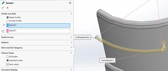
5. Sweep Boss / Sweep Cut: Sweep creates a base, boss, cut, or surface by moving a profile (section) along a path, according to these rules: The profile must be closed for a base or boss sweep feature; the profile may be open or closed for a surface sweep feature.
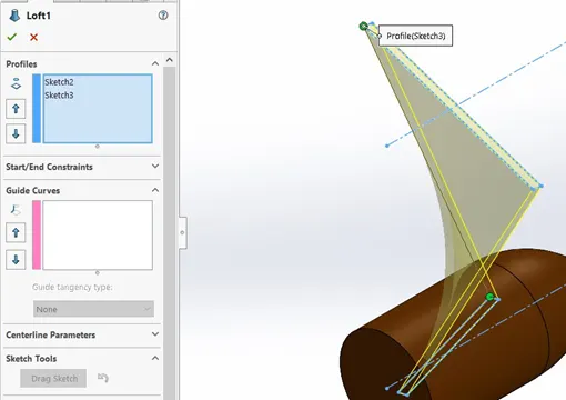
6. Loft Boss/ Loft Cut: The loft feature is an important tool for (surface) modelling in SolidWorks. The loft feature creates a shape by making transitions between multiple profiles and guide curves. This tool is very valuable for modelling complex surfaces. You can do some cool stuff when you use this feature properly.
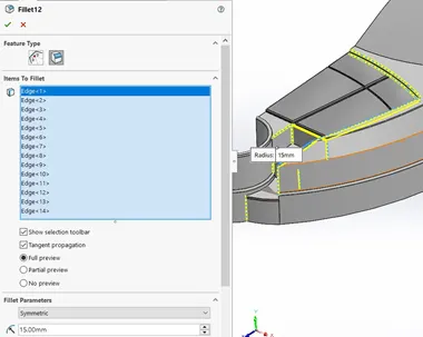
7. Fillet: Fillets are classified as applied features, and as such do not require a sketch to be used. Fillets serve to round off edges and/or corners by adding or removing material, depending on whether the edge is internal or external. It should be noted that fillets of different sizes must be created as separate features. Typically, it is best practice to create the largest fillets first and follow with smaller fillets.
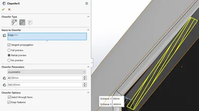
8. Chamfer: Whereas fillets produce rounded edges, chamfer produces blunt edges cut at an angle.
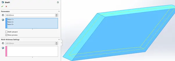
9. Shell: SolidWorks shell tool is mainly used for shelling process, in which the material removed from the inner body of model by keeping small thickness and results a hollow model. Using this tool, you can make either completely closed hollowed model or one face opened type.
10. Combine: This is a cool feature where different geometry are combined into single geometry and also this feature has an option to combine common geometry created from different sketch.
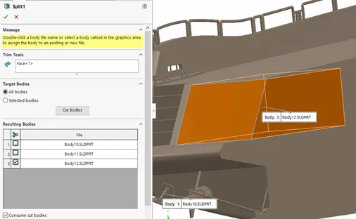
11. Split: This feature is handy for splitting different geometry, parts and also remove unwanted geometry. It requires a sketch and generates various split options according to requirement we can remove the part.
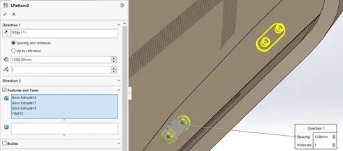
12. Linear Pattern: You can use linear patterns to create multiple instances of one or more features that you can space uniformly along one or two linear paths. Pattern instances inherit the visual properties of the original feature when you select Propagate Visual Properties in the Property Manager.
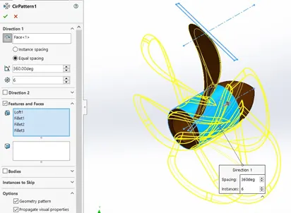
13. Circular Pattern: This feature is handy when specific patterns of part are circularly repeating along particular geometry.
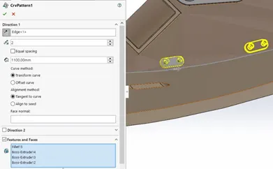
14. Curve driven Pattern: In this feature patterns are made to repeat along the curve drawn and this feature is used when pattern is to be repeated along the curve drawn.
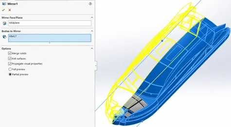
15. Mirror: Creates a copy of a feature, (or multiple features), mirrored about a face or a plane. You can select the feature, or you can select the faces that comprise the feature. Bodies to Mirror: Select a body in a single model or multibody part to create a mirror entity. Multibody parts: Apply features to one or more multibody parts by selecting Geometry Pattern and using Feature Scope to choose which bodies should include the feature.
This feature is handy while dealing with symmetric geometry.
16. Reference Geometry: Reference geometry defines the shape or form of a surface or a solid. Reference geometry includes items such as planes, axes, coordinate systems, and points. You can use reference geometry in the creation of several kinds of features. For example:
- Planes are used in lofts and sweeps to create sketch normal to the path.
- An axis is used in a circular pattern.
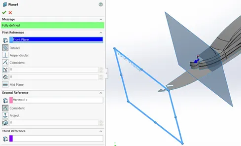
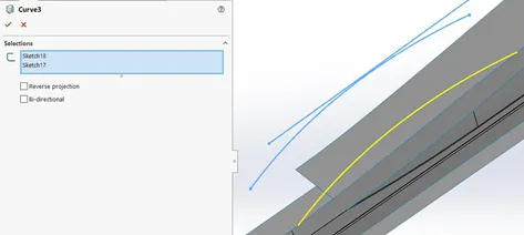
17. Projected Curve: You can project a sketched curve onto a model face to create a 3D curve. You can also create a 3D curve that represents the intersection of two extruded surfaces generated by creating sketches on two intersecting planes. You can create multiple closed or open-contour projected curves from a single sketch. You can also use 3D sketches as input for the Projected Curve tool. Note: the Projected Curve tool does not support projections of intersecting curves.
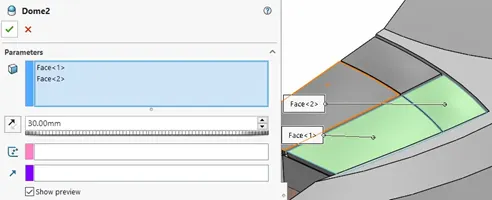
18. Dome: It is used to add smooth and projected surface from planar surface selected with required height oh projection.
SURFACE FEATURES USED:
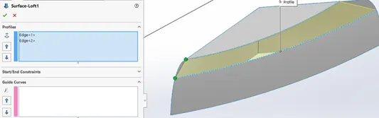
1. Lofted surfaces: Creates a lofted surface between two or more profiles or sketches. Specify start and end constraints and add guide curves to control the path shape.
2. Boundary surfaces: The boundary surface feature lets us to create surfaces that can be tangent or curvature continuous in both directions (all sides of the surface). In most cases, this delivers a higher quality result than the loft tool.
3. Extruded surfaces: Extrudes a sketch or selected sketch contours in one or two directions to create a surface feature.
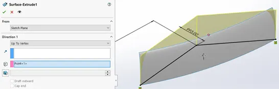
4. Revolved surfaces: Revolves a sketch or selected sketch contours around an axis to create a surface feature.
5. Swept surfaces: It sweeps a closed profile along an open or closed path to create a surface feature. It uses a tangent plane at end of the path so that the path is normal to the swept surface.
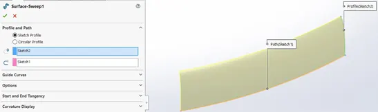
6. Filled surfaces: Patches a surface within a boundary defined by edges, sketches, or curves. We can use constraint curves to fill surfaces and adjust resolution control to improve surface finish.
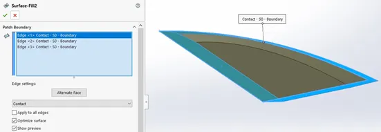
7. Ruled surfaces: Inserts ruled surfaces in a specified directions from the edges. Tangent to surface, normal to surface, tapered to vector, perpendicular to vector or sweep can be selected. We can also trim and knit the surfaces and remove any connecting surfaces.
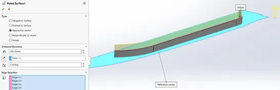
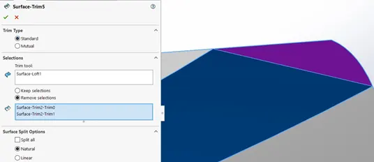
8. Trim surfaces: It trims the surfaces where a surface intersect with another surface, a plane or a sketch.
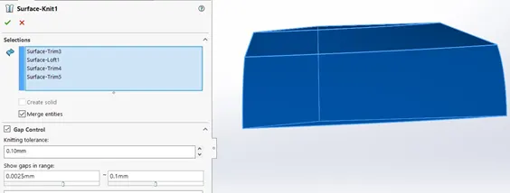
9. Knit surfaces: It combines two or more adjacent, non-intersecting surfaces into a single surface body. The surfaces must joint at an edge. If the resulting knit surfaces encloses a volume, we can create a solid body from property manager.
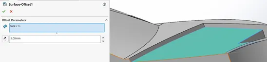
10. Offset surface: offsets surfaces using one or more continuous faces. This tool helps us to create an offset surface with gaps.
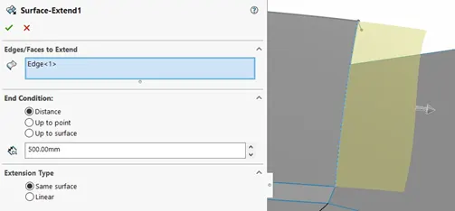
11. Extend surface: Extends one or more edges or faces on a surface, based on end conditions and extension type.
12. Split line: The split line tool projects an entity (sketch, solid, surface, face, plane or surface spline) to surfaces, or curved or planar faces. We can split curves on multiple bodies with one command.
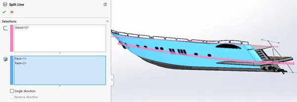
13. Split point: We can split a sketch entity to create two sketch entities. Conversely, we can delete a split point to combine two sketch entities into a single sketch entity.
As we have completed discussion of how the features work under solidworks let us see the application of the features in the yacht that we have built. We are going to discuss part by part as shown in the flowchart.
PART MODELLING:
Blueprint: A blueprint is a reproduction of a technical drawing or engineering drawing using a contact print process on light-sensitive sheets. A blueprint is a guide for making something, it’s a design or pattern that can be followed. They were easier to read and faster to make.
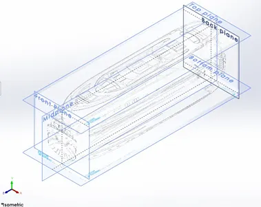
The above blueprint was used to model the yacht in a fully defined constraint. For setting up the blueprint the sketch pictures option was used and the different blueprints were placed at required planes.
All the parts modelled are mirrored about mid plane to make effective and easy modelling of patterns except propellor.
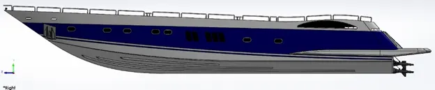
Hull: A hull is a watertight body of a ship or boat. The hull may open at the top or it may be fully or partially covered with deck. The line where the hull meets the water surface is called the waterline. The hull of the ship is most notable structural entity of the ship. To define the hull, it can be said that it is the watertight enclosure of the ship, which protects the cargo, machinery and accommodation spaces of the ship from the weather, flooding and structural damage.
Here we begin with modelling the outer surfaces according to the blueprint using various surface features and later different parts, patterns associated with the hull are modelled with reference geometries according to the blueprint. The parts associated with hull are aft, anchor, beam, berth, bow, bridge, cabin, cleat, deck, draft, gallery, gunwale, hatch, helm, keel, line, port, porthole, rig, starboard, stern. Later appearances and decals are added to enhance the model.
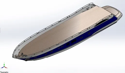
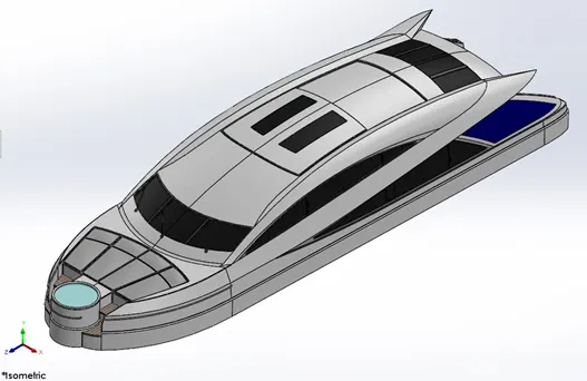
Super structure: A super structure is an upward extension of an existing structure above a baseline called ground level and it usually serves the purpose of the structures intended use. A super structure is a decked structure on the freeboard deck, extending from side to side of the ship.
Here the deck surface is imported from the hull for reference to model the super structure. Surfaces are created using various surfaces commands such as loft surface, sweep surface, ruled surface, trim and knit surface according to the blueprint. After surface modelling the model is converted to solid model and detailing’s such as window frame, door frame, bed, seat, wiper are made. Then appearances and decals are added to get a realistic look.
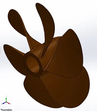
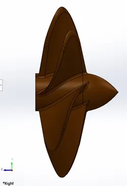
Propellor: There can be one or more than one propellor in the ship. It is the most important part of the ship without which a ship can’t move. So, the main function of the propellor is to propel the ship in forward direction by producing thrust on water. It works on principles of Newton’s third law of motion and Bernoulli’s theorem.
First the sketch is drawn and revolved then blades are made by loft feature, fillets and circularly patterned around the revolve. Extrude cut is made on revolve for opening to attach shaft from engine. Finally, appearance is added to the propellor.
Garage door: A garage door is a large door on a garage that opens either manually or by an electric motor (a garage door opener). Garage doors are frequently large enough to accommodate automobiles and other vehicles.
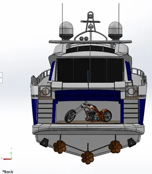
This is modelled using the part splitted from hull. First it is extrude cut to obtain the shape of the door and it is shelled inside with fillets. Later provisions are provided for fitting it with the hull. Finally, text and appearances are added to make it classy.
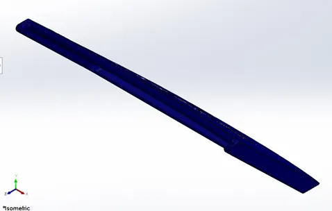
Radar: Marine radars are X band or S band radars on ship, used to detect other ships and land obstacles, to provide bearing and distance for collision avoidance and navigation at sea.
First sketch is drawn to shape and extruded. Next flange with fasteners is modelled and mirrored about midplane. Finally, text and appearances are modelled.
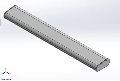
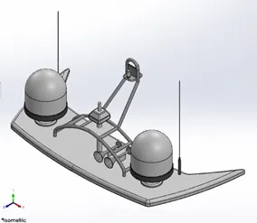
Radar mast: A mast is a vertical ship structure mounted on top of bridge and forward of the forecastle towards the ship’s bow. It accounts for the support platform for ships derrick and hold necessary equipment’s such as radar, navigation light and ships horn in case of forecast.
The base is drawn as per blueprint and extruded. The other components are modelled and mirrored about midplane to obtain complete structure. Finally, appearances are added accordingly.
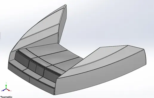
Front seat: Front seat is a combination of two seats back-to-back and sun pads for rest. Lounge seats can also fully recline right back to make it easier for you to kick your feet up and get more comfortable. The front seat is placed before the super structure.
The outer structures are made using different surface commands which is modelled according to the blueprint and made as single solid object. Next, seats are modelled in front and back which is mirrored as whole about the midplane to obtain a required model. Finally, appearances are added to seats and base accordingly.
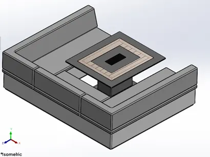
Middle seat: The middle seat in our model is placed just behind the super structure. It is provided with luxury table to dine out. It can also be used to have casual meetings with co-passengers.
Here the base is drawn and extruded which is further modelled to seats. Next, the table in middle is modelled and as a whole it is mirrored about mid plane. Then it is concluded with applying decals and appearances accordingly.
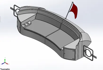
Rear seat: The rear seat is placed at the end of the deck surface. The rear seat consists of locker racks and steel doors for our stairs. The flag is also placed behind the rear seat hence it’s the end part of our yacht. To have a nice view from the yacht while having a drink the rear seat was also provided with a slots to rest the glass or mug.
The main body is modelled using surface features such as sweep, loft, fill, ruled, trim, extend and knit options which is further turned to solid body. Next, seats are modelled and holding palettes for glass are made. Further, door for locker and gate for steps are made. After modelling completely all are mirrored about midplane. Later flagpole and flag are modelled as per blueprint. Finally, appearances are added to different features.
ASSEMBLY:
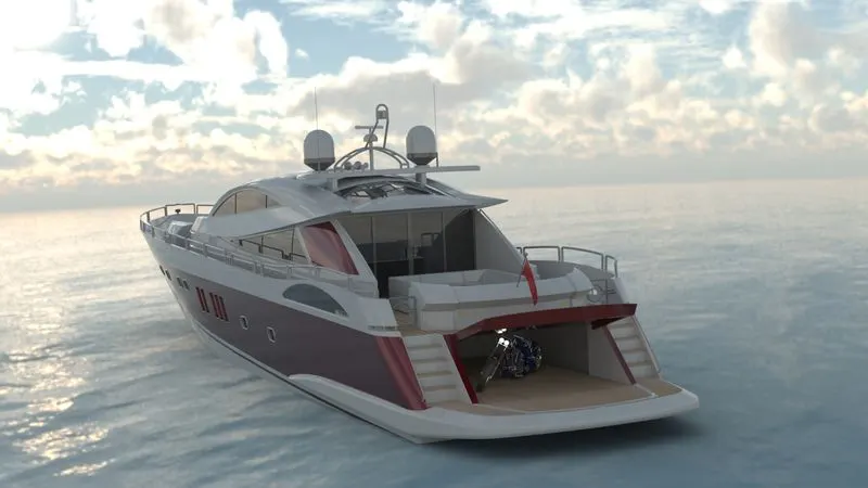
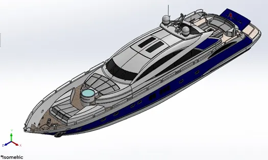
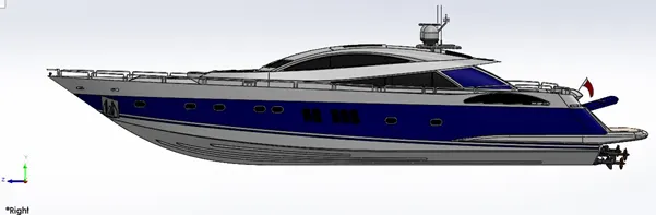
Once all parts are modelled assembly window is opened and parts are inserted into the assembly beginning with hull. Here, hence we are modelling with deck surface as reference all parts are automatically fixed to desired position except propellor, radar and garage door. Later, these three are inserted and matted according to the requirement. Finally, American chopper modelled in previous project is inserted and placed inside the garage accordingly. Then assembled yacht is processed for rendering.
Reference for American Chopper: https://skill-lync.com/projects/photo-realistic-rendering-343
RENDERING:
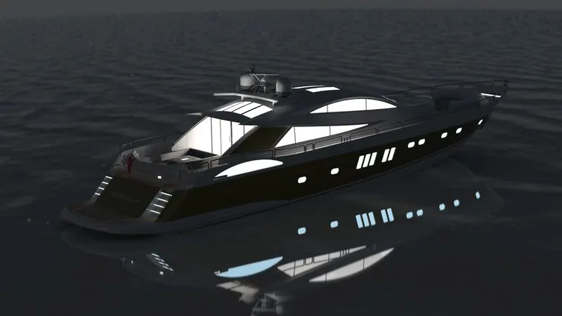
After assembly model is imported to Solidworks visualize where it is setup at desired environment, lightings, camera and appearances. Here various environments and backplates related to yacht such as ocean environment, night environment, cruising yacht environment are used to obtain realistic yacht model. Different renderings are made in various environment to enhance the model and make it professional.