Week 9 - Project - Master Section Development
MASTER SECTION DEVELOPMENT
CLASS A Surface of a B - Pillar is given. Class B and Class C Surfaces are to be created and Draft analysis is to be made on the created part.
Initially the Class A Surface was checked visually and also the boundaries are viewed to verify whether the surface is neat with a single boundary or it has defects in it.
If the Class A surface has some errors, it should be reported to the FEA team, Here the problem is solved by ourself.
The suface is solved and checked for boundary, It should result only one boundary.
The Tooling axis is created by creating point on the surface and at angle normal to the surface.
Using the extract option the two boundaries of the Class A is extracted and Flange should be created on those sides, So the extracted boundary is swept to the angle of the flange using the multisection as the reference.
After creating the flange on both the sides of the Class A surface, The surface is offsetted to the thickness of the given component which is 2.5mm.
The offsetted surface boundaries are extrapolated to a certain distance for trimming it with the C surface.
The C Surface is created by extracting the boundary of the Class A Surface. The Extracted Surface is Swept with a Draft angle of 3 degree in the direction of the Tooling Axis.
The obtained C surface is trimmed with the initially offsetted surface which is our B Surface.
The surface body is obtained.
Moving to Part Design using Solid Fill, Convert the Surface body to Soild body.
The base of the B - pillar is obtained.
Now the B Side features are to be created.
Using the multisection as referenece draw a sketch on the multisection and surface extrude it. Now the B surface is extracted and both are trimmed together.
The Dog House's surface is now thickened for 0.8 mm.
A Four way Loactor is created on the Dog house.
By using the Dog House's top face as reference, A plane is created and sketch for the four way locator is made on the plane and the sketch is paded using the thicken option.
Then the four way locator is union trimmed with the Dog House. Then it is mirrored by creating the plane in the middle of the B Surface.
The body of the Dog House is Union trimmed with the Solid Body .
The Ribs are created by sketching on the side of the B Pillar using the same plane which we used for the four way locator.
Multiple Ribs are created both the sides having a distance of 50mm between them.
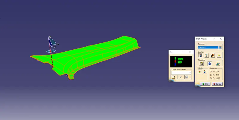
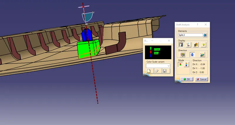
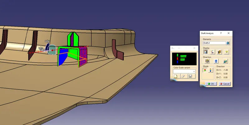
Now the obtained body is Draft Analysed using the Tooling Axis. For the Dog House the Side Core axis is used.
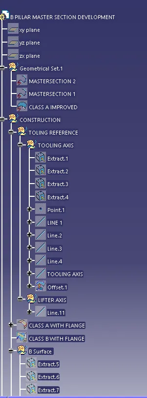
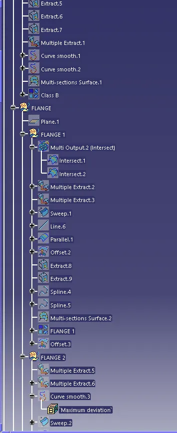
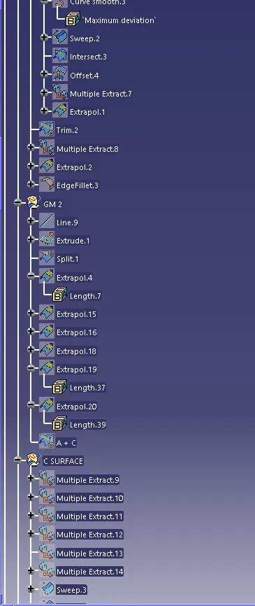
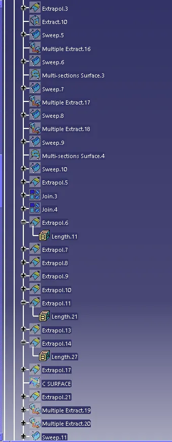
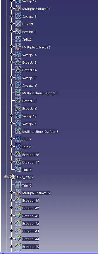
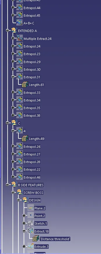
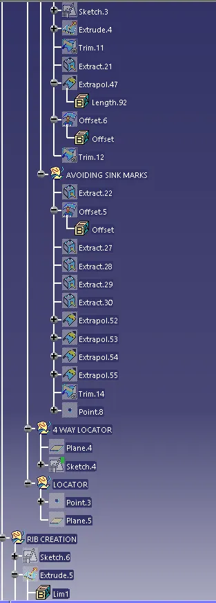
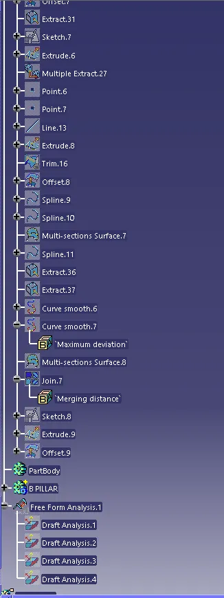
FEATURE TREE
FRONT VIEW
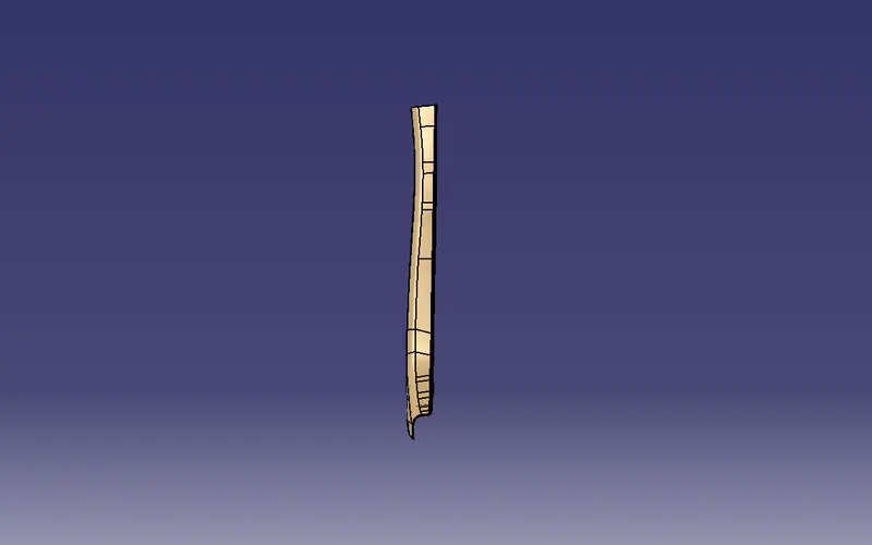
TOP VIEW
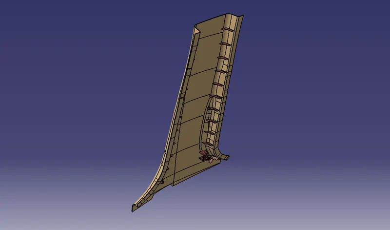
SIDE VIEW
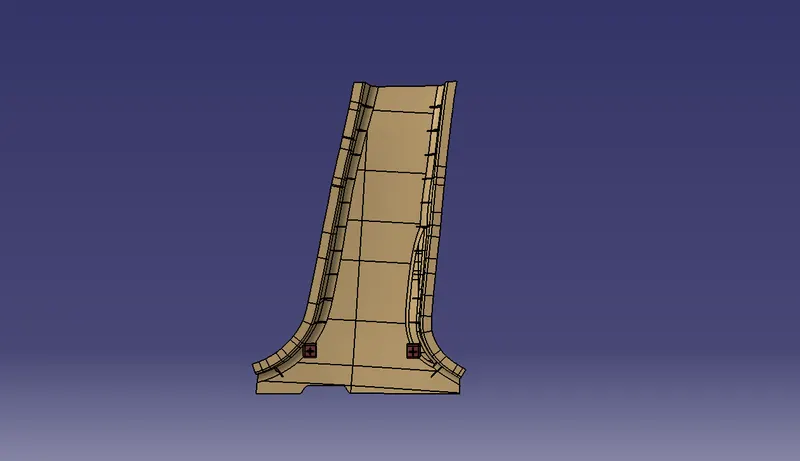
ISOMETRIC VIEW
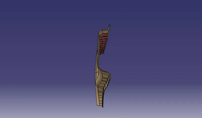
DRAFT ANALYSIS