Week 8 - Challenge 2 - Base Bracket Design
INPUT: CLASS A SURFACE of Brace Bracket.
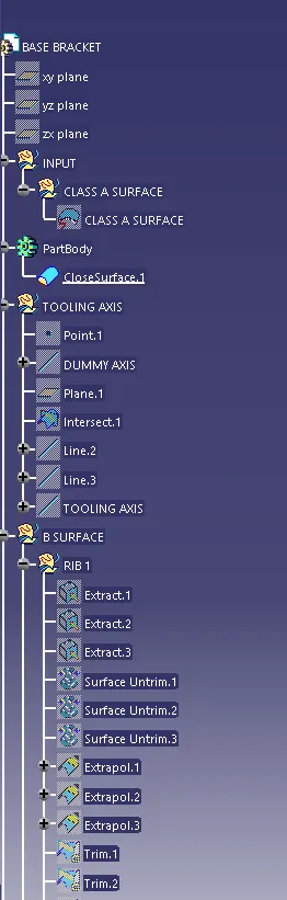
Initial process was to decide the tooling axis. To find the tooling axis first visual inspection was made on the given CLASS A SURFACE and then intersection of each face is obtained and the line extracted from the face which is to be drafted is extended and the two lines are bisected and the bisecting line is obtained.
The same process is carried along the other plane too and the bisecting line is obtained.
Then these two bisecting lines are bisected together and the new line is obtained .
The final line that is obtained is the tooling axis of the part.
The tooling axis can be published so that the access will be much easier to the tooling axis.
CREATING THE B SURFACE
B SURFACE is obtained from the Class A Surface by offsetting the Class A Surface to the given thickness of the part.
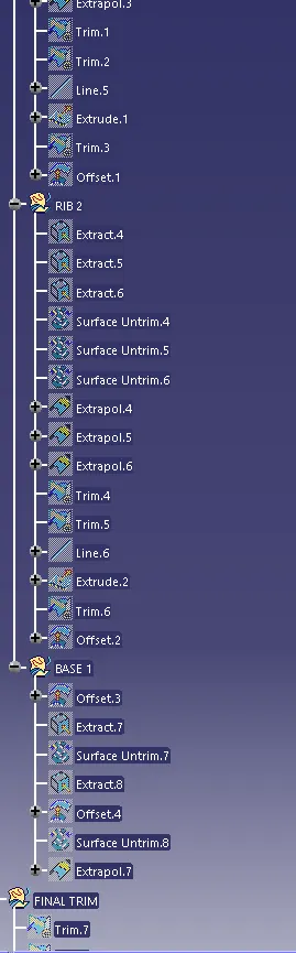
The last part of the B Surface was to add fillets, Here fillets of the Class A Surface were measured using the measuring tool and the filleted value of the B Surface was given by adding both the offset value and the fillet value to get a even gaph between the Class A surface and the B Surface.
C SURFACE
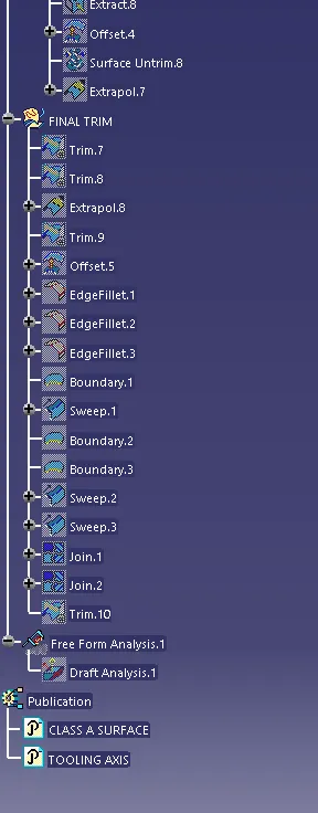
Initially the boundary of the Class A surface is obtained using the boundary tool and later the boundary is surface extruded to some extent more the the thickness of the part and then trimmed with the B Surface.
In Part Design using the close surface option the soild part is made out of the surface body.
DRAFT ANALYSIS
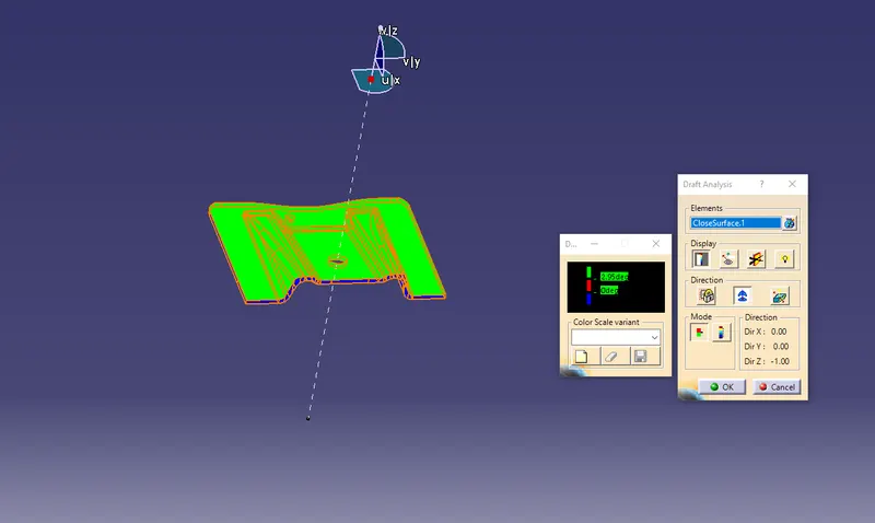
Draft Analysis of the obtained solid body is made and the results are attached below.
FEATURE TREE
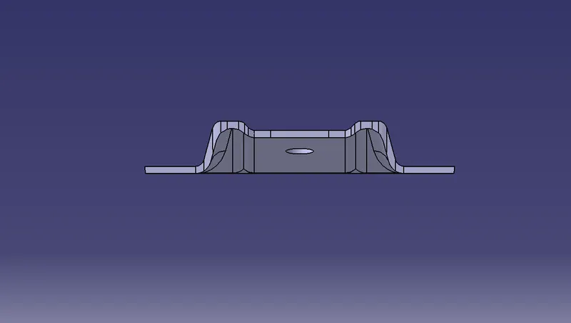
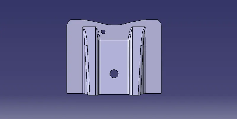
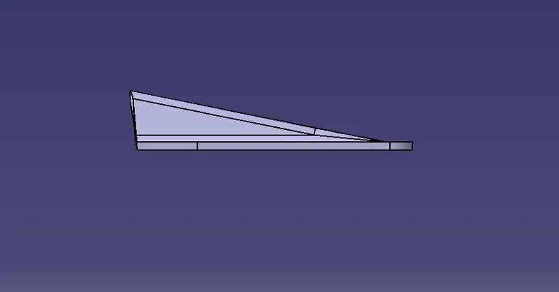
VIEWS OF THE FINAL PART
DRAFT ANALYSIS