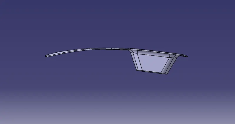
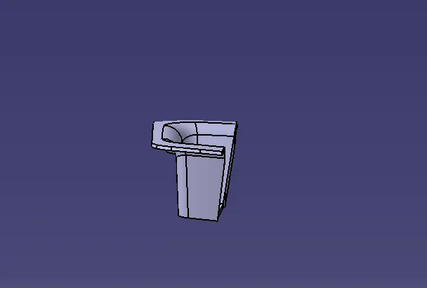
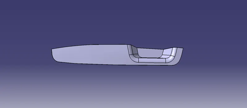
Week 8 - Challenge 3 - Switch Bezel Design
The class A Surface was the input and the thickness of the part to be obtained was 2.5mm.
Initially Visual inspection is done on the class A Surface to determine the tooling axis of the object.
After the Visual inspection, to ensure the accurate tooling axis, An axis system is created at the center of a surface and the axis that to be drafted are selected and the intersections are made accordingly.
After obtaining the intersection the lines to be drafted are extended and those lines are bisected so that the bisecting line is obtained.
The same step is carried fo the other axis.
Then the obtained bisecting lines from both the axis is bisected again to obtain the tooling axis.
The Tooling Axis is published for easy reference.
Creation of Class B Surface :
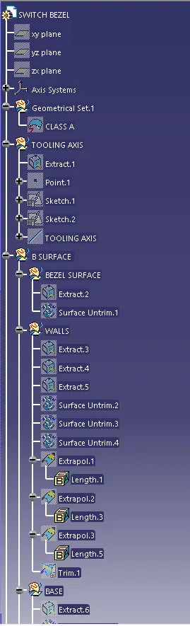
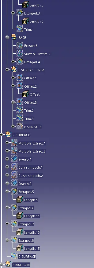
The Class B Surface is created by extracting the class A surface and untrimming it. Then the untrimmed sufaces are offsetted for the thickness value.
The offsetted surfaces are trimmed to obtain the Class B Surface.
Then the fillets are applied to the edges
Creation of Class C Surface :
The Class A Surface boudary is used to extract the Class C Surface. The Tooling axis is chosen for the direction and the Draft angle is set outward to avoid the flash while manufacturing the product.
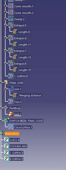
Then the Class A surface is joined with the Class C surface and the B surface is trimmed from the obtained surface.
Final Product :
The Final product surface is made into solid using the close surface option in the part design section.
Draft Analysis:
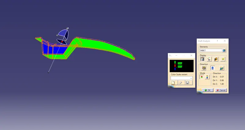
The draft is analysed for the obtained product.