Week 9 - Project - Master Section Development
Aim:
The aim of the project is to create a solid body of the B pillar from the input provided as the class A surface and attach attachment features for fixing the component at appropriate position with the main component following the OEM design standards using CATIA V5 software.
OBJECTIVE
PILLARS IN CAR
Pillars are the vertical or nearly vertical supports of a car's window area or greenhouse—designated respectively as the A, B, c or (in larger cars) D-pillar, moving from front to rear, in profile view.The consistent alphabetical designation of a car's pillars provides a common reference for design discussion and critical communication
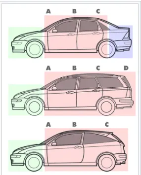
The B pillars are sometimes referred to as "posts" (two-door or four-door post sedan
B-Pillar
The B-Pillar Is The central Pillar Of The car. This Pillar Is Actually a Sheet Metal Part Which Is Welded In The Biw Of The car. The B-Pillar Trim Is Attached To The B-Pillar And Improves The Aesthetic Look Of The car. Mostly The Trims Are Manufactured By The Injection Molding Process. The Design Of The B-Pillar Is carefully Done To Make The Part Manufacturable And Usable In The Interior. While Manufacturing a Part Through Injection Molding a Lot Of Defects can Occur On The Plastic Part Which Will Destroy The Look Of The Panel. The Design Has To Made In Such a Way That All The Errors can Be Rectified.
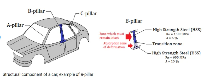
GIVEN
CLASS A
MASTER SECTION
MASTER SEcTION
Master section is predefined model of 3d design.i.e also called Styling of cLASS A SURFAcE.
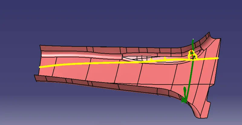
in this fig. class A surface and two are master section
TOOLING AXIS
Tooling axis is the direction of that model pull a part in the injection molding.
The steps followed creating tooling axis.
-A Reference Point Is created Along The Surface Zero And New Axis System Is created
-The X Direction And Y Direction Along The class A Were Used To create Tooling Direction
-Finally The Tooling Axis Is created By Bisecting The Two Lines And It Is Published. class A Surface As Input Using Surface Operation commands class B Is Developed
-The Tooling Axis Determines The Direction Of class c Boundary Swept With Draft Direction.
-When Viewing From Tooling Direction Normal All The Parts That Are Drafted Should Be Visible So It Gives An Rough Idea To Determine Product Manufacturing In Injection Molding
In B Pillar Model There Are Two Tooling Directions One On Main Tooling And Other On Lifter Side That Is Used To Eject The Parts During Injection Modling
Lifter Axis Is Used Because The Attachment Feature Is Bounded By close Walls
cLASS A surface
check the class A surface boundary and its improved from previous
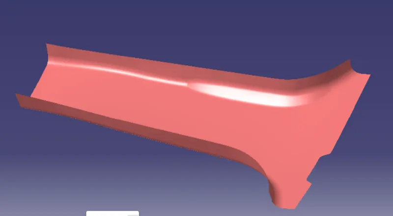
B SURFACE WITH FLAGE
-The next step is to design B Surface for the input which is usually the surface where all engineering aspects and support creations are done.
-The B Surface creation Is Performed Using Surface Operations In catia Which Is An Offset From class A With Dimension Proportional To The Thickness Of The Part
-In B Pillar design The B surface Is offset 2mm from the input which is the thickness of the part
-The offset surface leads to surface degenerations if rapid change In curvature Or surface continuity
-Low Radius Of class A
-conic Or styling fillets
-The Remedy is to untrim, extrapolate and trim or create surfaces using multi surface option and join
FLAGE CREATION
- According to the master section, the B-Pillar has flanges on both sides. The flanges have to be included in the design and the class A And class B Surface has to be modified. The surfaces should match the master section.
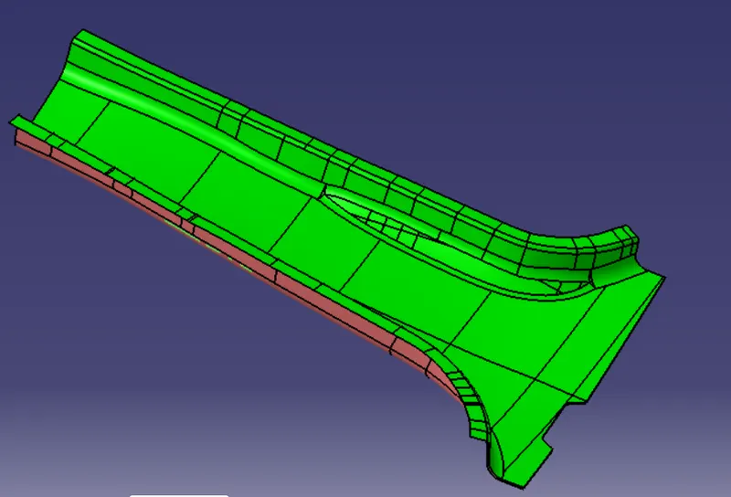
C SUFACE CREATION
The next step is to from the C surface which is an intermediate surface between A and B and is used to give the closed surface appearance To the Design.
The C surface is swept using the profile as boundary line Of class A which is the guide curve with a subtype along Draft Direction.
The direction Of the sweep is the tooling direction formed earlier.
The Draft Angle for The sweep operation is provided which is 3 degree and surface is swept for length above the thickness of the specified part.
The C surfaces must be drafted Outwards from The A Side To Avoid The Parting Line along The A surface.
The C surface is refined using smooth curve options to remove the complexity and patches along the swept surface. Finally the class A And class C surfaces are joined together and connexity of surfaces should less than 0.003mm and The surfaces are merged. C surface merged with Class A
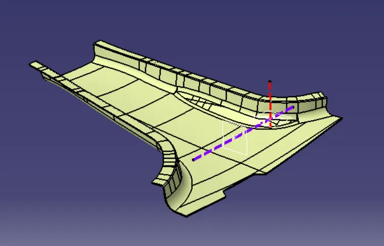
CLOSED BODY CREATION
-The Merged Surface Is Then Trimmed With B Surface To Form The Closed Surface.
-The Closed Surface Is Then Validated To Find The Irregularities Along The Edges And Imperfections Along The Edges Were Then Corrected Using Operation Like Extrapolate And Surface Trim
-This Closed Surface Is The Outer Skin And Finally The Part Is Formed By Closed Surface In Part Design
-The Final Part Is Measured To Validate The Uniform Thickness Of The Part Especially Along The Filleted Edges.
-The Uniform Thickness Ensures That The Part Created Doesnt Form Sink Mark And Flow Lines Along Class A
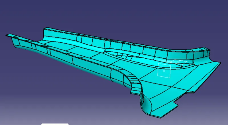
Attachment features
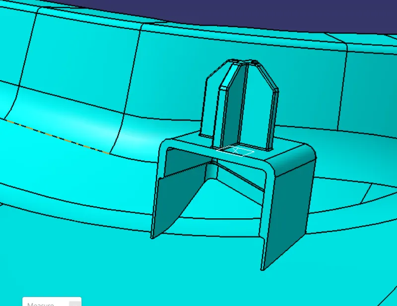
1.Dog house with four way locator
2.Rib
Dog house with four way locator
Using The Master Section The Doghouse Is Created And Then Part Modelled Using Thickness Option
-The 4 Way Locator Is Formed Above The Dog House Which Locates The B Pillar Towards The Mating Surfaces
-The Thickness Of The Connecting Surface Towards B Side Should Be 40% Off The Main Thickness
-The Walls Are Drafted With Min 0.5 Degrees Along The Main Tooling Direction
-The Attachement Feature Created Needs a Seperate Tooling Axis To Clear The Part Hence a Lifter Axis Is Used
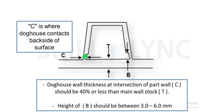
-Four Way Locators Are Tapered Along The Edges To Create An Entry Point For Locators And The Locator Walls Are Drafted Along The Main Tooling Direction.
The Walls Are Minimum Of Above 0.4 Times Of The Total Thickness To Avoid Shot Incapacity During Plastic Product Creations And The Apex Walls Are Ensured To Enough For Creation Of Parts.
The dog house four way locator
Ribs
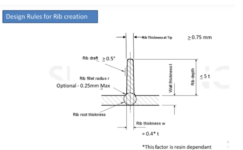
Ribs Provide Stifness To The Parts And Can Be To Impart Thougness Whthout Increasing The Part Thickenss And Are Locators And Provide Allignment To The Mating Parts.
The Design Rules For Two Way And Four Way Fixtures ;
-Rib Wall Thickness Should Be 0.4 Times Of Thickness Of The Part.
-The Drafted Walls Of Rib Should Be Within 0.5 Degrees.
-The Top Height Of Rib Should Be At Least 0.70 Mm Thick To Allow The Molten Plastic To Reach The Top To Avoid Short Shot.
-The Thickness Of The Rib, Fillet Radius, Draft And Rib Root Thickness Are Measured And Are Withing The Design Specifications.
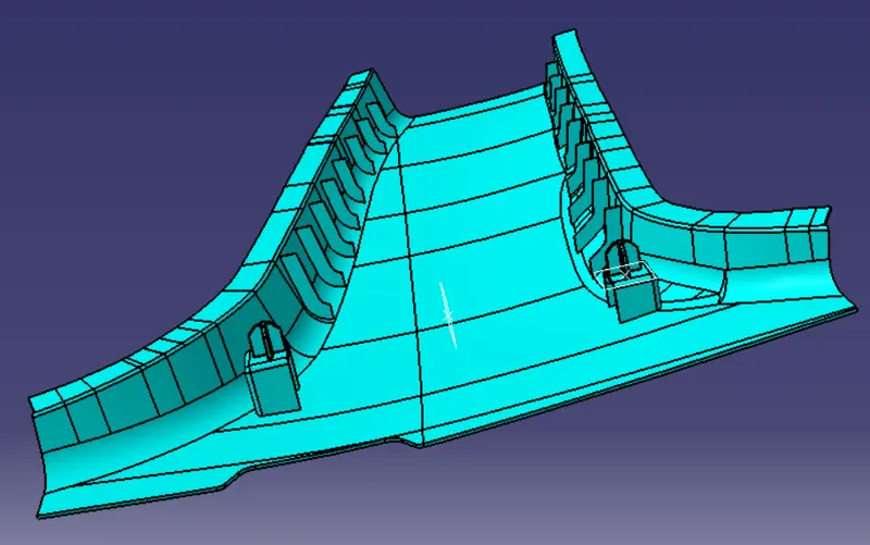
-In B Pillar The Ribs Are 50mm Apart On Both Sides
-Thus B Pillar Cover Is Surface Development is Completed And Attachment Features Are Added.
-It Should Be Noted That The Fixation Of Bolt Locators Always Follow 3-2-1 Taylor Principle.
-Translational Movements Along X,Y,Z Axis (Positive And Negative)
-Rotational Movement Along X,Y,Z Axis (Clockwise And Anticlockwise)
-The Improvement In Given B Pillar Could Be An Addition Of Another Dog House At An Extreme End To Satisy The Taylor's Principle And Thermal Stakes Are Provide That Arrests All Degrees Of Freedom And Completly Fits The B Pillar Part
CONCLUSION
tooling axis is a created and open athestic class A SURFACE IS developed in closed surface with all plastic design rules.
create b piller of car body