Week 9 - Project - Master Section Development
MASTER SECTION DEVELOPMENT
AIM: to create the class be surface ,c surface from the given class a surface and b side features to the component .
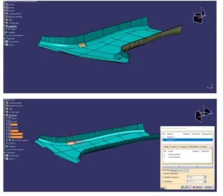
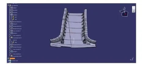
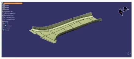
firstly ,the connectivity of the given class a surface must be checked and ensure that there are no gaps between the surfaces
it is clear crom the images in the below are contineous with any gap betwween them.
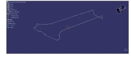
we can feature dissemble the boundary so that the continuity is the clearly visible
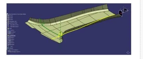
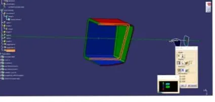
create the tooling axis from the given clas a surface
- tooling axis direction is the diection in which the core and cavity open
- the selection of tooling direction depends upon the prodect and the features of the prodect.
the tooling direction is selected by visuall checking a part and in such way that there are no additional side cores equired for the modelling process
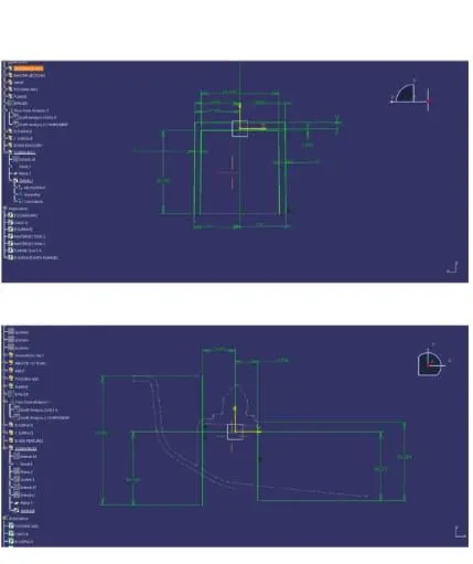
the tooling axis of the component and the tooling axis with the reference eithe master section provided
the tooling axis created by bisecting the lines of te master section
class b surface
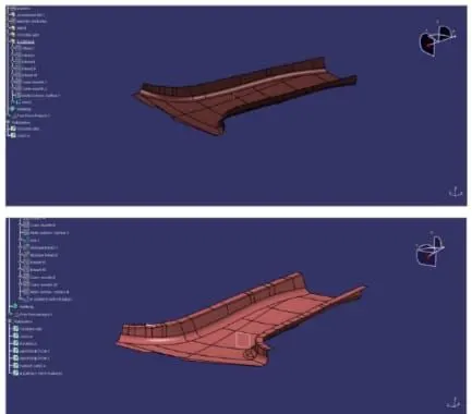
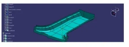
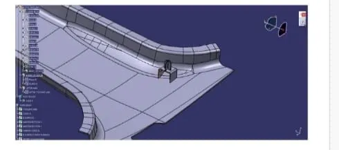
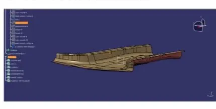
it is a surface that is bellow a creation thickness from the class a surface the engineering features of the product are on the class b surface while the class asurface is the styling syrface the class a surface is the offset by the 2 mm to form a class b surface
the gap between the off set b surface is cleared using the multy section solid the the final class be surface is the formed the image in the below image section
class c surface
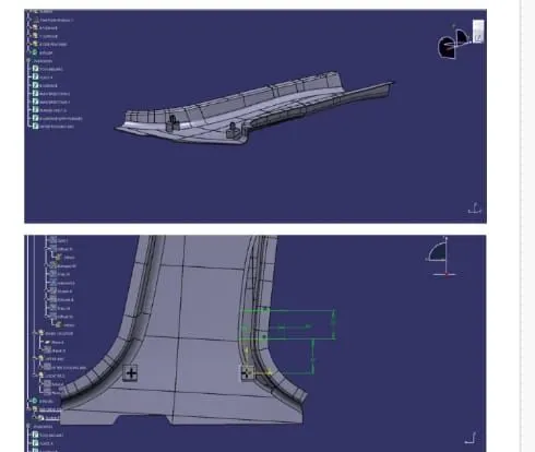
the c surface creation is the surface is used to join the class and class b surface the c surface is created with respect to the tooling axis using the sweep comand
the class surface is trimmed with the class c surface b side features alos created
draft alalysis
a minimum 3 degree is maintaind for the draft
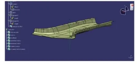
images of the cat part: