Week 8 - Challenge 3 - Switch Bezel Design
SWITCH BEZEL
AIM: create a swich bezel plastic component through the given class a surface
THERRY:
TOOLING AXIS: tooling axis is the direction in which the component wlii be expecting after the molding process is completed.The rules of selecting an ptimum of the tooling axis for any particular component is as follows
- the direction of the tooling axis should be clearing the maximum ni of portions of the component once the modelling process is completed
- the direction of the tooling axis should be selected such that the no of sides cores reqired should be minimus as insecting side cores causes a rise in production cost
DRAFTING :draft is the inclination given to the any particular plastic components cavaty wall in order to achieve easy ejection ,once the proces is completed
- consider that the draft angle between the plastic component and the core is zero. when the molten plastic inside the cavaty cools,it stick to the walls of the core
- buring such zero draft condition .the ejection of the plastic component causes friction between them which might bring damage to both the core and the component
- this damage further leads to inefficiency in the production& and also afectthe products surface finish. hence a minimum of percent 1degree draft is provided to help in releasing the components
- however 3 degree draft is widely accepted as a norm in the industry
PREREQUISITES BEFORE CREATING THE TOLING AXIS AND PERFORMING THE DRAFT ANALYSIS
- ensure that the class a surface imported should be a imported surface .
- this can be checked using the boundary tool in the operation tool bar
- if the surfaces are dissambled ,join them usin join comand which also found in the operations tool bar
CREATING ANY COMPONENT FROM CLASS SURFACE (OVERVIEW)
- decude a suitable tooling axis direction and creating the tooling axis
- perform draft analysis for analysing wheather thr draft on the component followes the industry standards
- create an another surface(B surface ) affset of the class a surface .The offset distance should beequal to the thickenss of the component
- create a c- surface swiping the boudary of the class-A surface along the tooling axis
- trim class a surface with B- surface and C- surface
- finally creates the solid part from this surface to obtained the desired components
PROCEDURE
the class A surface dissamble when important voilates the rules of proceeding further .use join comand from the operation tool bar to join these surface together
TOOLING AXIS
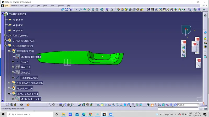
- THE TOOLING axis was decided along z direction considering it selection rules menctioned above
- next we create an axis system along a suitable point according to the boundary and designe of the component ensuring the rules of selection tooling axis direction are not voileted
- here we have an un coised pocket which has to be cleared along the tooling direction
- hence we create a sketch lines bisecting two opposite faces of the pocket and another sketch line at certain angle to the oe remaining face (say 3 deg)which can be changed accorcing tho the draft analysis report
- bisect the two lines in order to create the tooling axis
DRAFT ANALYSIN OF CLASS A SURFACE
draft analysis is performed on the component in order to check wheather the compoent can be maufacturing or not.This draft analysis tool in catia allows us to analyse the draft provided on the surfaces .We can check whwather they follow industry standards and if now we can modify it accordingly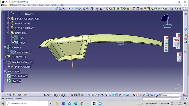
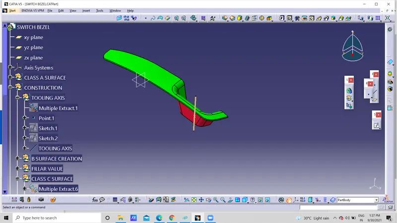
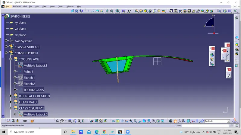
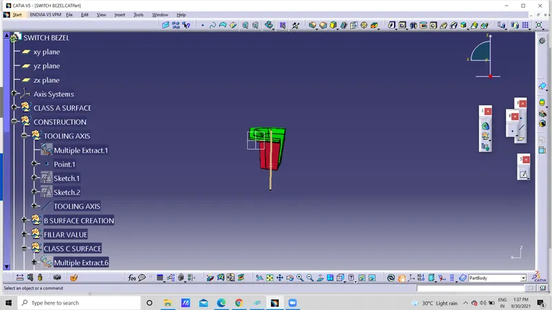
 CONCLUSION: finally successfully construct the swich bezzel