Week 8 - Challenge 5 - Core & Cavity Design
CORE AND CAVITY DESIGNE
AIM: to create the core and cavity blockes for the switch bazel designed in the earlier challenge .
creation of tooling axis for the given class a surface :
- tooling axis direction is the direction in which the core and cavity open .
- the selection of the tooling direction depends up on the product and the features of the product .
- the tooling direction is selected by visual checking the part and in such a way that there are no additional side cores required for the molding process . this ensure proper clearence of the part after the process
the below are the steps for creating the tooling axis
- create the point at the bottom surface of swutch bazel class a surface and insert an axis system at that point
- for tooling clearence axis in the y direction ,a position sketch is created by inserting the clas a surface with the zy plane
- lines are drawn to represent the phase parallel to the assumed tooling direction
- then the two lines are bisected ,resulting in the tooling clearance axis in the y direction
- then the two lines are bisected , resulting in the tooling clearence axis in the y direction
- similarly for x direction ,a positiond is created by intersecting the class a surface with the zx plane .
- lines are drawn to reprenent the faces parllel to the assumed tooling direction
- since we donot have an opposite face we cannot bisect the lines to create a tooling axis , we create a line based on the required draft angle with the parallel face
- the line represents in the tooling clearance in x direction.
- publish the tooling axis and the class a sutrface for easy axis for working with them i the feature
cavity :hallow half half of the mold typically refered as the a side
core: half of the mold that fill the hallow side typically reference as the b side
parting line: line formed in the model part wher two halves of the mold meet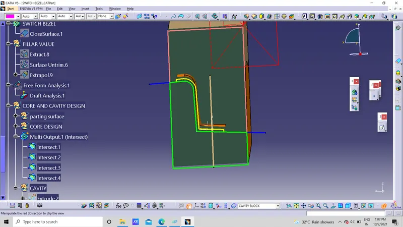
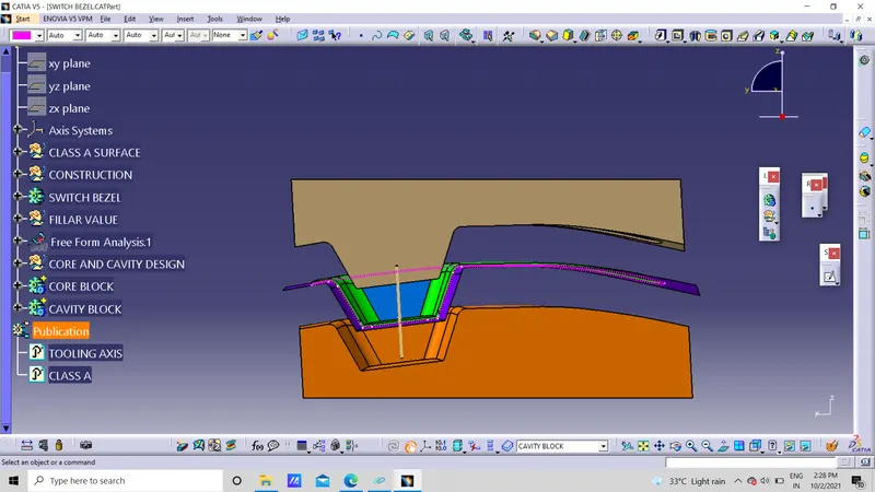 happ
happ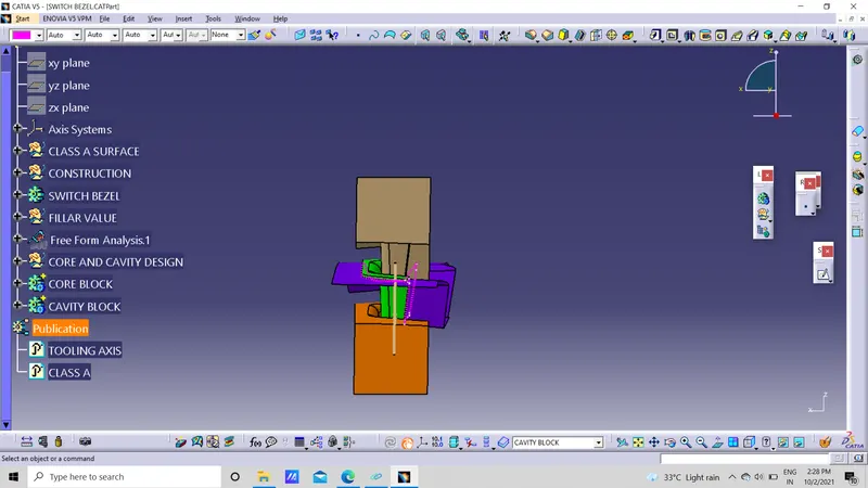
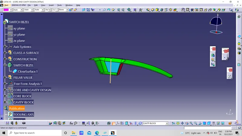
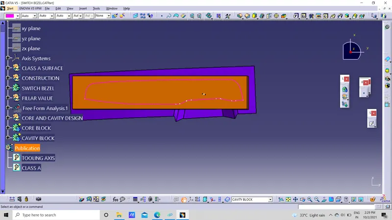
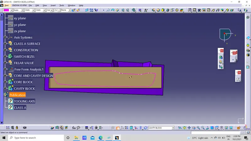 conclusion :finally happend a core and cavity design