Week 9 - Project - Master Section Development
MASTER SECTION DEVELOPMENT OF B PILLAR
Input: The Class A Surface of B-Pillar and its Master Section is obtained as an input from senior engineer, who observes the features of class A, attained from the studio and generates an cross sectional referance sketch with respect to the obtained Class A Surface. It is important to note that the skill for creating the Master Section can only be attained with some years of experience, since the designer must have the capacity to have a practical imagination in creating the necessary thickness and fixatations as per the necessary requirements.
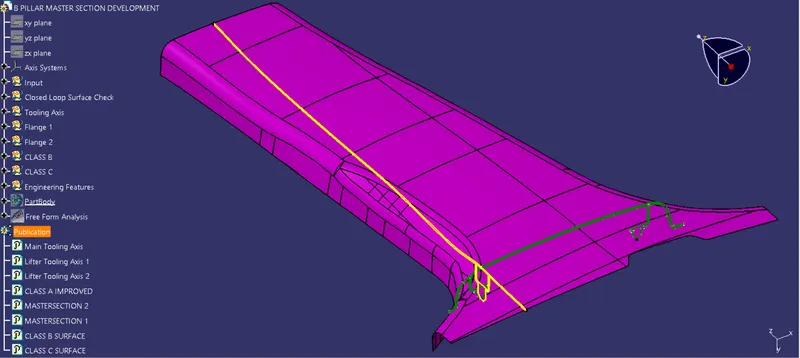
A Surface and Master Sections
Curvature Continuity Check: It is always important to inspect the nature of the class A surface before converting it into a part body. The surface which is to be converted into part body should have a proper boundary, as per the Class A Surface of B pillar, it must have a single closed loop boundary and its condition is satisfied over here. If the Class A Surface is not proper, then surface imperfections must be rectified first before proceeding into the part modeling processes.
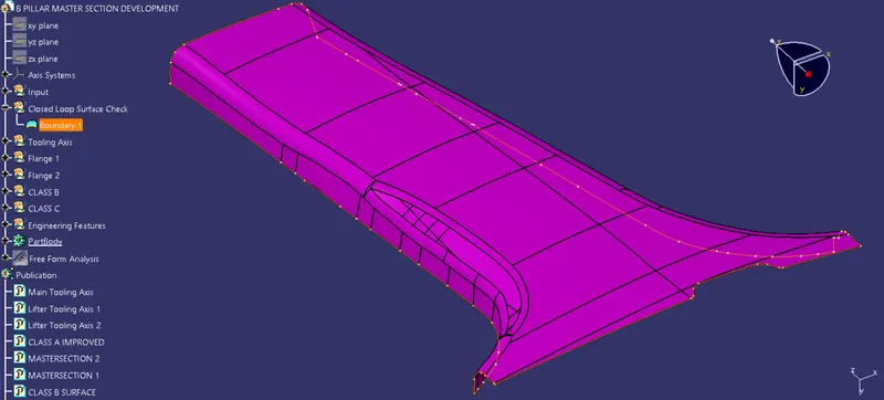
Curvature Continuity Check
Surface Draft Analysis: The surface of the B-Pillar is imposed to draft analysis. The tooling axis is created normal to the surface of B Pillar along Y-axis. The main tooling axis geometry created over here is iso-constrained. It is observed that the draft angle of three degree is deviating towards the ends of two edges. Negliting the deviations by assuming the A surface approval as expert decision, the modeling processes is further executed.
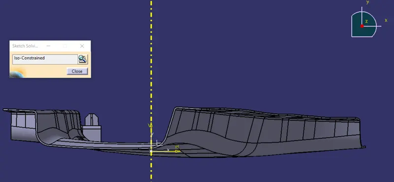
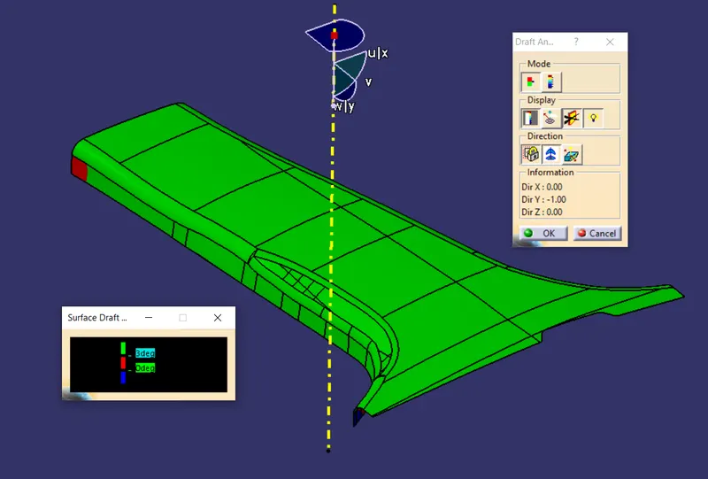
Tooling Axis Geometry and Surface Draft Analysis
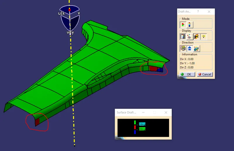
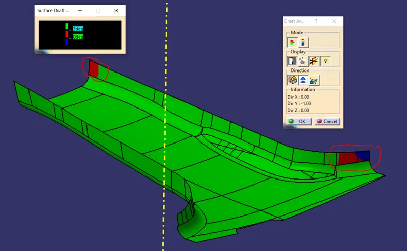
A Surface Errors
Engineering Feature Development: Flanges, Dog House, Screw Boss, 2-way locator, 4-way locator, ribs etc, are considered to be the features in automotive trim's plastic product development. All these engineering features are developed with the aid of master section's under the guidence of senior engineers.
Flanges: The flanges are extensions created in part body for part orientations and attachments. The flanges are created for both A and B surfaces. Usually the flanges are features which holds the surface area of features together.
Closed Volume Part Convertion: The A and B surfaces are left as a referance to form C surfaces with the necessary draft angle. It is always important to note that the draft inclenation must not be towards the A surface, since the flash formed over the edges will affect the quality of the surface. The finally created closed volume surface is inspected for surface imperfections and the part is formed by closed volume option.
Dog House and Locator's: The maximum draft angle for dog house is 1.5 degree. With the referance to the master section the draft angle of 0.5 degree is set for both dog house and locator. The thickness of the dog house wall is reduced to 1mm for a height of 4mm, having its actual thickness as 2mm approx as per the referance of master section. An draft of 0.5 degree is also provided along the lifter tooling axis on the internal dog house surface and along the main tooling axis for the ribs.
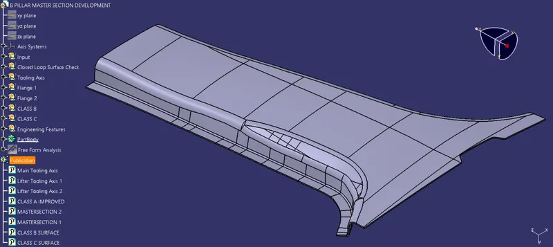
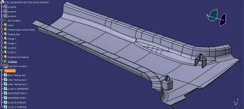
Part Body of B Pillar
Ribs: The ribs are engineering features that are provided on the plastic trim components to act as a support and enhance the strength or acting as a strengthining feature to the part. Here the ribs are designed with referance to rib root diameter, since there is a need for uneven wall thickness. As suggested in the design rule, 40% of the rib thickness may vary depending upon the resin used and 5X approx height can be of lesser then and equal io it. These suggestions are taken under consideration with an intermediate rib spacing of 50mm and draft angle of 0.5 degree towards the main tooling axis. As per the design rule the rib root diameter must not exceed more then 30% of its actual thickness. Here the wall thickness of the trim component is 2mm by 30% increase it will be 2.6mm. But the rib root diameter's observed over here is 2.384 and 2.335 respectively which is less then 2.6mm. Therefore the design rule is satisfied and the part modeling is done sucessfully.
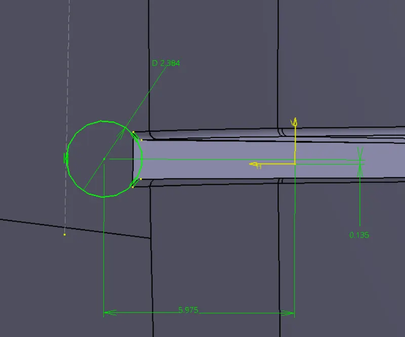
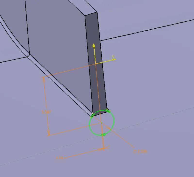
Rib Root Diameter
Part Draft Analysis: The part draft analysis is done along two different axis. Which are said to be Main tooling axis and lifter tooling axis. The draft of 0.5 degree is provided to all the engineering features of B surface. A draft of 3 degree is provided to A and C surfaces. An internal draft of 0.5 degree is provided to the internal area of the dog house along the lifter tooling axis. The errors are found at the edges due to the imperfection's occured in Class A surface and the report is submited to the senior engineer.
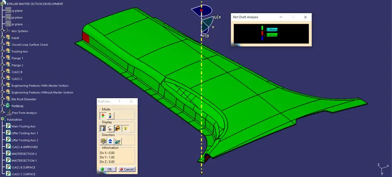
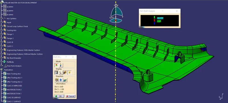
Part Draft Analysis
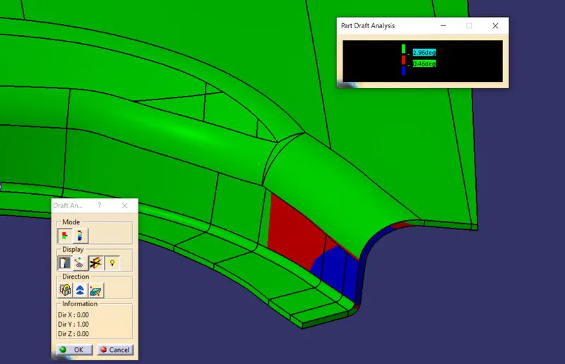
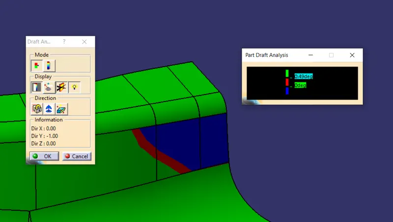
Part Draft Analysis Errors
Lifter Draft Analysis: The Draft Angle is provided on the internal area of the Dog House. It is done for providing a comfortable movement of lifter without damaging the part and to get rid of major surface imperfections at the internal wall of the Dog House.
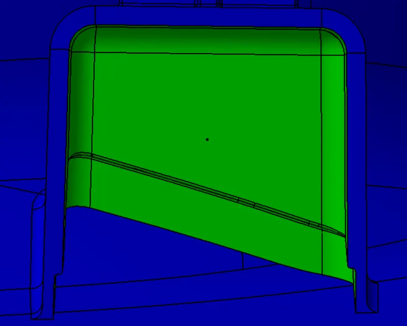
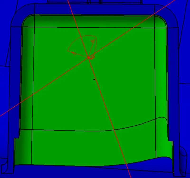
Dog House Draft Analysis
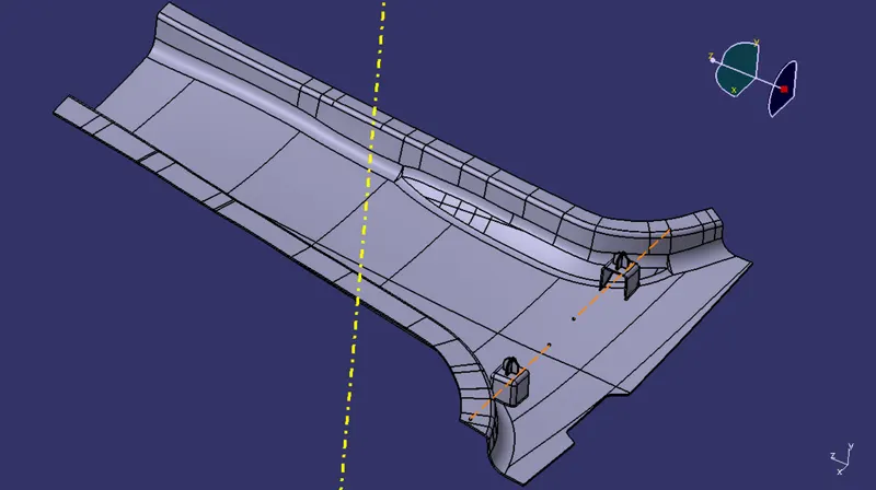
Main and Lifter Tooling Axises
Tree Diagram and Publication: It is always necessary to present the part model in a readable manner. For understanding the sequience of processes which are execuited, the geometrical sets are renamed and arranged in a proper sequience as per the process which is execuited. The important results are published inorder to save additional time occurings through search.
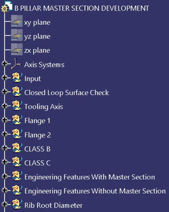
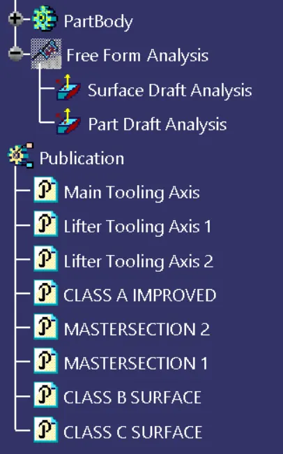
Tree Diagram