Week 8 - Challenge 3 - Switch Bezel Design
Design Report:
1. Initially the Class-A Surface which is obtined as a input from stedio is checked for curvature continuity by boundary and dissambly commands.
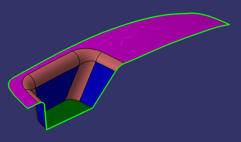
Curvature Continuity Check
2. The tooling axis is creates by bisecting method, having a point and an cordinate system as a basic referance for creating tooling axis.
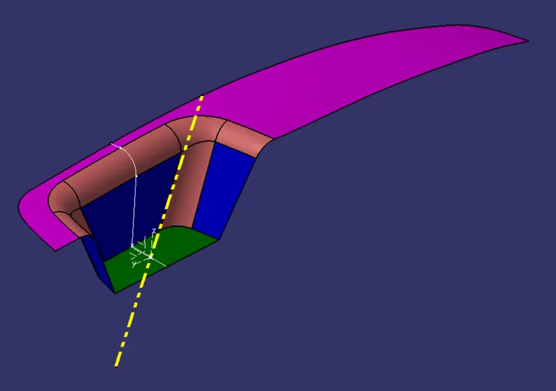
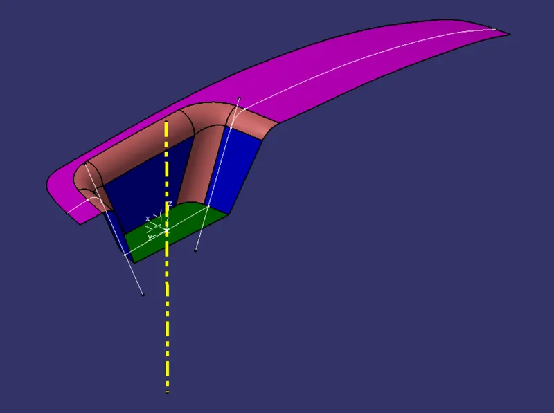
Tooling Clearing XZ&YZ-Axis
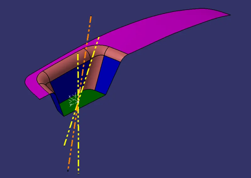
Main Tooling Axis
3. Draft analysis is done for the obtained Class-A surface, inorder to satisfy the necessary design requirement.
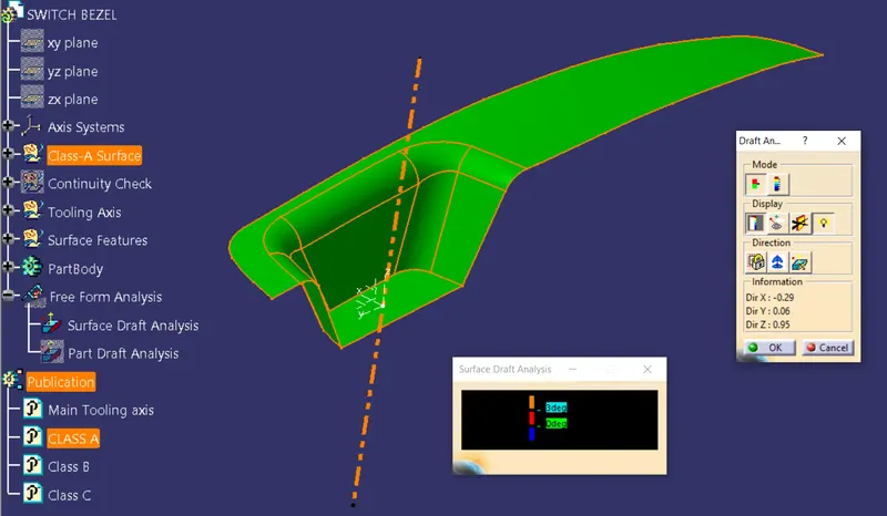
Surface Draft Analysis
4. Class-B and Class-C surfaces are created, with required draft angle(3 degree or 3 degree and above), radius(12.5mm) and offset distance(2.5mm).
5. The trimed closed loop surface model is converted into part model and draft analysis is again conducted to check the design for manufacturing.
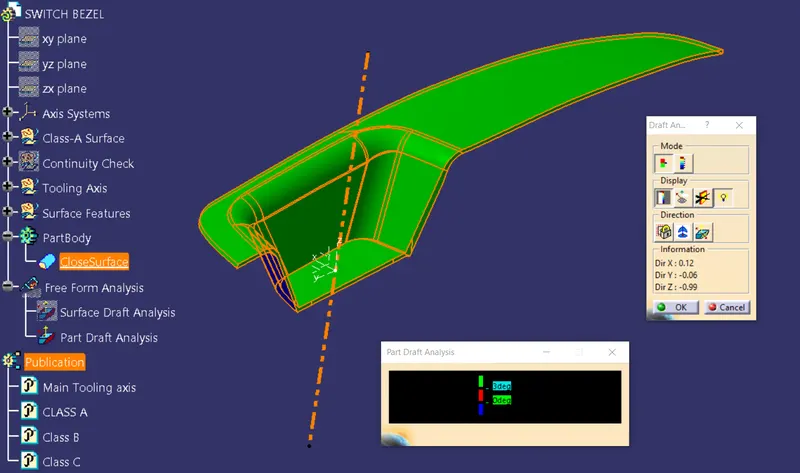
Part Draft Analysis
6. The result obtained from the draft analysis of both surface and part model shows that the model created satisfys the design parameters.
7. The design tree is arranged sequientely and the main tolling axis with Class A,B,C are published.
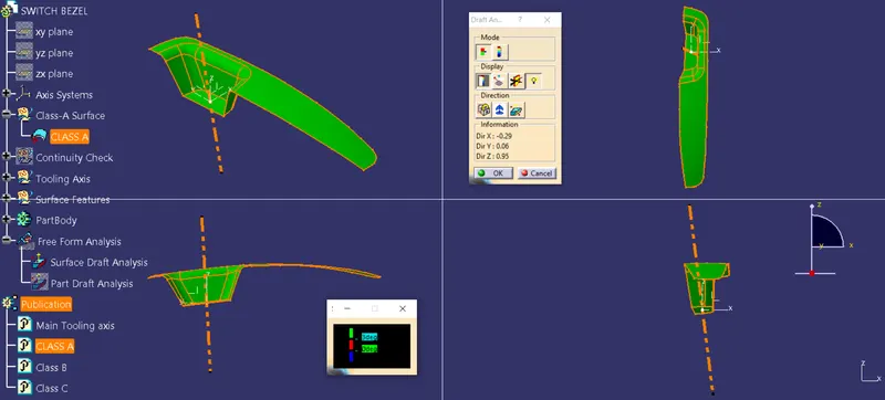
Front, Top, Side and Isometric view of Surface Draft Analysis
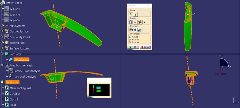
Front, Top, Side and Isometric view of Part Draft Analysis