Week 8 - Challenge 2 - Base Bracket Design
Report on Part Model and Draft Analysis:
1. Surface continuity check with join, disassembly and boundary surface commands.
2. Identifying the prefered tooling direction for making the mold set up.
3. Create the dummy tooling axis. The dummy tooling axis helps us to have a note on directional positioning of the part with respect to entire automobile assembly
4. Identify the parallel surfaces which acts as an intraction between the part to be manufactures and the core, cavity plate. For smooth ejection with minimal friction and force after molding.
5. Create an intersection sketch inorder to make an proper alignment on tooling axis orientation by creating the bisecting sketches.
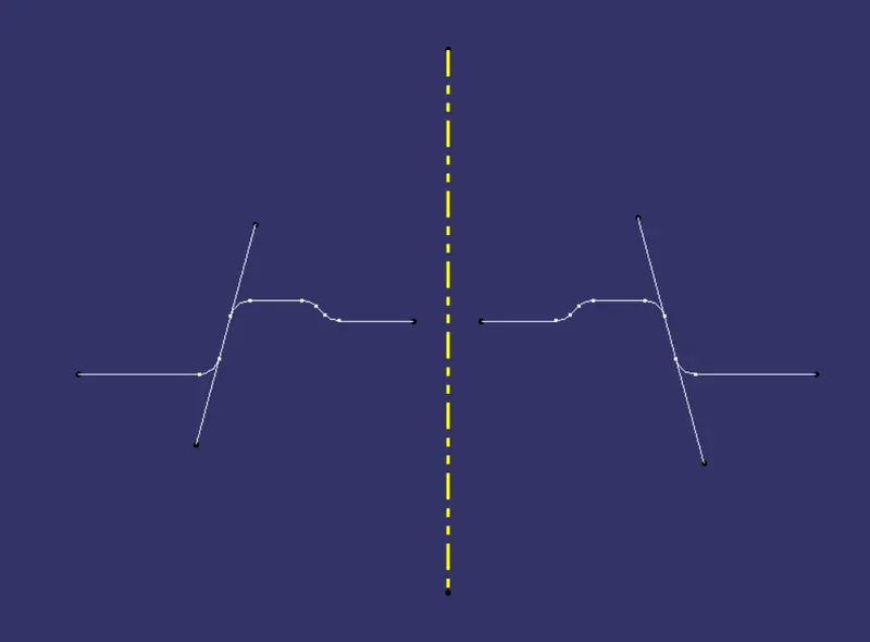
Main Tooling Axis
6. The draft analysis is created inorder to design the part properly, which could be suitable for manufacturing. If proper draft is not provided then the molded part could be hard to ejaculate or could be ejaculated with damage.
7. In draft analysis red is nutral draft (0 to 0.5 degree), blue is negative draft (negative degree's), and green is positive draft (0.5 to 3 degrees and above).
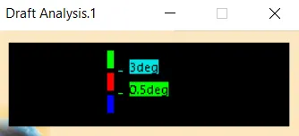
Colour Codes
8. The required draft is considered to be between 0.5 to 3 degrees, but the negative and nutral drafts are used in circumstances which could not be avoided for manufacturing. 3 degree and above is the maximum prefered draft. 0.5 degree is the least draft which is used mostely in critical situations.
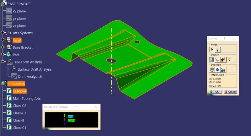
Surface Draft Analysis
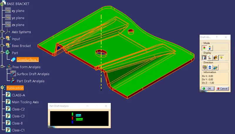
Part Draft Analysis
9. Based on the type of draft and angular orientation, the manufacturability of the part is desided. If the part is not manufacturable the changes are made in the model inorder to make the part manufacturable.
10. Incase if there is a need for negative and nutral drafts then aditional mold set up requirements like lifters has to be used, which may increase the cost of manufacturing and production.
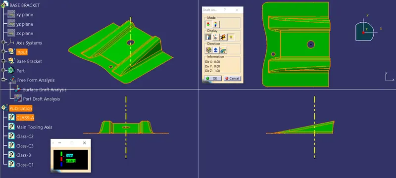
Front, Top, Side and Isometric view of Surface Draft Analysis
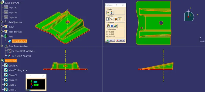
Front, Top, Side and Isometric view of Part Draft Analysis