Week 8 - Challenge 4 - Coin Holder Design
DESIGN REPORT:
1. Class A Surface:
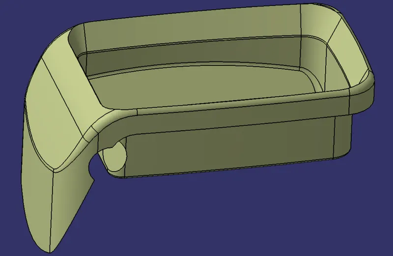
The Class A is a styling surface, which is done in automotive studios. Class A is mainly focused on creative activitys and the Class A also works on customer feed back inorder to promote the product to the grater level of marketing. The obtained surface model from the studio shows that the styling surface needs changes since the obtained styling surface is hard for manufacturing and production.
Class A Surface
By visual observation and measurement of overall dimentions, it can be observed that the surface model do not have enough draft on all sides. The model has an undercut which requies some presise sliding requirements.
2. CURVATURE CONTINUITY CHECK:
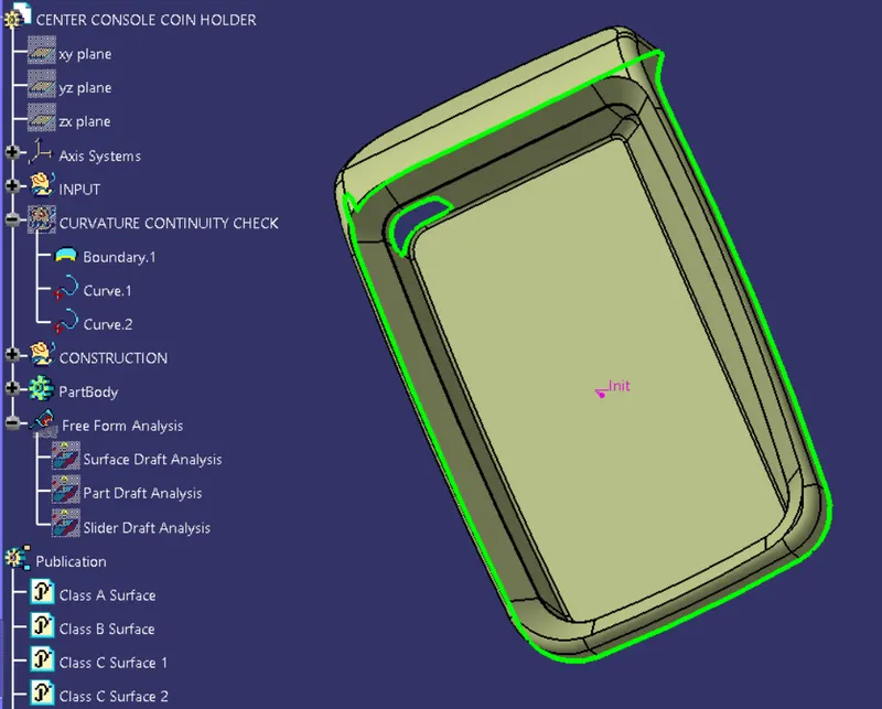
The results on visual observation shows the surface model is not easy to manufacture. Inorder to make an confermation the surface model is subjected to curvature continuity and draft analysis. The curvarure continuity check is done by setting the boundary curves and disassembling the domine curves.
Curvature Continuity Check
It can be observed that the boundary has two different closed loops. So only two domine curves are possible. If there are more then two domine curves then the Class A surface is to be reconsidered properly.
3. SURFACE DRAFT ANALYSIS:
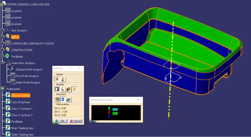
The surface draft analysis is done before conducting complete part analysis. The surface draft analysis is considered to play a major role in finding the posibilities for DFM even before starting the trim works. The colour codes will clearly say the quality of the surface design.
Surface Draft Analysis
Initally while measuring the overall dimentions, surface to surface dimentional measurement was made possible over here, which shows that there is no draft given on the surface and it is clearly proven here from draft analysis. The blue colour code at both internal and exernal surface proves that there is no draft given at the internal walls of the surface model.
4. PURPOSE OF DRAFT ANALYSIS:
The draft is mainly given to avoid the frictional intraction at the intersection between the mating parts. The losses due to friction will cause wear, tear and drag marks an the parts to be manufactured. Tool life will decrease. Production cycle time will increase. Assuming that the customer do not care about the losses due to "no draft", the working processes is continued further.
5. GEOMETRICAL SETS AND SURFACE TRIMS:
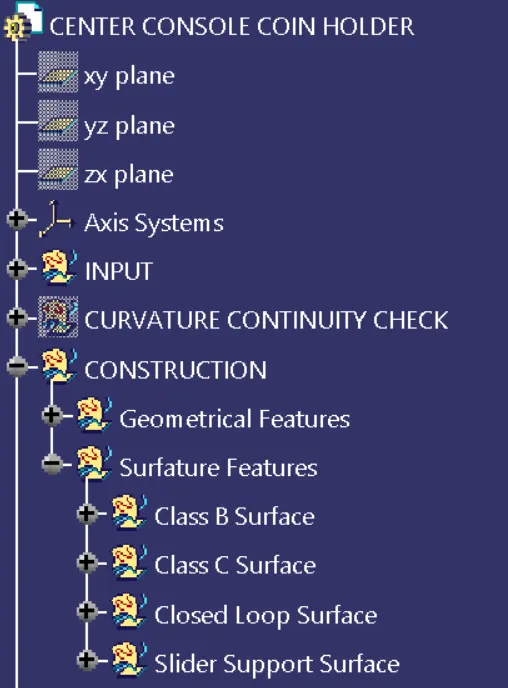
It is always the responsibility of a designer to execute his work in a regular sequence. The purpose of the geometrical sets is to catogrise the trim features into different segments so that the future proceeding could be executed properly. In geometrical sets we can split the sketces and surfaces into different groups and work on it. It's a directory to set an flexible user interface.
Geometrical Sets and Surface Trims
The trim works are done segrigating the surfaces into different groups and the working is executed segment by segment with proper geometrical sets, leaving the completed closed loop trimed model at last.
6. RADIUS, JOIN AND PART BODY:
Based on the Class A surface, the Class B surface radius is calculated by intrecting and measure tool. All the aurfaces are joined at a minimal tolerance of 0.001 tolerance and the obtained closed loop surface is converted into part body.
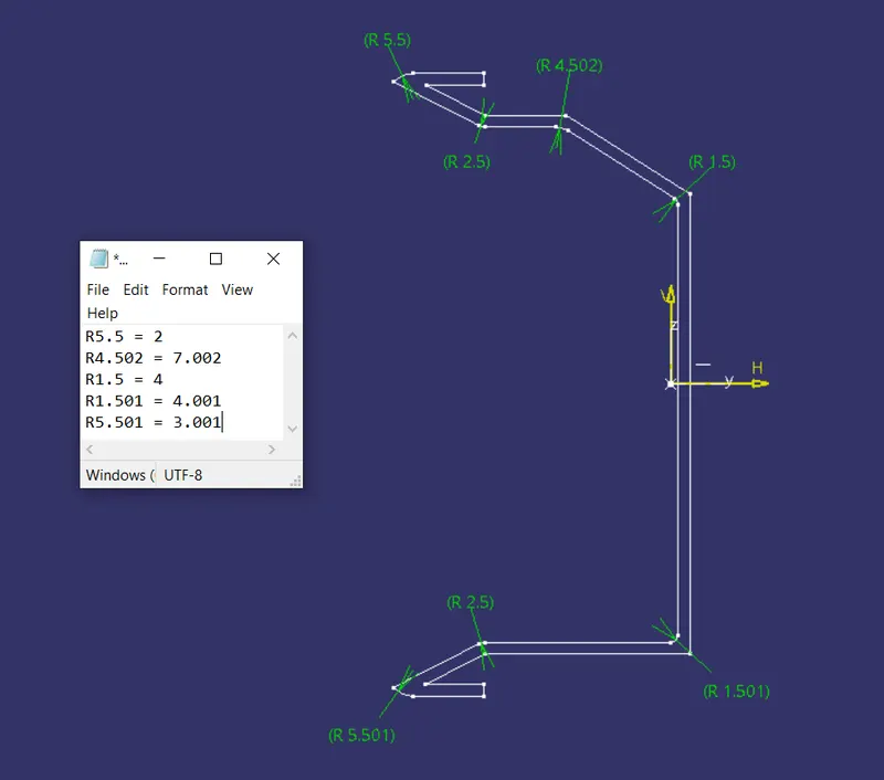
Internal and External Radius
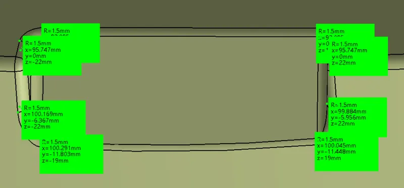
Internal and External Radius on Internal Draft
7. PART AND SLIDER DRAFT ANALYSIS:
The Part draft analysis is created by bisecting method, where the tooling is cleared along XY and YZ axis plane. The bisecting line of XY and YZ axis is made as Main tooling axis. The Slider tooling axis is created by extracting a plane at its face, creating a point at the circular centre edge and the axis is made by point and direction method. The result obtained by part and slider draft analysis shows that the design is not feasible for manufacturing and further changes must be done in Class A surface inorder to obtain a proper design with respect to manufacturing.
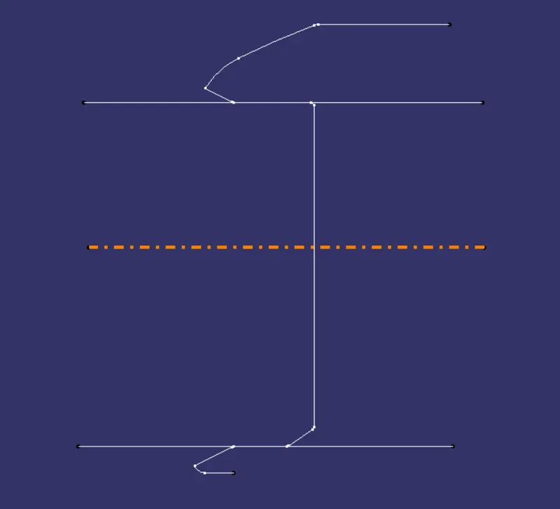
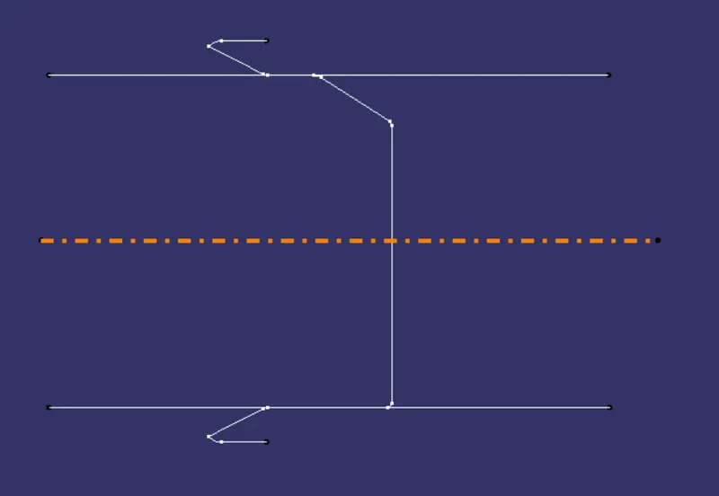
Tooling Clearing Along - XY and YZ Plane
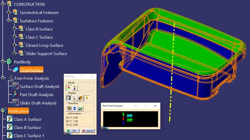
Part Draft Analysis
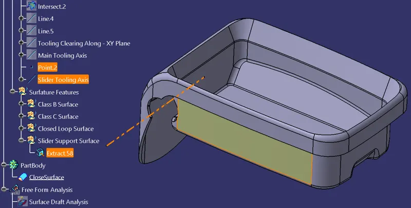
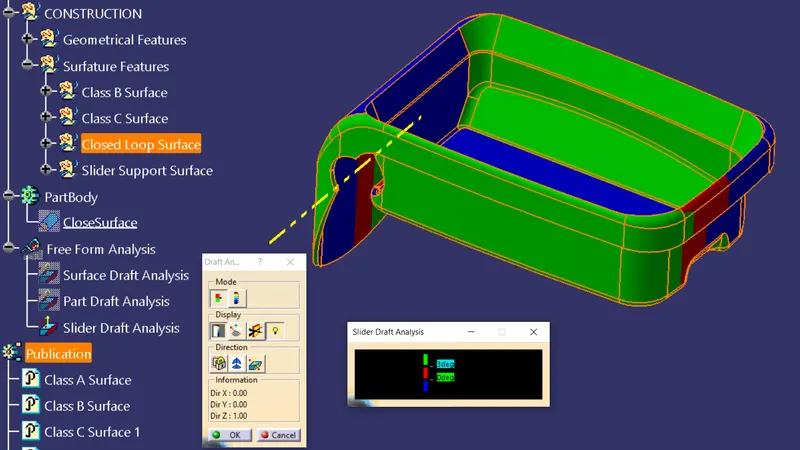
Slider Tooling Axis and Draft Analysis
8. PUBLICATION:
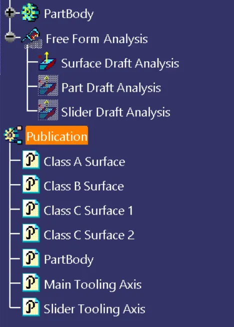
Inorder to view the results obtained by draft analysis easily, the surface based features, part body and tooling axises are published. It helps us to visualize the results quickly instead of searching for the options everywhere.
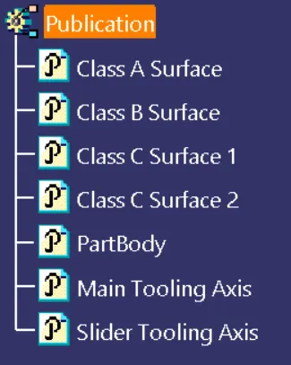
Publication
9. MULTIPLE VIEW ORIENTATIONS:
The view orientations helps to know "how the product is?" and "what are all the analysis to be conducted?" inorder to optimize the design in a better manner. Adopting all DFM and DFA parameters.
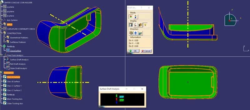
Front, Top, Side and Isometric view of Surface Draft Analysis
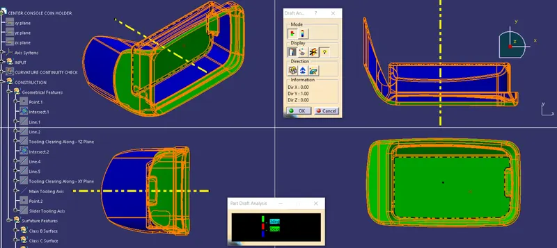
Front, Top, Side and Isometric view of Part Draft Analysis
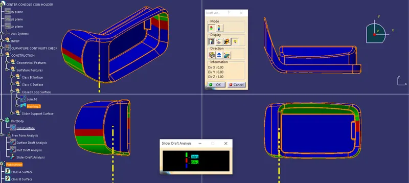
Front, Top, Side and Isometric view of Slider Draft Analysis