Week 9 - Project - Master Section Development
AIM
To create B pillar of a Car using the Master section and Class A surface as input and performing Draft analysis
Performed Activities:
Created improvement of Class A Surface using master section
Created B Class Surface
Created C class Surface
Performed Draft Analysis on A Surface, solid part of the Body and added on Engineering Features
Created Dog House, Locator Pins, and Ribs as Engineering Features on design guidelines
Procedure
TOOLING AXIS
Import the Class A surface model of B Pillar and check the Boundaries
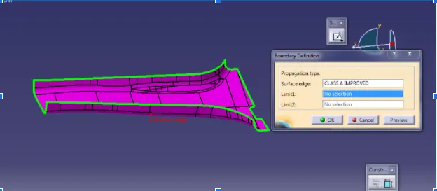
Checking the Boundaries ensures whether gaps and patches are available in the model
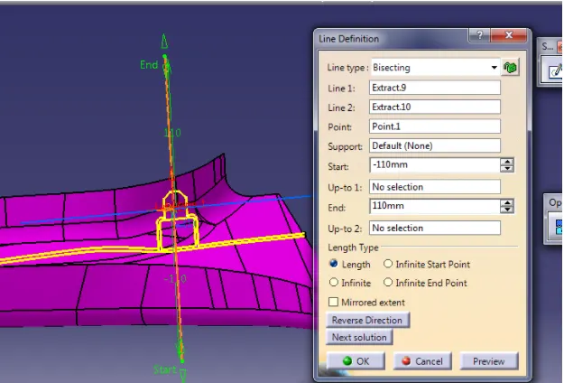
A Tooling Axis needs to be created in a direction from which it can capture most features of the product
Generally, A tooling axis will be created perpendicular to the base surface of the support
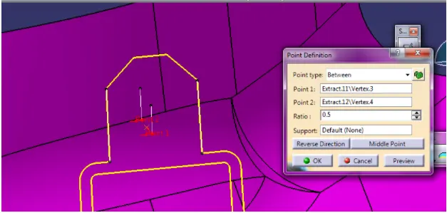
A reference point can be based on the Master section given as an input
Create a point using the point in-between option and select the two points at the end of the Dog House of the master section
Now using the line definition tool create a line passing through the point which remains the tooling axis
DRAFT ANALYSIS ON CLASS A SURFACE
TO PERFORM DRAFT ANALYSIS ON CLASS A SURFACE INITIATE WITH THE DRAFT ANALYSIS
TO GIVE DRAFT DIRECTION SELECT THE COMPASS AND ALIGN IT ON THE TOOLING DIRECTION
ONCE AFTER THE ALIGNMENT SELECT THE CLASS-A SURFACE AND SELECT
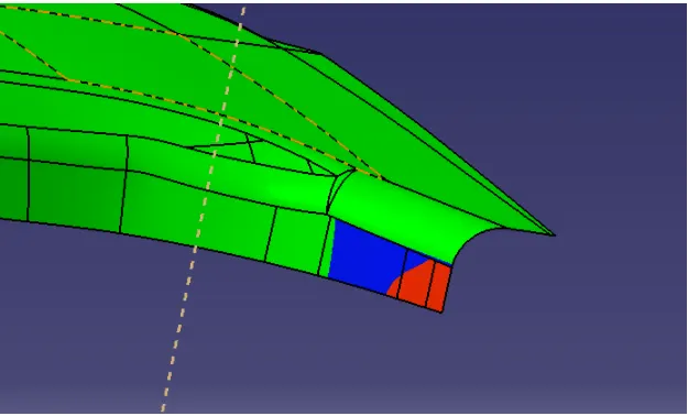
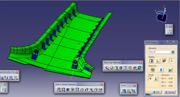
THE SURFACE OF THE MODEL WILL SHOW US THE DRAFT ANGLE
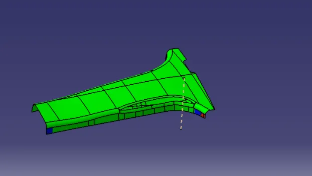
GREEN COLOUR = 3 DEGREE AND MORE THAN 3 OF DRAFT ANGLE
BLUE COLOUR = DRAFT ANGLE BETWEEN 0 TO 3 DEGREE
RED COLOUR = DRAFT VALUE IS NEGATIVE OBJECT FAILS
A small portion of the Class A surface is getting the negative degree of the draft analysis result. As of now, we are ignoring it
CREATING FLANGES ON A SURFACE
On referring to the master section it has been concluded that there are some flanges which are on the edges of the CLASS A surface
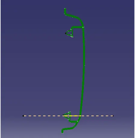
By extracting the edges of the class and sweep those edges at a specific degree
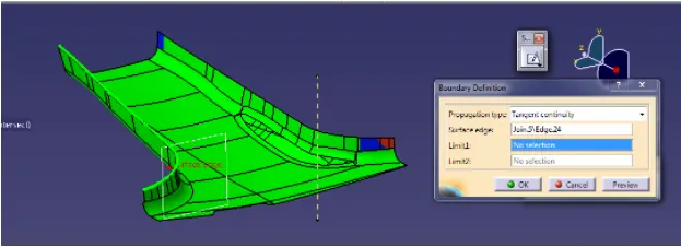
By Extracting the surface of side walls we can sweep by the surface
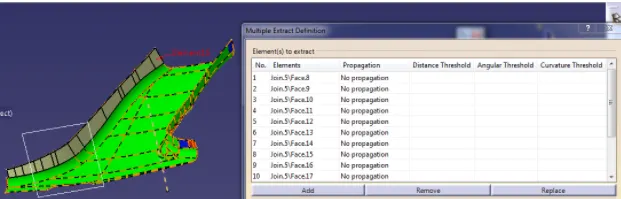
Following this performing the sweep operation on based outwards of draft angle which matches the master section line
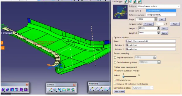
This operation is followed on both side of the walls it has been referred as Flange 1 and Flange 2
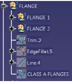
CLASS B SURFACE:
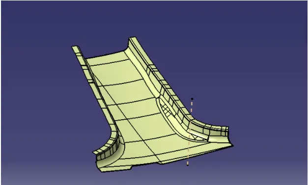
To create the Class B we are the Class A surface which has been created with flanges and making offset operation for 2mm to get the exact surface A
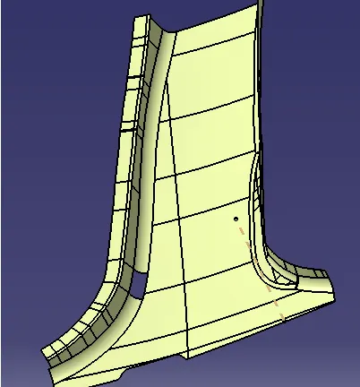
As the thickness of the component has been concluded as 2mm based on the master section given
While making offset of the surface we got some patches that are missing we are going to use the multisection solid method and gonna rectify the patches
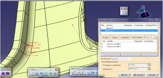
As the patches have been cleared working on the flanges and creating as a single body CLASS B
CREATING C SURFACE
To make C CLASS Surface we are going to extract the sidewalls of the flange and sweep along the tooling axis
When extracting the sidewalls of the flange we face some connecting issues so we are trying with the curve smooth option which smooth the curve and replace the extract with the smooth option which helps to get the sweep surface better
As the complete surface cannot be a sweep in an exact body as it has complex curves so it has been created as a separate section of sweep
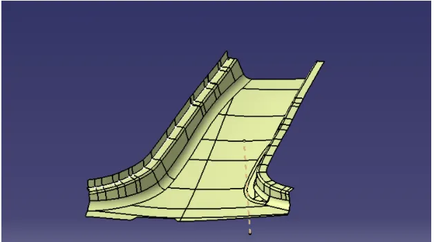
The sweep has been made either walls of the flange along with the tooling axis
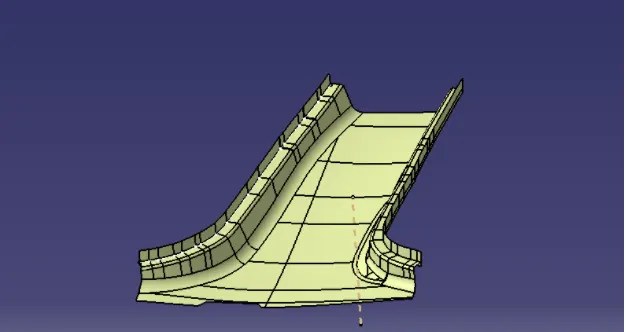
The bottom wall also subjected to sweep along the tooling axis
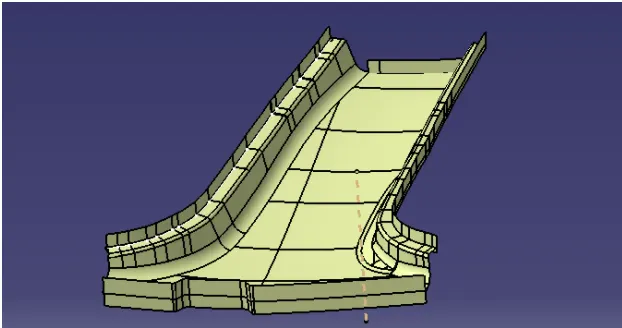
The sidewalls cannot be sweep as because of the complexity so we are trying a different method connecting flat surface with the multisection solid option
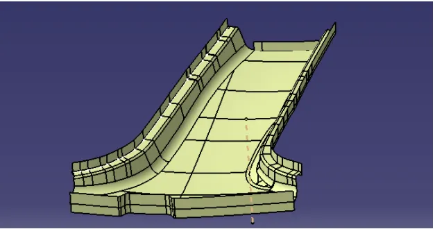
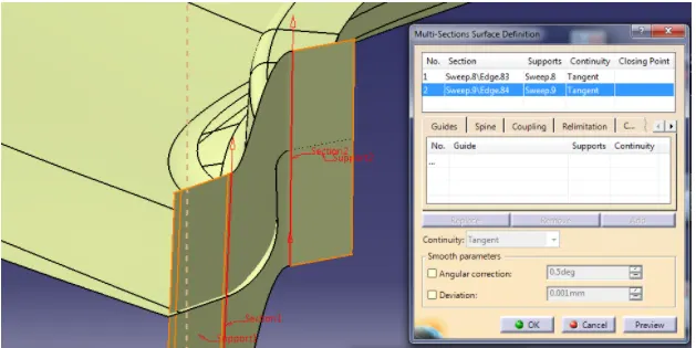
Once after the creation of all the walls, those are subjected to trim operation to make it as a single c surface
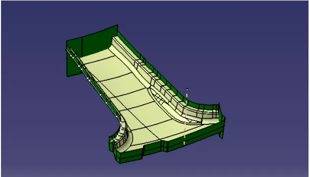
Once after the creation of CLASS A, B, C surface we are performing the trim operation between these three surfaces to make it a single closed body
As some regions haven’t met the requirements of trim we are extrapolating those surfaces and performing the trimming operations
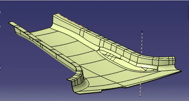
Now this closed surface has been converted as a part body by following the closed surface command
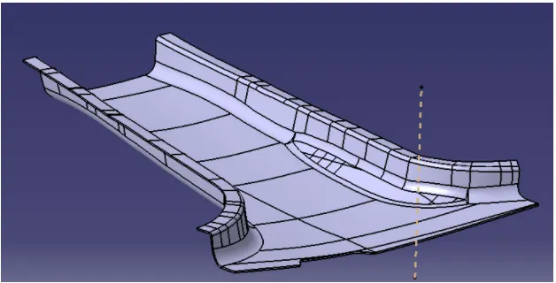
ENGINEERING FEATURES:
DOG HOUSE:
The dog house is an engineering feature that is used in plastic design to support other engineering features like screw bosses, push pin clips, snap fits, locator pins
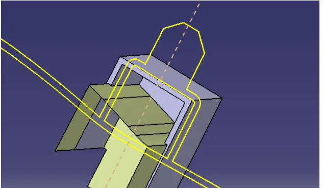
To create Dog house master section has given as input on following the master section. The top surface and support walls of the dog house on which the locator is laid is created by simply extracting the lines from the master section in a sketch and extruding them to a certain length
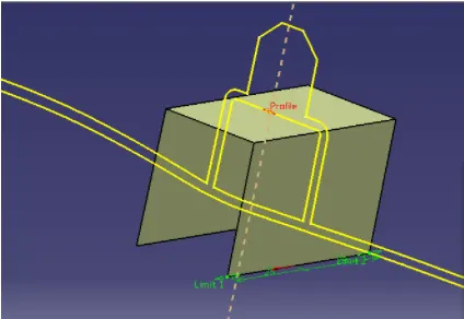
Now we are going to perform trim operations according to the master section 2
The wall closing the dog house is created and another wall is created at the open end of the dog house to split it with a solid body
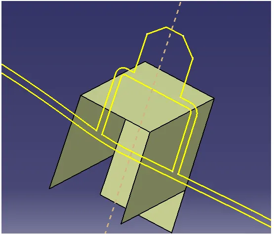
Perform a closed surface on the part design and make it a solid
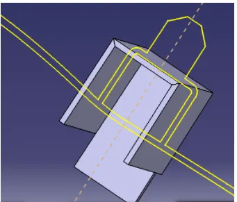
The inner walls of the dog house are created at an offset value of 1.2mm maintaining the 40% design rule from the outer walls and the top surface for the inner walls is created by intersecting the CLASS A surface with the back wall
The surface is then split with the close solid to create the inner walls of the dog house
4 WAY LOCATOR
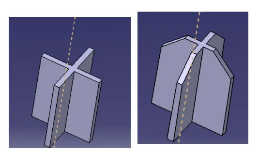
A locator is a gateway to make sure the parts we are putting together fit the way we want them to fit. To create a 4-way locator, we need to create a sketch with two lines perpendicular to each other
A draft of 0.5 deg is given to the locator and also a chamfer of 5mm at 45 angles is given to the top edges of the locator
RIBS
Ribs are created to strengthen a part without increasing the thickness of the wall
Because less material is required, ribs can be a much more cost-effective solution as well
We create multi ribs which are 50mm apart first go to the class A/B surface. Now copy the solid body of Rib which we created and paste it in the main tree structure Use the translate option the copied solid body of the rib can be moved from one point to other points
Offset class B surface to 10 mm and trim the ribs with it removing the excess point and give a draft 0.3 to the ribs
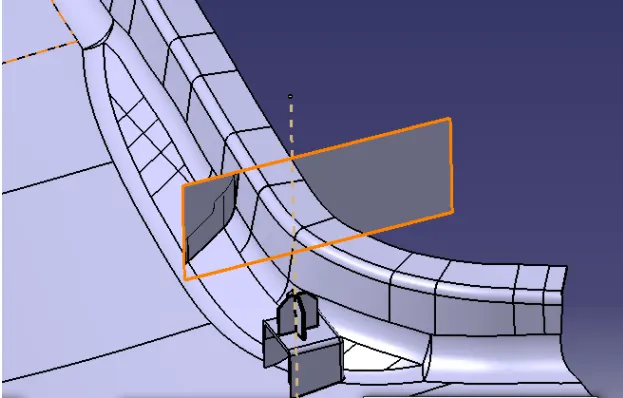
Once all the engineering features are created, add/ trim them with the main body
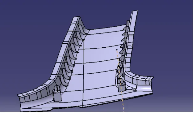
B Pillar and give appropriate fillet value to all the parts of the body
DRAFT ANALYSIS OF FINAL MODEL
TO PERFORM DRAFT ANALYSIS ON CLASS A SURFACE INITIATE WITH THE DRAFT ANALYSIS
TO GIVE DRAFT DIRECTION SELECT THE COMPASS AND ALIGN IT ON THE TOOLING DIRECTION
ONCE AFTER THE ALIGNMENT SELECT THE CLASS-A SURFACE AND SELECT
THE SURFACE OF THE MODEL WILL SHOW US THE DRAFT ANGLE
GREEN COLOUR = 3 DEGREE AND MORE THAN 3 OF DRAFT ANGLE
BLUE COLOUR = DRAFT ANGLE BETWEEN 0 TO 3 DEGREE
RED COLOUR = DRAFT VALUE IS NEGATIVE OBJECT FAILS
MAIN TOOLING AXIS
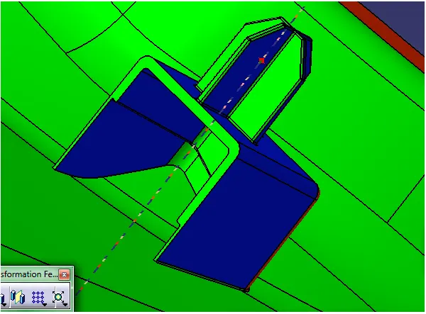
LIFTER TOOLING AXIS
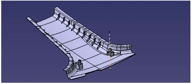
3D MODEL OF B PILLAR
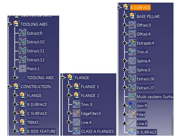
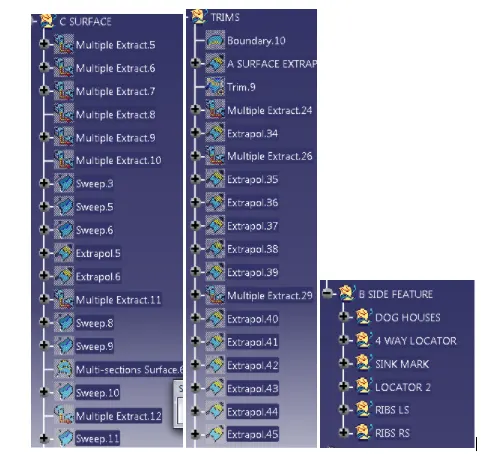
TREE STRUCTURE
CONCLUSION
B PILLAR with Engineering component has been created along with the Draft Analysis