Week 9 - Project - A pillar Design with Master Section
Aim-
Picture of the sketches with Sketch solving status’s geometry tab
Picture of the Detailed tree structure.
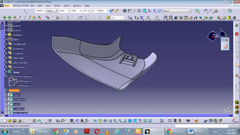
Picture of the 3D CAD
Create a closed body
Create a tooling axis and follow design rules.
Follow the Master section to create a flange
Follow the master section for thickness and to create the Closed volume.
Follow the master section to create Attachment features
INTRODUCTION:
CLASS-A SURFACE:
A surface made by the designer is given as an input to the plastic modeler to work on. It is an aesthetic surface and the outermost surface.
CLASS-B SURFACE:
A surface below a certain thickness from the class-A surface is a class-B surface. This is the surface that contains engineering aspects of a model.
CLASS C SURFACE:
A surface that joins class-A and class-B surfaces is a class-C surface.
TOOLING AXIS-
- It is defined as the direction in which the mold/core and cavity open. Selection of the direction of the tooling axis depends on the ease at which components can be easily ejected.
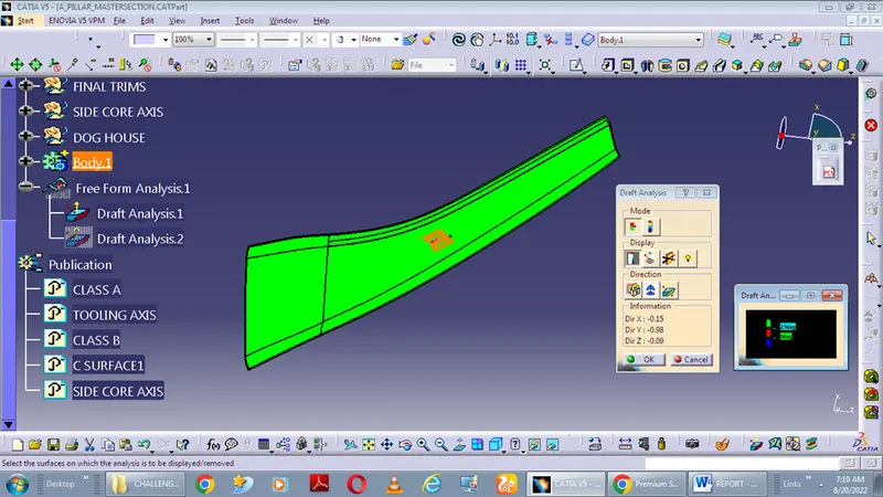
- By analyzing the component the most easily electable direction is somewhere close to the Z direction,(might be inclined to it) so we have made a sketch on the YZ plane of the Axis System) to create a bisecting line considering the 2 faces which might be difficult to be tooled.
Draft Analysis
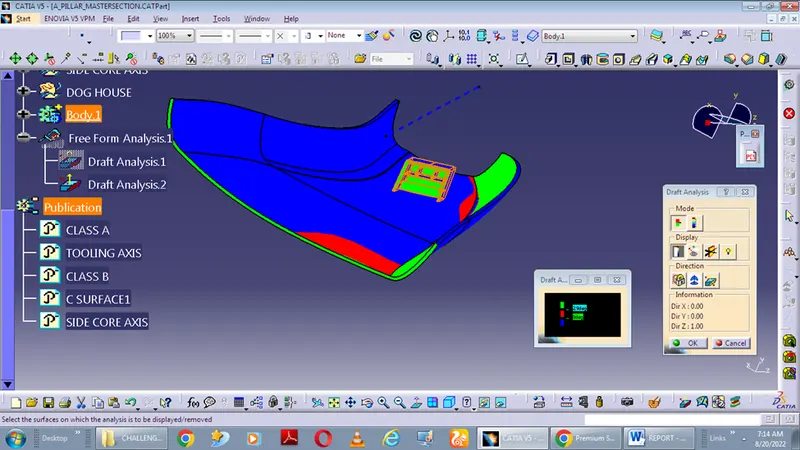
Draft analysis is a method used in design to check whether the component created in CAD is manufactured based on the draft condition applied. The main reason behind the draft analysis is the part manufactured should be easily removed from the mold. It also gives an idea of the draft angle from the tooling direction. Here we are giving a tooling direction in order to eject the component easily from the tool. The ideal draft angle given to automotive industries for plastic components is 3 degrees.
DETAILED TREE STRUCTURE AND CLOSE BODY