Week 9 - Project - A pillar Design with Master Section
NOTE: I have Attached the Report, Photos and CADpart in the Attachment
Week 9 - Project - A pillar Design with Master Section
AIM:
To Create the A pillar Design with Master Section.
OBJECTIVE:
- Ensure using surface command.
- Use closed body command to create the solids
- Rename geometrical set properly.
Output Required in a ppt :
- Picture of the sketches with Sketch solving status’s geometry tab
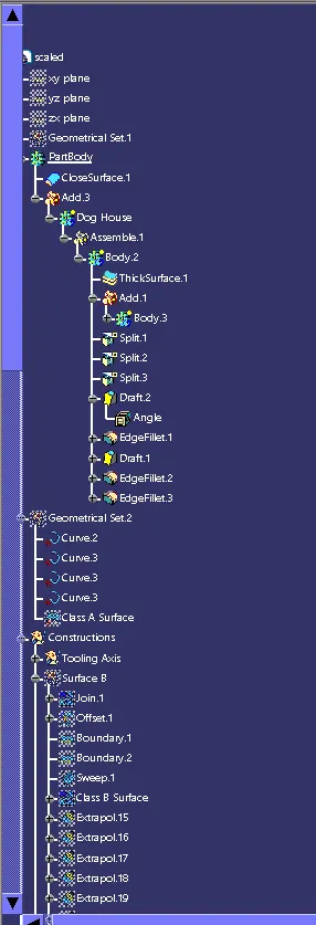
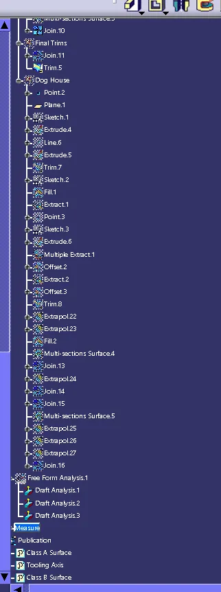
- Picture of the Detailed tree structure.
- Picture of the 3D CAD
- Create closed body
- Create tooling axis and follow design rules.
- Follow the Master section to create flange
- Follow the master section for thickness and to create the Closed volume.
- Follow master section to create Attachment features
- Tke thickness of Plastic to be 2.5 mm
SOFTWARE USED : CATIA
Let us look at how we have designed
INPUT:
CAD DATA is downloaded and Opened with CATIA.
TOOLING AXIS:
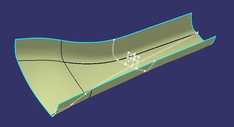
Tooling axis is defined as such all the features of the part can be manufactured easily. so here we followed the below steps to create the tooling axis.
- Two lines are drawn on the master section
- A point is also created
- Both the lines are taken for bisecting and getting the Tooling Axis
- Hence we get the Tooling Axis
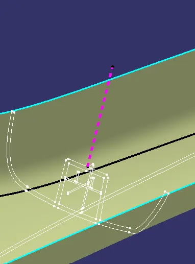
Side Core Axis Also created
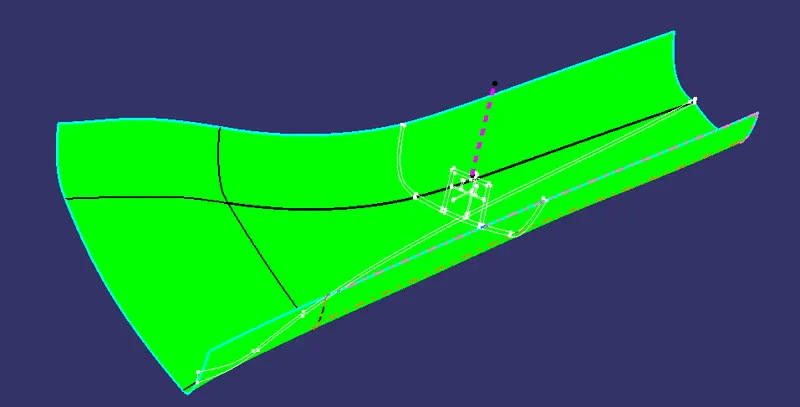
DRAFT ANALYSIS:
- Draft is done on the Class A surface.
- Change it to material in customise view.
- Click the Draft analysis tool and click the surface and align the compass to tooling axis.
- 3 degree is the clearing angle
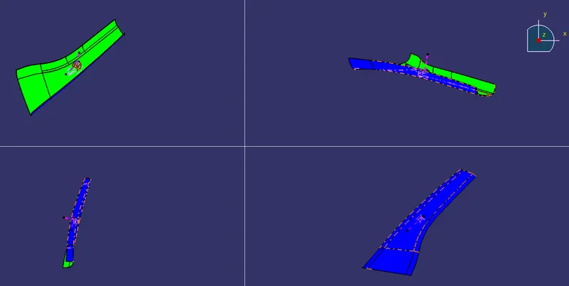
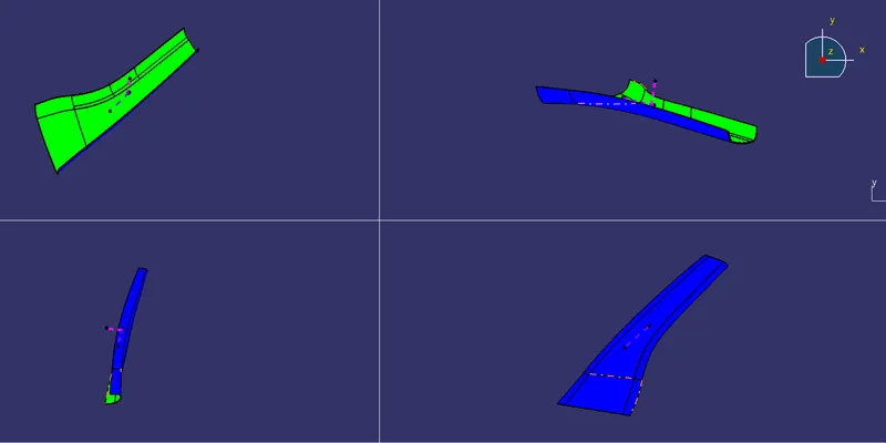
- So here is photo of cleared (Green) draft.
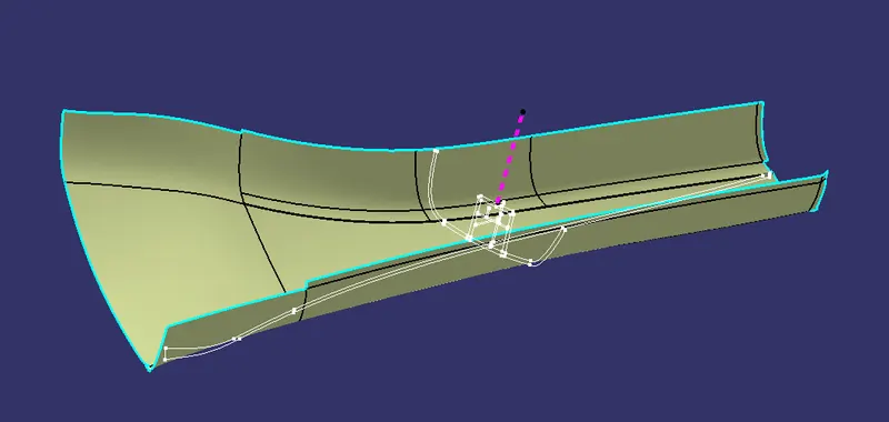
B SURFACE:
- B surface is created by using the given Class A surface.
- Apart complicated face join other faces.
- Offset it to 2.5mm beneath the Class A.
- Create boundry and Create MSS, Extrapolate for the rest of the sections.
- Trim the extrapolates and join if needed.
- Hence we have created the B surface.
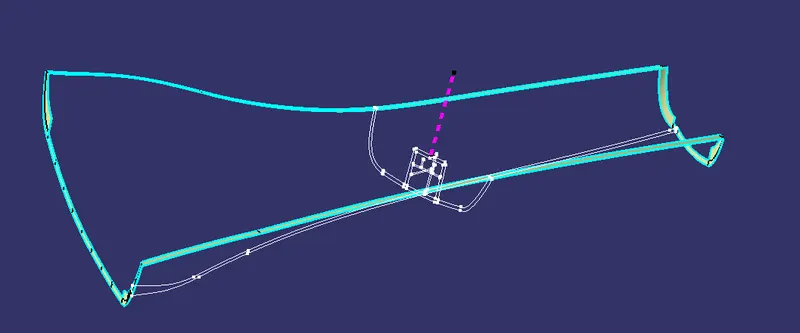
C SURFACE:
- The outer edge of the Class A surface is taken as reference boundry.
- Sweep is made with reference to tooling axis with draft.
- Join the sections and create the C Surface.
FINAL TRIM:
- Join A and C surface.
- Trim with the B surface.
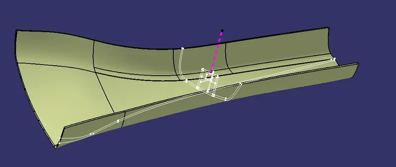
- Closed Body is created
Master Section:
- Master section is used to create the Sketches
- It is then extracted and pad in part design
- Thicken, split are also used
- Reference photo is used to give fillets and holes
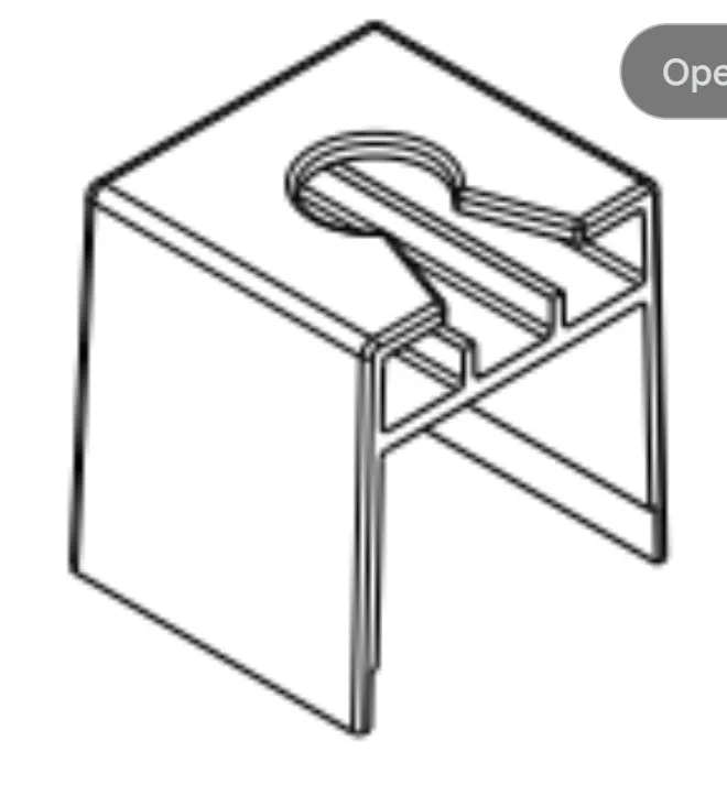
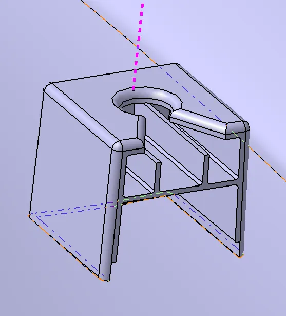
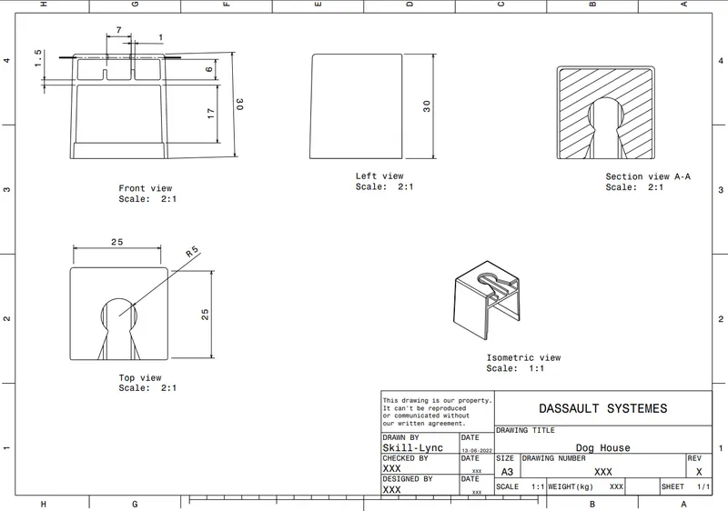
NOTE : Dimensions are different in reference drawing and Master section. But the mentor (rooban) said to follow the master section dimenson and hole diameter as in reference drawing.
DRAFT ANALYSIS:
- Draft is done on the Class A surface.
- Change it to material in customise view.
- Click the Draft analysis tool and click the surface and align the compass to tooling axis.
- 3 degree is the clearing angle
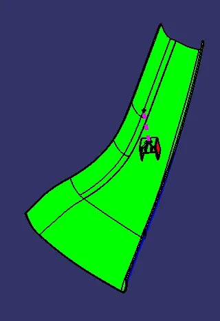
- So here is photo of cleared (Green) draft.
NOTE: Side drafts are not cleared and as discussed with the mentor (rooban) he said that Class A is defective. So Kindly consider
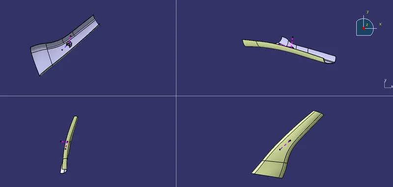
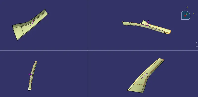
Here are few photos of the model