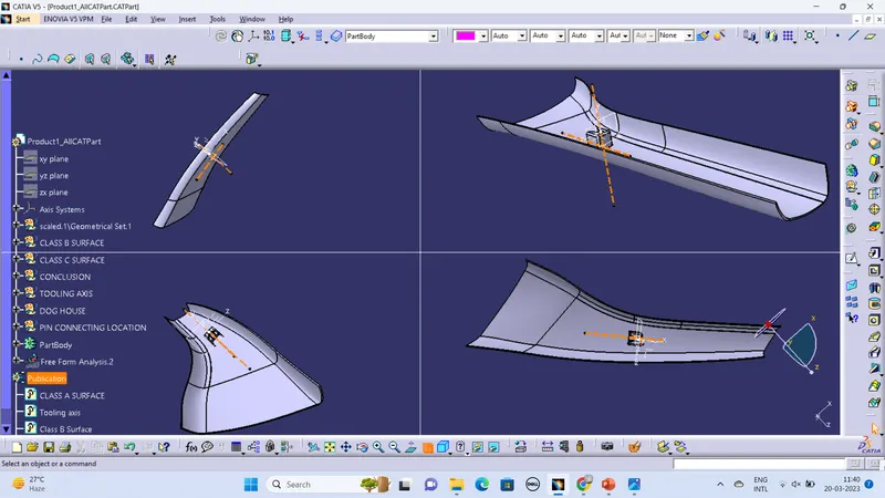
Week 9 - Project - A pillar Design with Master Section
Draft analysis
The draft analysis in CATIA refers to a tool that allows users to determine if they can remove the part that they are designing from the arrangement being used to design it.
How toa do draft analysis in Catia V5?
Step 1:enter part in Catia
Step 2:Click on the insert
Step 3:Click on the analysis
Step 4:click on feature draft analysis
If it says wrong material mode then;
->go to customize view parameters and click on the material mode in shading column
Step 5:click on feature draft analysis
->place the compass on the tooling axis with complete alignment
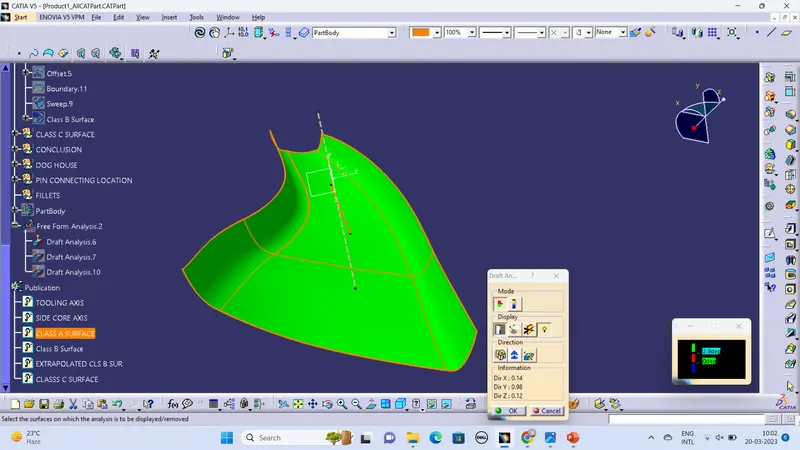
->And click on the surface; if it shows GREEN – OK
if it shows completely blue – Flipbthe direction
***Make use of the mode, display and direction specifications for fruitful draft analysis
Tooling axis
The Tooling axis is the direction in which mold opens when core and cavity opens (or) simply; In molding machine arrangement is given to open the two halves of the mold along a direction which is known as tooling direction..
METHODS TO FIND THE MAIN TOOLING DIRECTION:
There are plenty of methods of approach for creating a tooling axis and they are:
(i)Along axis Direction(X,Y,Z)
(ii)Normal-to-face part/feature/environment part features
(iii)Reference from feature/master section
(iv)Trail and Error by compass
(v)BISECTION METHOD
Among all these methods Bisection method is a more crucial one…
BISECTION METHOD:
Step 1:Select a feasible center to eject an assuming tooling axis and arrange an axis system there
Step 2:click on “intersection tool”; select the supporting plane and surface; We would get the boundary or cross-section over there
Step 3:If possible Do the same operation to create another cross-section with another supporting plane on the axis system then we would get the intersection or cross-section over there too.
Step 4: later on bisect the lines and bisect the overall various reference things to get the exact tooling axis.
Step 5: After identifying the tooling axis;
->Make sure the line Is “published” such that it would be visible in the tree structure out of the geometrical set
->To publish; Go to tools and click on PUBLICATION…
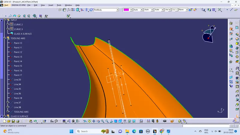
Tooling axis creation using the bisection method by taking some points on curves given in the input and making them isolate such that there would be no issue to master the section
DRAFT ANALYSIS OF CLASS A SURFACE
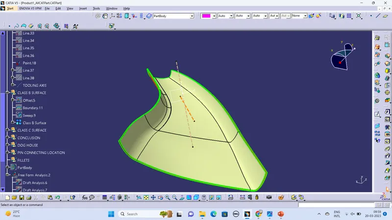
CLASS B SURFACE
CLASS C SURFACE
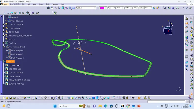
A+B+C SURFACES
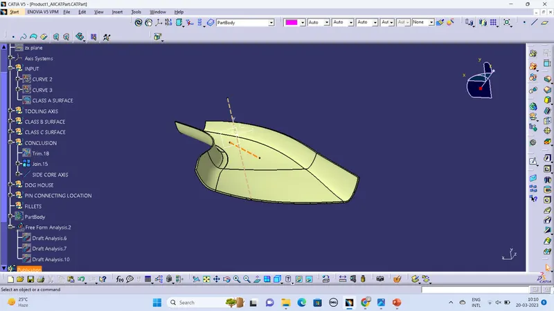
DRAFT ANALYSIS OF CONCLUDED FIGURE
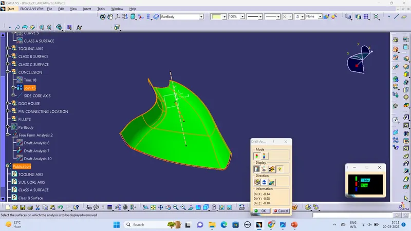
DOG HOUSE AND DRAFT ANALYSIS
DOG HOUSE SKETCH
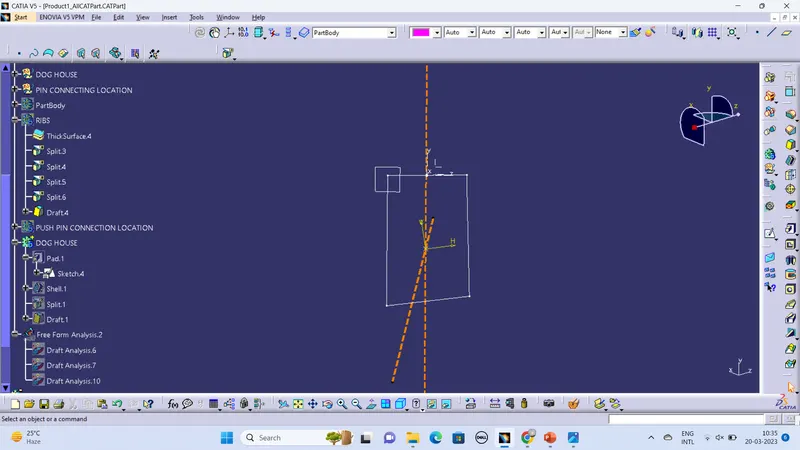
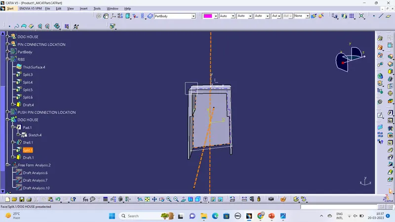
DRAFT ANALYSIS
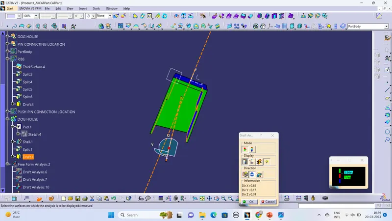
RIBS AND ITS ANALYSIS
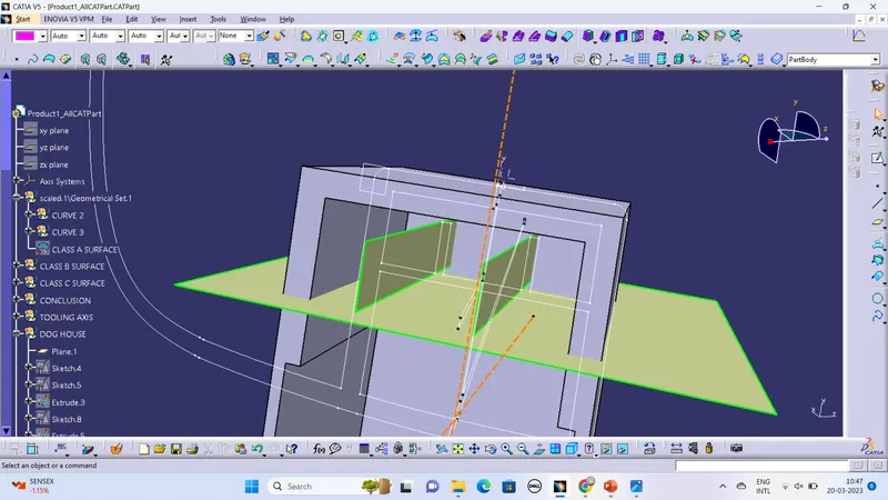
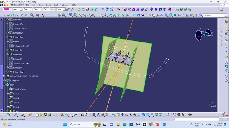
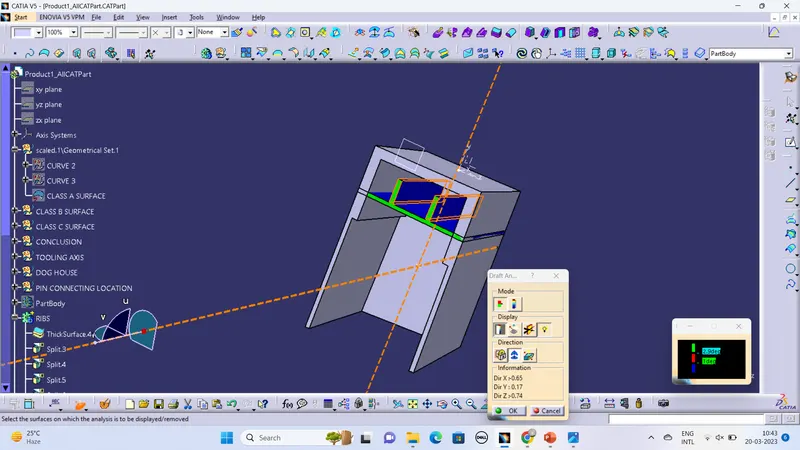
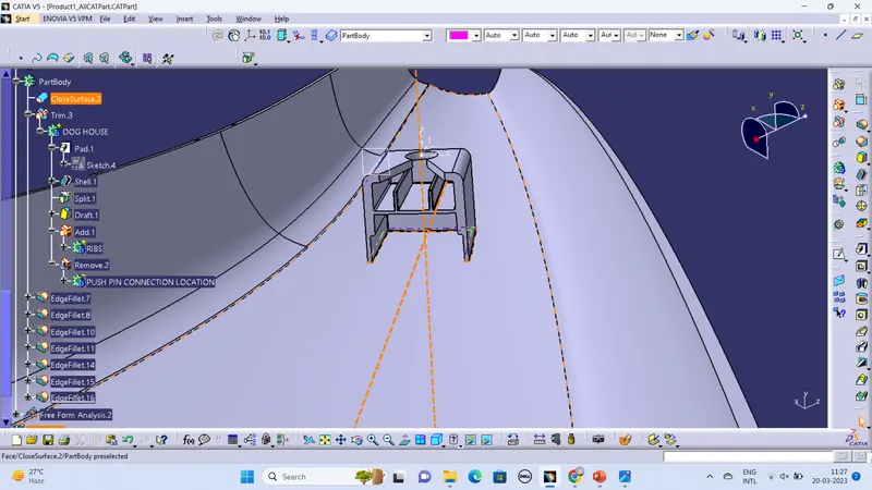
PUSH PIN CONNECTION LOCATION
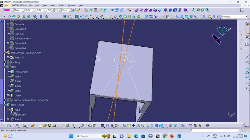
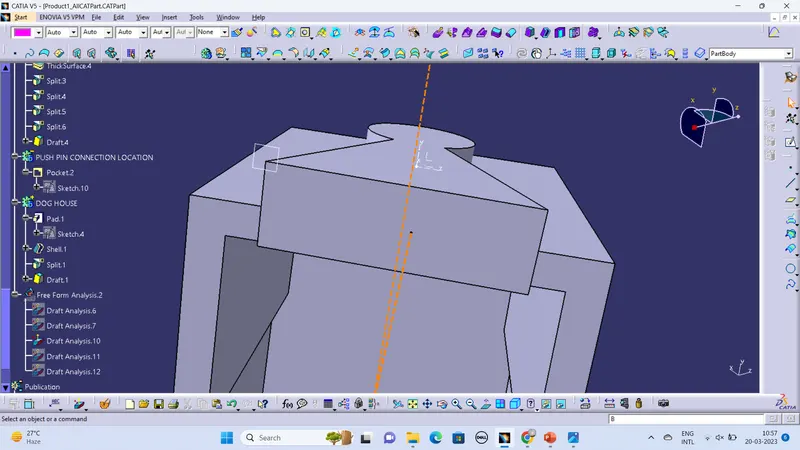
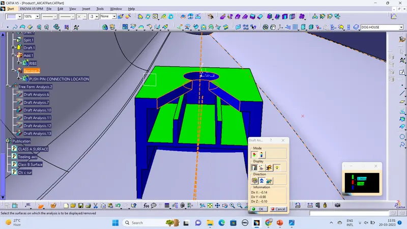
JOINING THE PARTS AND FILLETS
Various views of end product