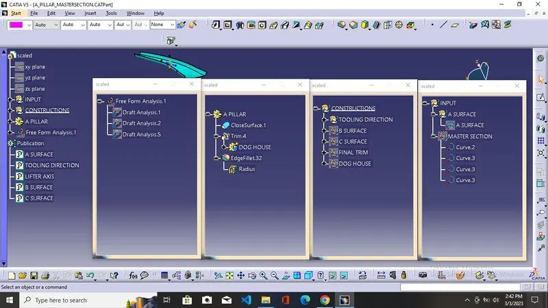
Week 9 - Project - A pillar Design with Master Section
Ans 1
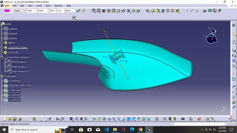
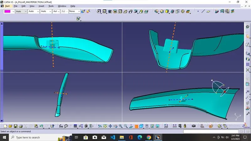
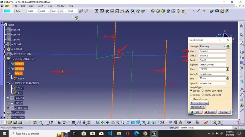
TOOLING AXIS = It is the axis or direction along which the core and cavity move and the required part ejected along this direction. In this question, we are going to explain making tooling axis by BISECTING method.
STEP 1
Extracting two lines along the intended direction for the formation of the tooling axis.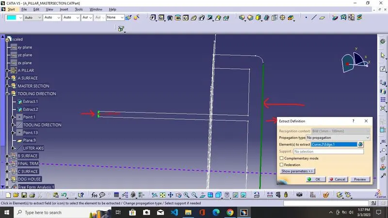
STEP 2
Making the point between both the lines using the point option with between as the sub-option.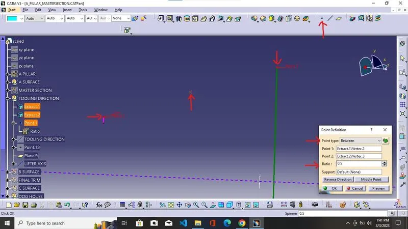
STEP 3
Formation of the tooling axis using the line option and bisecting as a sub-option and selecting the two already extracted lines as a reference line and the above point as a reference point.
If it clears the draft analysis test then the tooling direction is correct.
DRAFT ANALYSIS = It gives us information about the parts which tells us which part clears the mold walls easily so as to minimize the machining process in the finished product and final product ejected easily and minimize the contact between the product and mold walls.
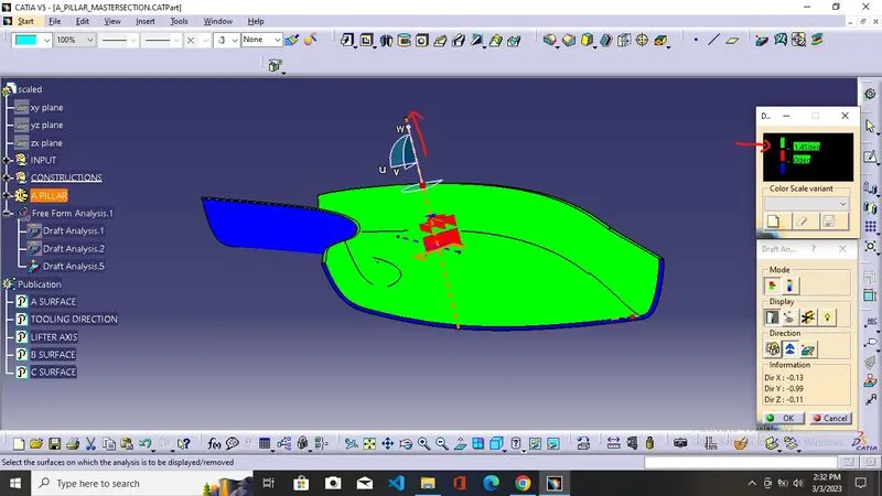
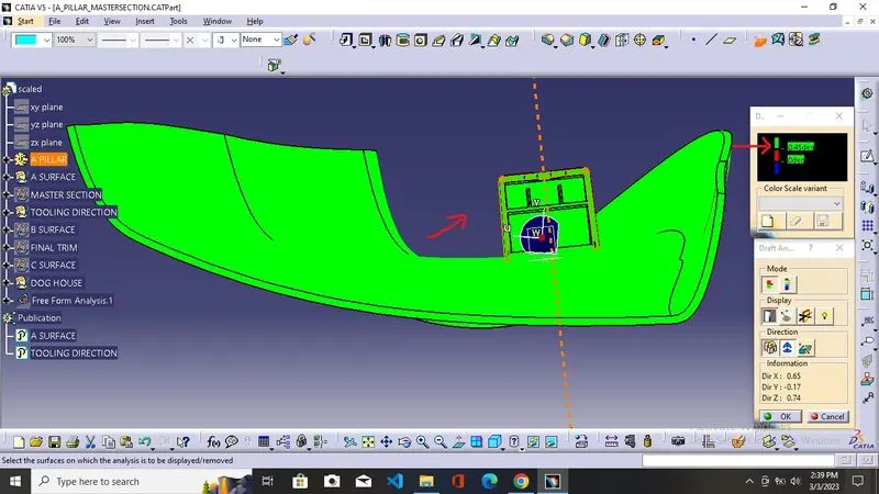
STEP 1 = Select the Feature draft analysis tool and move the compass to the tooling direction and align the compass w axis to the tooling axis. After aligning the compass with the tooling direction again click the compass tool to insure the proper alignment of the w-axis with the tooling axis. After the proper alignment uses the locking tool to lock the compass with the tooling axis.
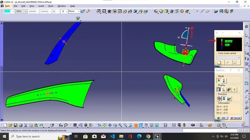
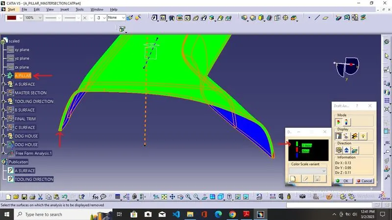
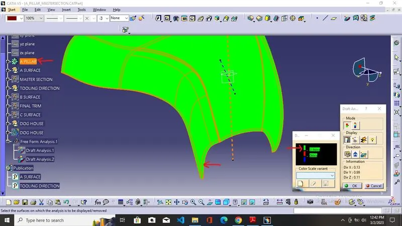
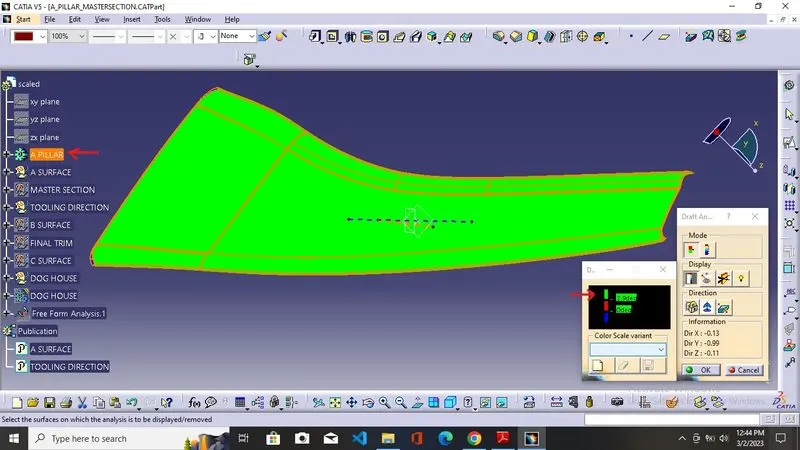
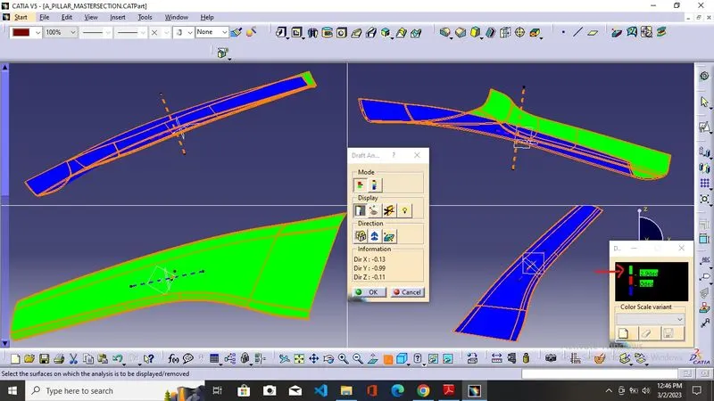
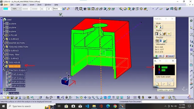
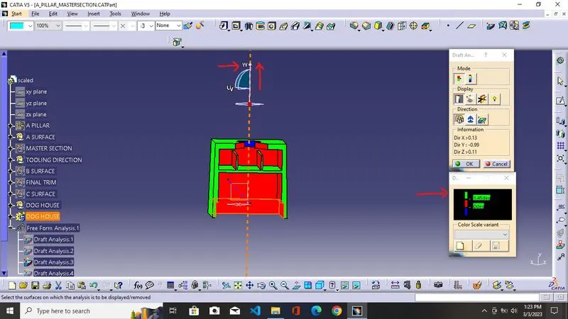
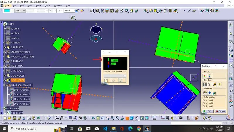
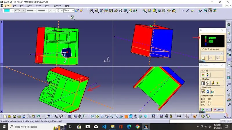
STEP 2 = Click anywhere on the A surface to generate the draft analysis report and use the quick analysis mode option to see the color code values where the green color defines the parts which have a draft angle greater than the green color code value generally it is up to 3 degrees in values. The red color gives information about the parts which have angles between 0 to up to a green color value which is generally up to degrees. The blue color gives information about parts that have an angle less than the red color. If A surface comes out in green color means our tooling axis is perfect and we are ready to go for the formation of B and C surfaces.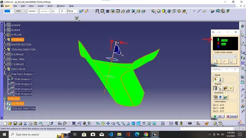
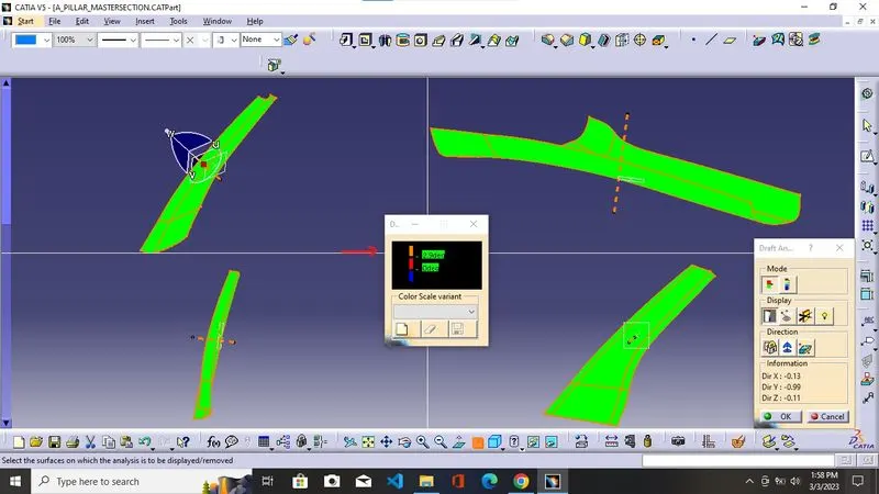
Here all surfaces of the A-pillar clear the draft analysis test hence the tooling axis is correct.
Closed Surface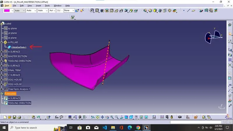
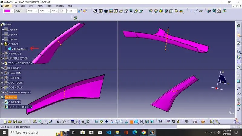
Draft Analysis of closed surface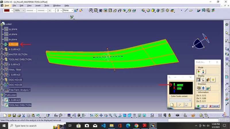
Dog House
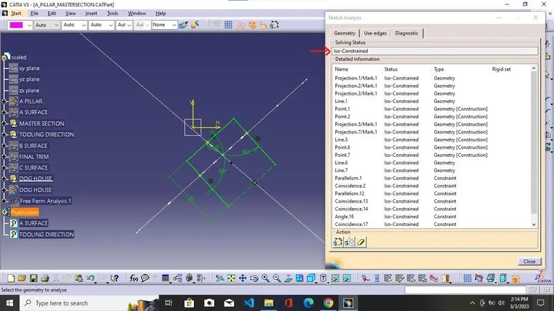
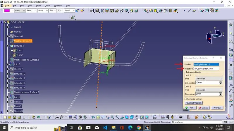
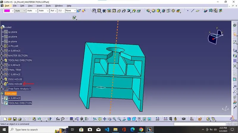
DOG HOUSE = Dog house is an engineering feature used in the plastic trim design. Dog houses are used as supporting features. It also uses when we want to use the screw boss at a large distance to prevent the buckling of the screw boss under the load and to reduce the sink marks on the surface.
FINAL PART