Project - A pillar Design with Master Section
1. Aim
To Create an Solid Component along with an Engineering Feature namely Dog House from the given Class A surface and Mastersection. Also the Engineering or B side Features should be designed as per the Design Standards.
2. Master Section
While Considering an Launch of an New Automative Car, it doesn't mean that everything in that car will be completely brand new. The things which are visible to the customer is only new and all the other inside mechanism would be pretty much similar to the old model with slight modifications. Those inside mechanisms and features would be implemented into the new theme with the help of Master Sections. These Master Secions are provided by the OEM based on the old models. Design Engineer should be designing the Component and other features with referencee to that Master Sections.
3. Dog House
When a Plastic Component has more than a 3mm of thickness, then it has an possibility of creating an Sink mark in the Class A Surface which can spoils the component's aesthetic look. In these regions Dog House can be helpful at the same time it can act as an supporting feature too. It has certain design rules to be followed while designing like,
- It should have a minimum height of 12mm
- Dog house wall thickness at intersection of part wall should be 40% or less than main wall thickness
3. Procedure
3.1 Work Flow Pattern
- Creation of Tooling Axis
- Creation of B Surface
- Creation of C Surface
- Creation of Dog House
- Assembling
- Draft Analysis
3.2 Creation of Tooling Axis
For the Creation of Tooling axis, Bisecting Method was used. Since we have an Master Section, It should be designed with reference to it. And also the Master Section would also have an Tooling Axis, to find that right Tooling Axis Bisecting Method was used.
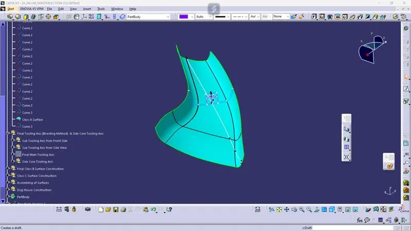
While Performing the draft analysis, Class A Surface clears at 3 degree of draft.
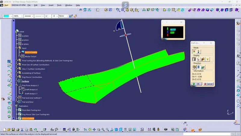
3.3 Creation of Class B Surface
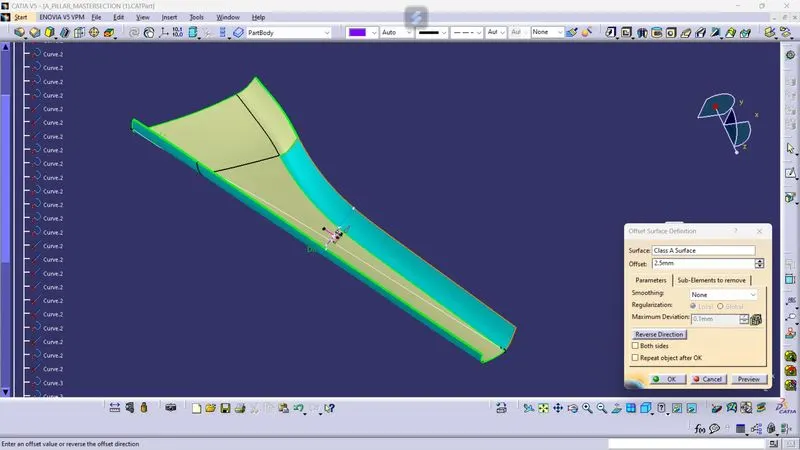
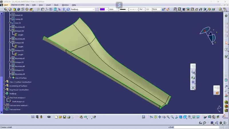
The thickness of the component is taken from the reference of Master Section and it is 2.5mm. With this the class A surface was offseted to 2.5 mm to create class B surface. While offseting, some surfaces got convexity error and it was not offseted. To create the unoffseted surfaces, it was swept along reference to surface method.
Offseted Class B Surface:
Final Class B Surface:
3.4 Creation of Class C Surface
Class C Surface is nothing but the surface which joins Class A and B. For the Creation of Class C Surface
- The surface which are perpendicular to the tooling axis will be Sweeped along reference to surface method at 90 degree angle.
- The surface which are parallel to the tooling axis will be Sweeped along draft direction method at 3 degree angle.
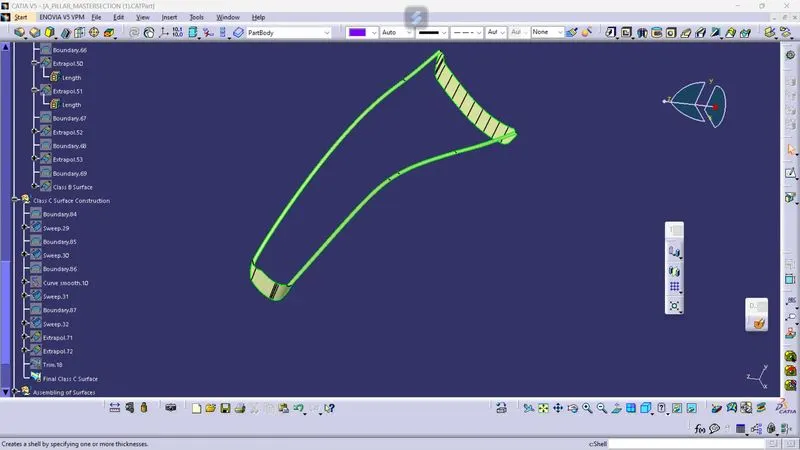
After the Creation of Class C, Class A and C surface was joined and trimmed along the Class B Surface to create the final Closed surface.
Then in part workbench it was converted into Part by using Close Surface Tool.
Class A and C Surface:
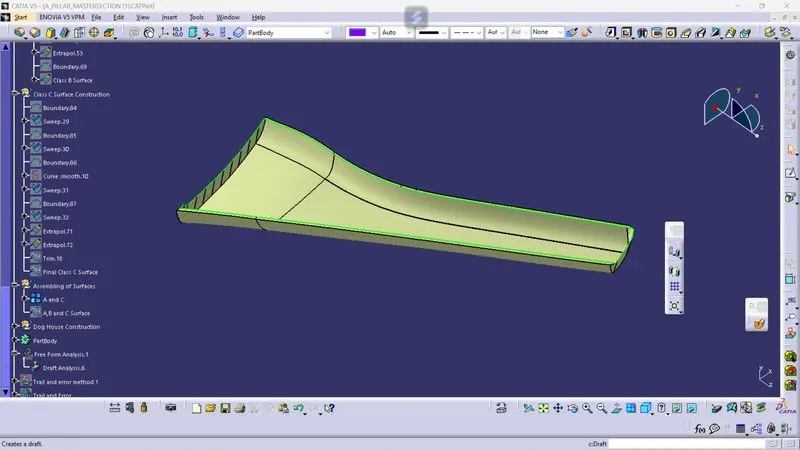
Final Close Surface:
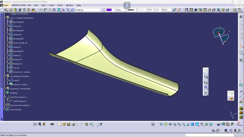
3.5 Creation of Engineering Features
In this Challenge, the master Section has an Dog House and it was created with the reference of the Master Section. All the Points and lines which are taken as reference were isolated to prevent the relation from the Master Section.With this any modification or deletion of the Master Section would now affect the Cat Part.
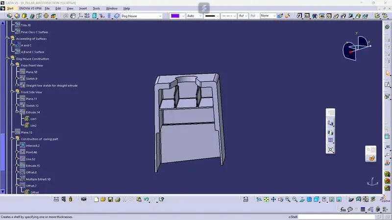
3.5.4 Dog House
For Dog House,
- Wall Thickness - 2.5mm
- Core Wall Thickness -1mm
- Outer Wall Fillet Radius - 1.5mm
- Inner Wall Fillet Radius -0.5mm
- Core Wall Fillet Radius - 0.25mm
- Main Tooling Axis Draft Degree - 1.49 degree
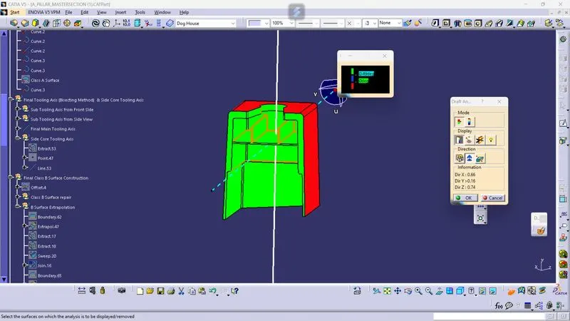
- Side Core Tooling Axis Draft Degree - 0.49 degree
Sketch:
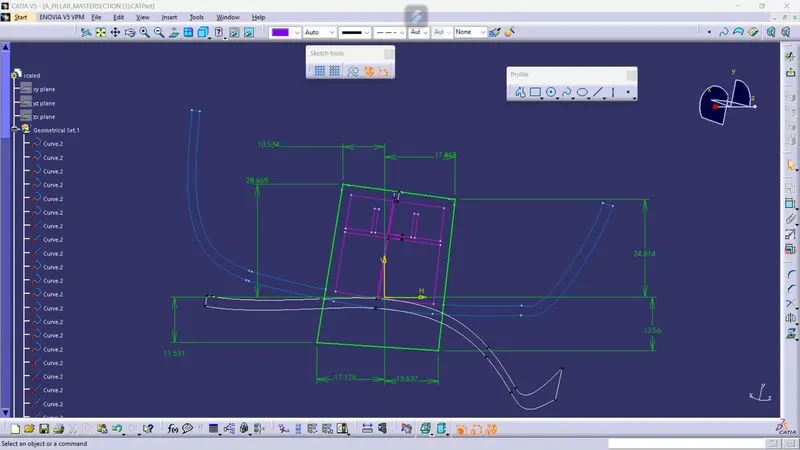
Design:
3.6 Assembling
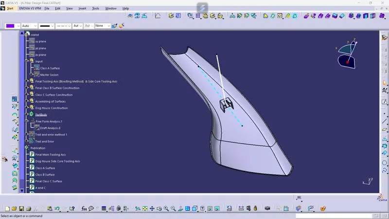
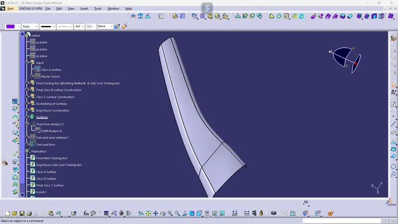
After the Thickening method all the parts were assembled into the Main Part by using Boolean Operations.
Final Part:
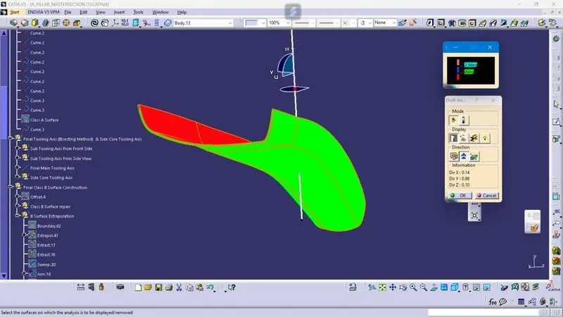
3.7 Draft Analysis
3.7.1 Draft Analysis on Final Part
On the Final part, draft analysis was performed at 2.9 degree.
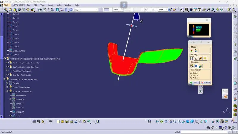
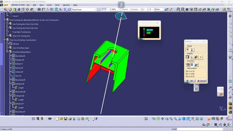
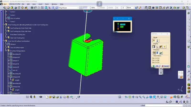
3.7.2 Draft Analysis on Engineering Features
Draft Analysis of Dog House from Main Tooling Axis at 1.49 Degree:
Draft Analysis from Side Core Tooling Axis for 0.49 Degree:
4. Conclusion
With the given Class A surface as an input, Tooling Axis, Class B Surface , Class C Surface and the Dog House were Created. Also both the Final Component and Engineering Features were clearing the Draft Analysis.