Bumper Design
1. AIM
To Create a Part body from the given Class A Surface as an input.
2. Other Objectives
- Creating tooling Axis
- Creating Class B Surface
- Creating Class C Surface
- Should Perform Draft Analysis
3. Class A Surface
Class A Surface is a surface with Aesthetic shape and No Thickness. After the completion of concept sketch, the image will be imported to a class A Surface creation software like Alias and the A surfaces will be created.
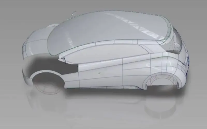
Later, it will be given to an Plastic designer to give it's Thickness, Draft and other Engineering features.
Before starting to design, the Plastic designer should verify all the Class A surfaces, whether they are intact or not.
If the input Class A Surface's are not intact then the plastic designer can try to join the surfaces from 0.001mm to a maximum of 0.003mm. If it's not cleared the maximum join length of 0.003mm, then with no further modifications, it will be reported and sent back to the Class A Surface designer.
4. Creation of Tooling Axis
The Tooling Axis is simply refers to the Direction where the Mold Opens and Closes. The part draft should be given along the tooling axis. Selecting the tooling axis will be a crucial one because it should be created in a way of clearing the draft analysis of the Class A Surface and the final part.
Usually there are Three methods of choosing the tooling axis direction and they are
- X, Y, Z direction
- Normal to Surface and
- Bisecting Method.
5. Draft
In Plastic Molding, the property of every molten Plastic material is that when it solidifies, it will tries to clinge on to the core or the surface.
Usually when an plastic component molded without any draft angle then, it will undergoes much friction with the Core and Cavity section.
This will leads to lots of wear and tear, then gradually leads to the damage of the Core and Cavity.
Also the part which is created without draft, will have some unpleasant surface finish and it also can be deformed.
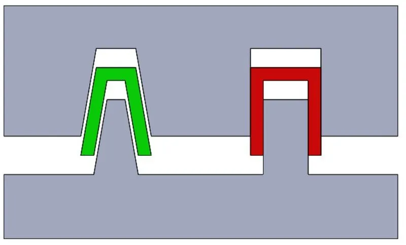
So, to avoid these issues draft angle will be given to the part. That is why , every plastic component which undergoes injection molding process will have a minimum of 0.5 degree draft angle. But still manufacturing such a precise component will be very costly and have to spend lots of money.
So, the Plastic Manufacturing industries usually prefer to use 3 degree of draft angle for normal surfaces and 7 degree of draft angle for textered surfaces.
6. Procedure
The steps followed in the process of making the Final Part body.
6.1. Class A Surface Check
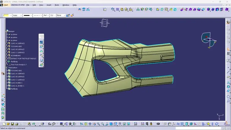
Input of the class A was in the STP Part file type and all the Class A Surfaces are intact to eachother without any open boundary within the Surfaces. Also it was verified by using Boundary Tool.
6.2. Tooling Axis Creation
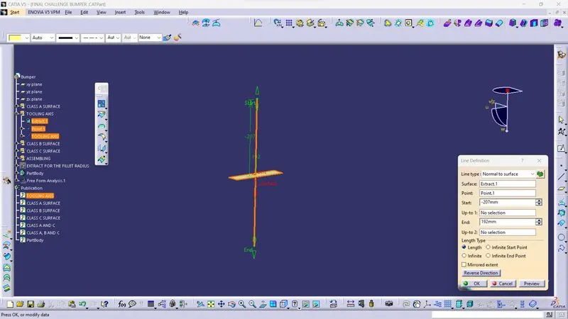
For the creation of Tooling axis for Coin Holder, Normal to surface method was used.
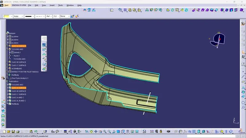
This class A Surface has a curve like surface with so many surfaces. So, either X,Y & Z method and Bisecting method cannot be used. With any flat surface which covers most of the Class A Surface can be used as the base for creating Tooling axis.
6.3. Draft Analysis of Class A surface
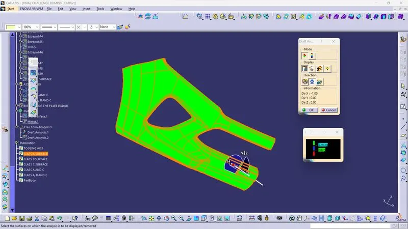
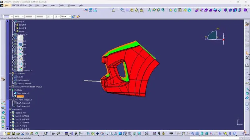
With the Main Tooling Axis created, draft analysis was performed on the Class A surface with the nominal draft angle of 2.9 degree and it was getting clear. In the Analysis, Green colour refers that the 2.9 degree of draft angle can be performed in this direction.
6.4. Class B Surface Creation
After clearing the draft analysis the each surface's of the Class A was extracted except the filleted surface and then it was offseted to a distance of 3mm which is the final component's thickness. In this Challenge, the whole Closed surface was directly offseted to 3mm. As a result some minute fillets was gotten convexity error and it was offseted. These sections were overlooked and gotten repaired by extrapolating and Trimming method.
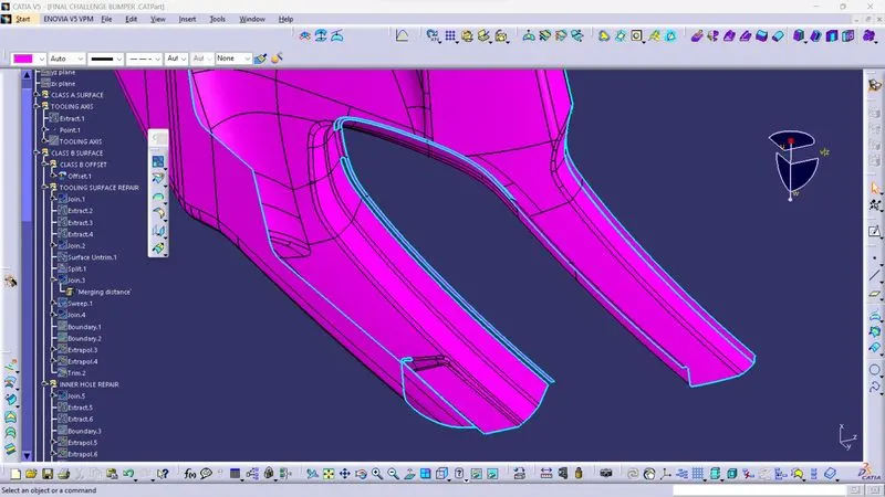
For the fillet radius, the fillets which are in outward direction, the thickness was added with the actual fillet radius and for the fillets which are in inward direction , the thickness was subtracted with the actual fillet radius which is taken from the Class A Surface as reference.
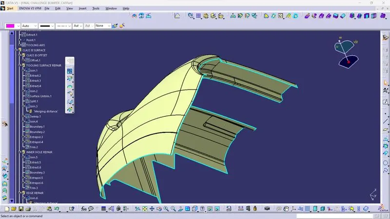
To get the exact fillet radius of the Class A, the fillet regions of the class A was extracted and then it was untrimmed and measured to get the acurate fillet radius.
6.5. Class C Surface Creation
Class C surface can be created with two methods.
- If the Class C Surface was perpendicular to the Tooling axis then it will be created by using Reference to Surface method at 90 degree of angle along tooling axis direction.
- If the Class C Surface was Parallel to the Tooling axis then it will be created by using Draft Direction method at 3 degree of angle along tooling axis direction.
In this Challenge, both Reference to Surface and Draft Direction Method was used.
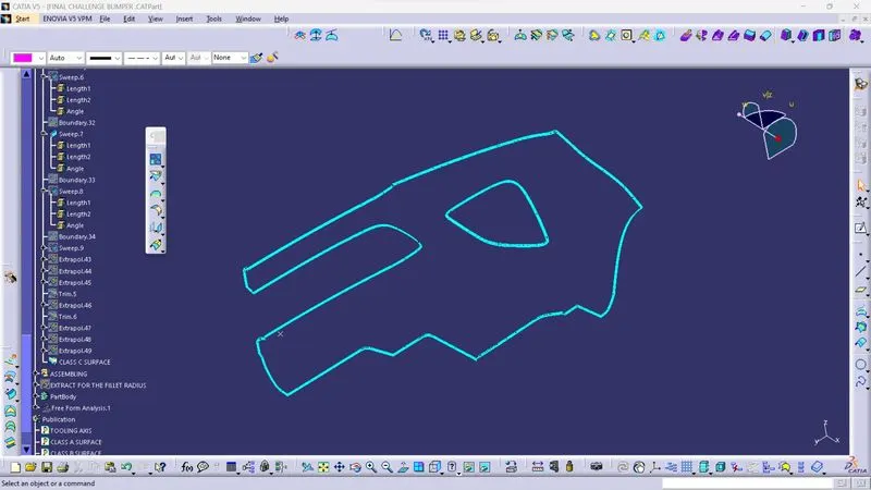
Using Sweep tool , the extracted edges as guide curve along draft direction at 90 degree of draft angle , Class C Surface was created except the inner whole section. In that section Class C surface was created with Direct direction along the tooling axis at 3 degree of draft angle.
6.6. Final Part body
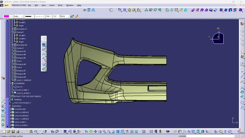
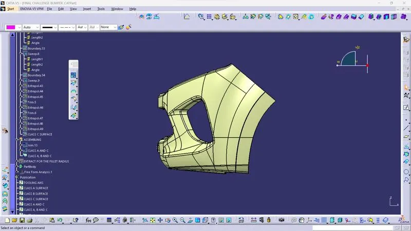
After the creation of Class A, B and C Surface, Class A and Class C surface's was joined and renamed as Class A+C Surface.
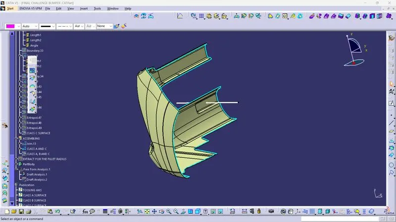
Then finally, the Class A+C Surface was trimmed along the Class B Surface to get the final Close surface of the Part.
Isometric View:
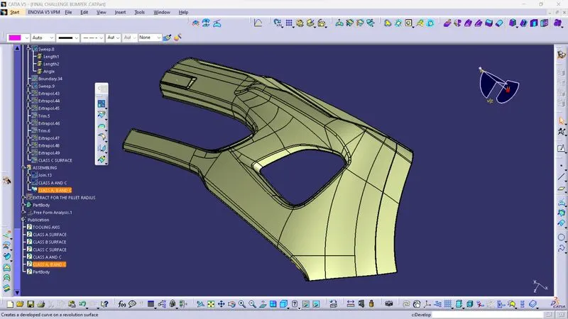
Top View:
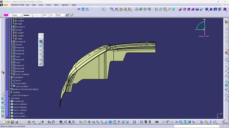
Front View:
Side View:
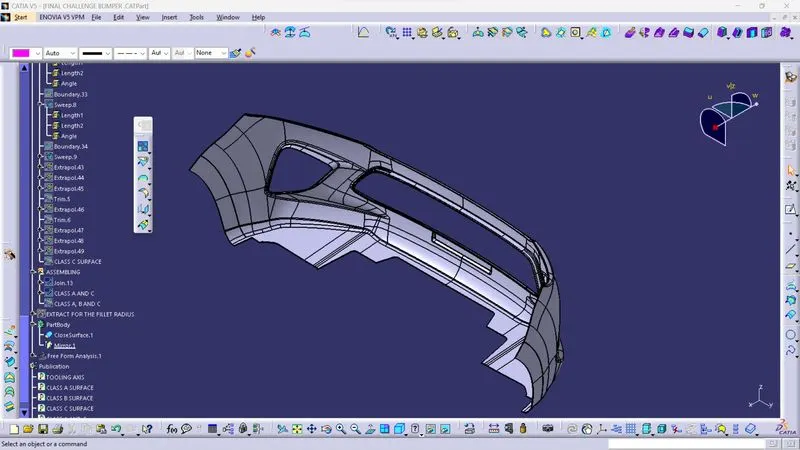
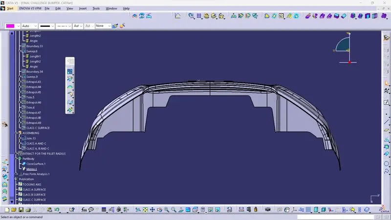
Then moving to Part Workbench, Using Close Surface Tool , the Close surface was converted into a Partbody.
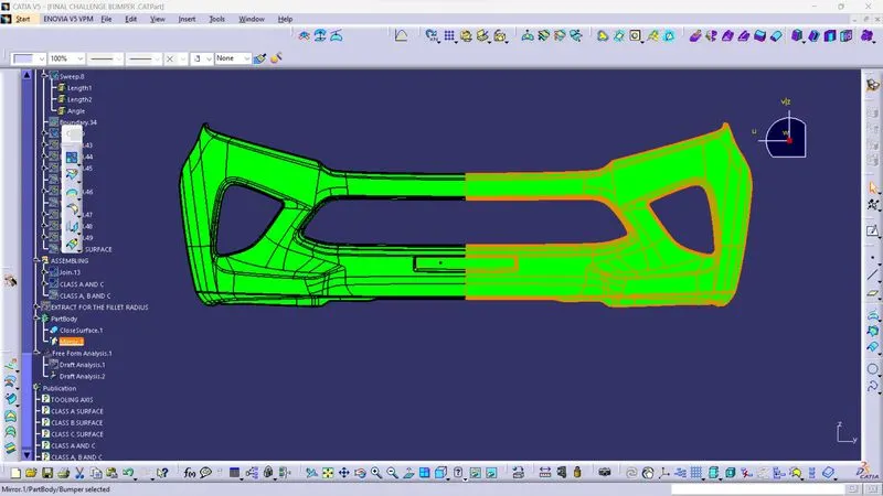
After Converting into part, use symmetry tool along zx plane to mirror the other side.
Isometric View:
Top View:
Front View:
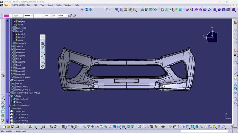
Side View:
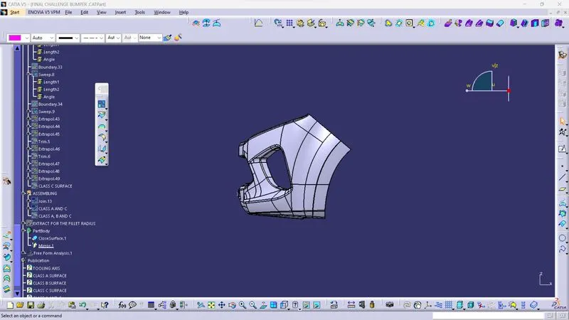
And there was a final draft analysis on the partbody along the tooling axis to make sure the Class A and C Surface along the tooling axis at 2.9 degree of draft angle gets cleared or not.
7. Conclusion
Isometric View:
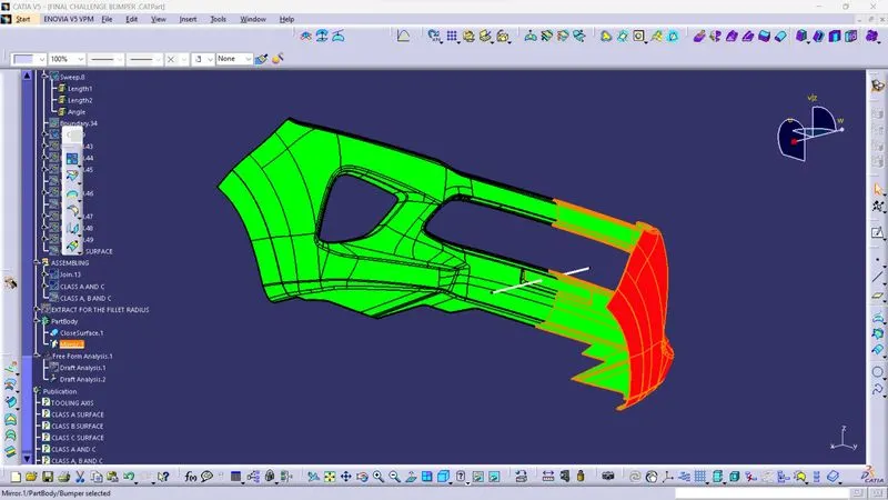
Top View:
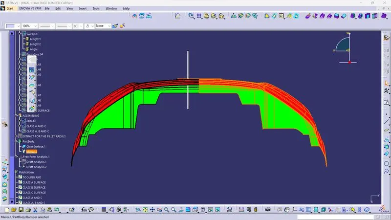
Front View:
Side View:
Draft Box Details:
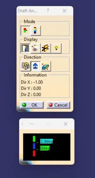
Tooling Axis was created. Class B and C Surface was Created. Part body was created with the input of Class A. Final part body clears the draft analysis along Class A and C surface direction at 2.9 degree of draft angle. Thickness of the part is 3mm.