Week 9 - Project - A pillar Design with Master Section
Aim - This project aims to create a Pillar Design component using the given class A surface with Master Section following the OEM standard. and perform the draft analysis.
Objective -
- Ensure Proper Tree Structure.
- Geometrical sets should have a proper name based on the sketches present inside them.
- All the sketches should be created under the Geometrical set.
- Use the Close Surface feature to make a solid body from the surface.
- To publish the Tooling Axis, Class A,Final Product.
Design Methodology -
- Insert the class A surface of the A pillar design and its master section in CATIA software.
- Determining the tooling axis for the A pillar design
- Creation of class B surface.
- Creation of class C surface.
- Join the Door Trim Lower's class A, class B, and class c surfaces and ensure all the surfaces are closed surfaces.
- Use the Close Surface feature to make a solid body from the surface.
- Create dog house with help of Master section.
Theory -
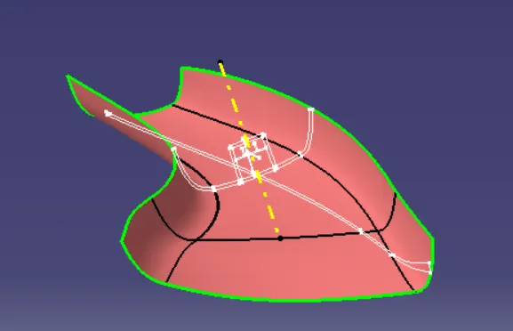
1.Tooling Axis - Generally 3 methods used to create the tooling axis.
- Normal to plane (Large surface avilable).
- Bisecting the line.
- Point and Direction.
For A Pillar Design master section is given so we used master section to create main tooling axis and Class A surface clears in draft analysis.
2.Class B Surface -
To create the class B surface, offset the class A surface inside as per our thickness requirement (here the master section given and thickness is 2.5mm, so offseted the class A to 2.5 mm inside). Once the offset is created, we can observe some patches on the offset surface by taking the boundary for the offset surface, those patches are formed due to the fillets on the class A surface. We need to cover those patches with the help of the multi-section surfaces command by extracting the patch boundaries. Once all the patches on the offset are covered properly join all the patches with the offset surface, to get the replicated surface of the class A surface.
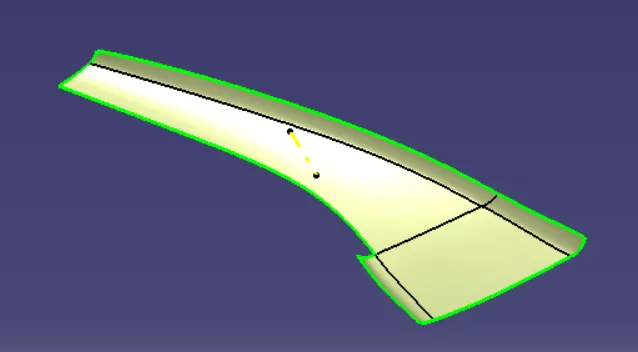
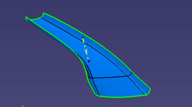
Fig. After giving offfset Fig. After filling pathes Class B
3. Creation of C Surface -
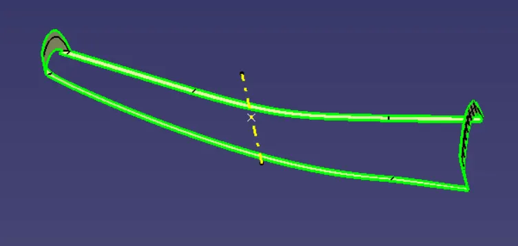
The edges of the Class-A surface are extracted using the multiple extracts and surface that are parallel to the main tooling axis are made with sweep draft angle 3 degree and surfaces that are perpendicular to the main tooling axis are made with sweep referance surface.At last join the all surfaces.
4.Final Trims -
Joining the Surface A + Surface B + Surface C
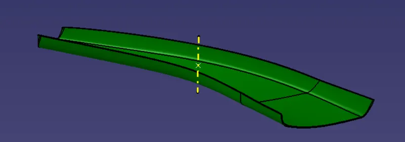
And last Close the surface.
5.Dog House -
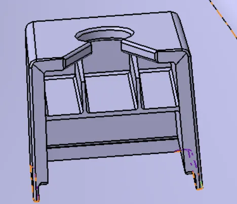
Dog house is an engineering feature used in the plastic trim design. Dog houses are used as supporting features. Sometimes other engineering features like snaps; locators, etc. are mounded on them to increase their strength. Dog house and other engineering Features are built on B-surface.
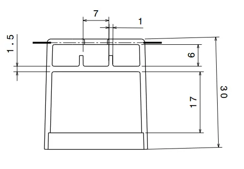
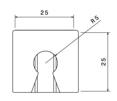
With help of above design rules and master section created dog house following OEM standards.
6.Draft Analysis -
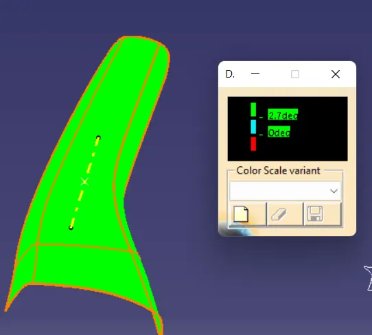
Draft Analysis is used to check the whether the minimum draft of 3deg is maintained or not and for engineering features its 0.5deg.The draft analysis command enables you to detect if the part you drafted will be easily removed. This type of analysis is performed based on color ranges identifying zones on the analyzed element where the deviation from the draft direction at any point, corresponds to specified values.
1.Draft Analysis of Class A -
2.Draft Analysis of Final product -
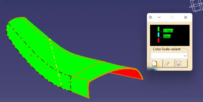
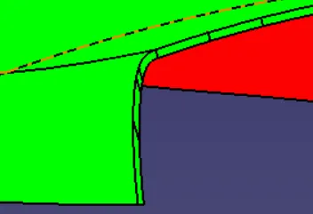
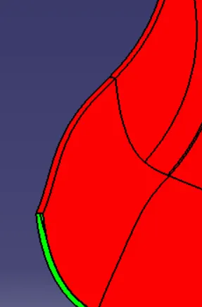
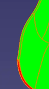
As we can see the c surface parallel to the main tooling axis it get clear with class A but perpendicular is not.In A pillar Class C is getting overlapped with class A so it get cleared with Class B.
3.Draft Analysis of Dog House -
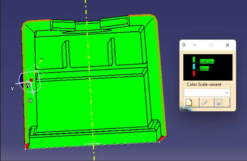
4.Draft Analysis of Final product with dog house -
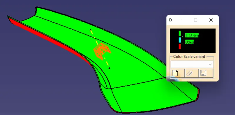
As 1.5 Draft is given for dog house so taken analysis for 1.4degree.
Conclusion -
Succesfully created A Pillar Design component using the given class A surface with Master Section following the OEM standard. and performed the draft analysis.