Week 9 - Project - A pillar Design with Master Section
Aim :
To create a A_Pillar design using Master sections with design considerations along 2.5mm thickness.
Given Data :
- A Class surface.
- Master sections.
- Thickness 2.5mm
- 2d drawing of Dog house.
MASTER SECTION:
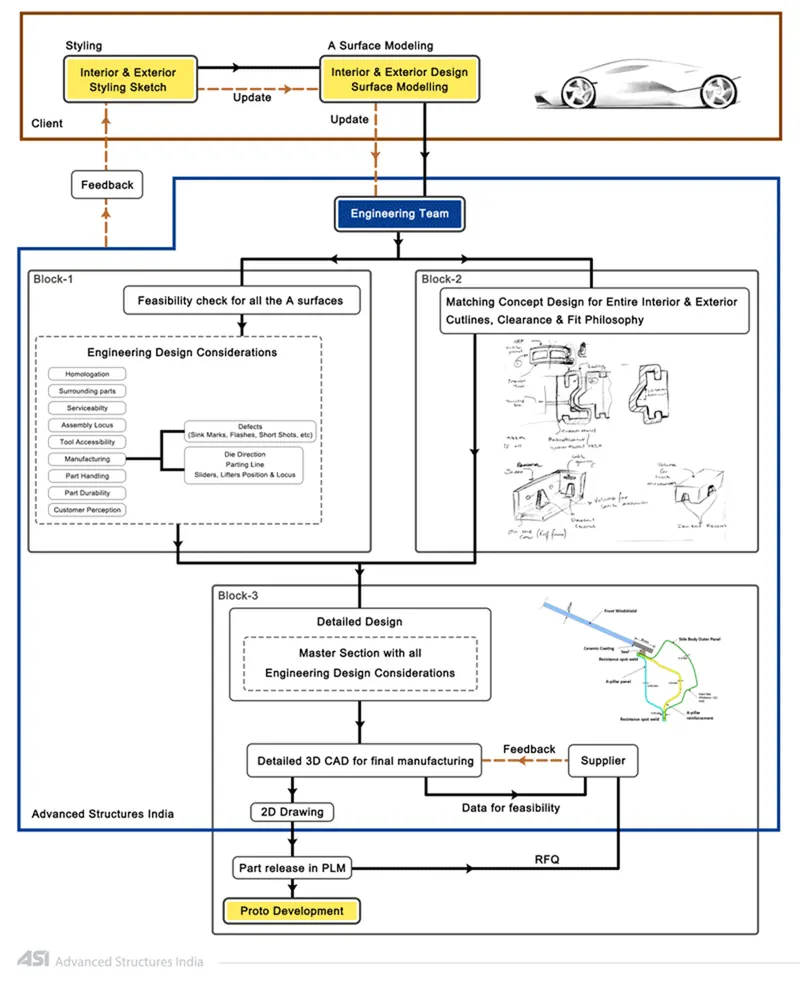
Master sections development takes place during feasibility check and concept validation stages of the product life cycle. These are typically the guides for design requirements and which decides the component packaging after the development of the concept design, i.e class A surfaces.
Master section helps us to decide the feasibility of the concept design, the clearances, the packaging and the fixation strategy of a component before converting the concept design into a solid 3D engineering design.
During the period of vehicle concept design the evaluation of the master section performance depends mainly on the reference vehicle data and experience of structure design engineer.
Class A surface :
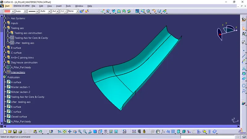
- First we need to check the Class A surface for patches.
- If there are any patches we need to improve the surface of Class A.
- No patches are found and Surface is good.
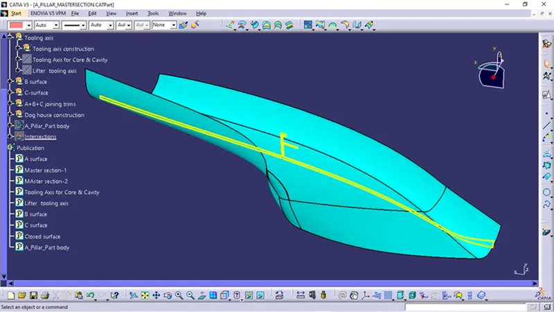
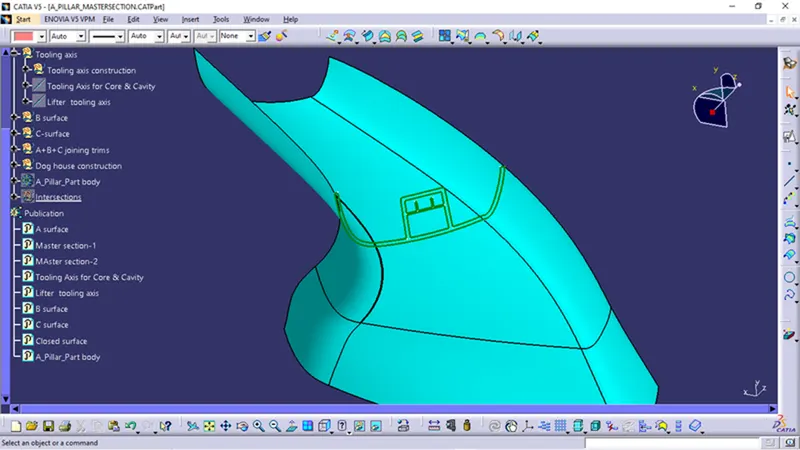
Master sections Given :
Tooling Axis :
- Tooling axis is the direction in which mould (or) core & cavity opens.
- Basically one main tooling axis will be given to a Part.
- Depending upon the criticality of the part sometimes the another tooling axis is aslo shown called as Side core tooling axis or Lifter tooling axis.
- This Side core tooling axis is the direction of side core.
- In this part we need to provide both tooling axis.
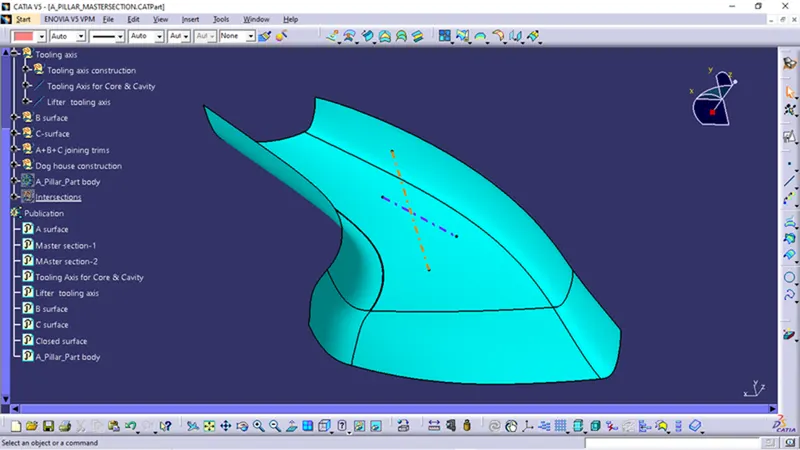
* Orange center line is Main Tooling Axis.
* Purple center line is Lifter Tooling Axis.
Draft Analysis :
- Draft Analysis to be done to Class A with 3degree draft along tooling axis weather the surface is passing our tooling direction or not.
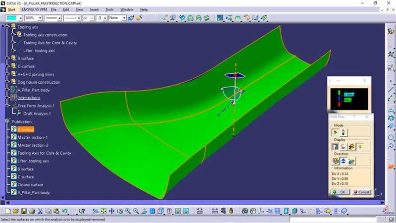
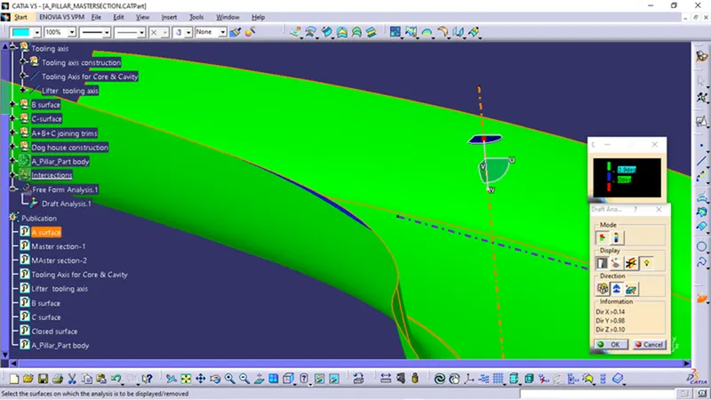
- A small area is not passing our draft analysis with 2.9degree draft which is in blue colour.
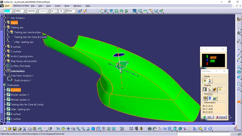
- But the same area is passing our draft analysis with 2.6degree draft.
- It is negligible and no need to worry about small area with variation of below 0.5degree.
Class B surface :
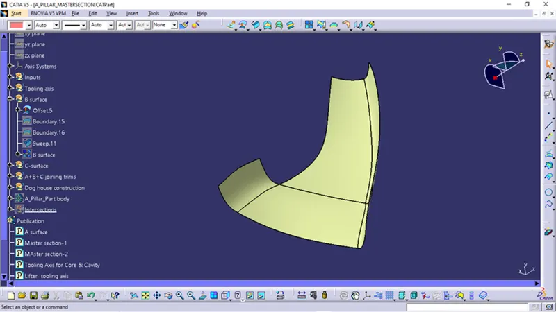
- B surface creation is depending on thickness of part.
- The part thickess is 2.5mm and we need to offset the Class A surface to 2.5mm.
- Some patches may occur while making offset.
- Patches to be covered and make a good surface.
Class C surface :
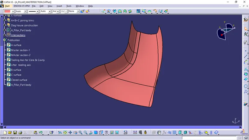
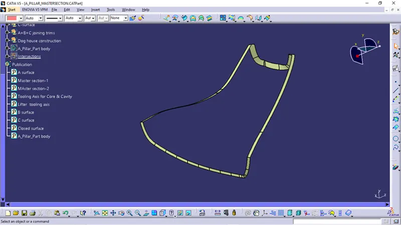
- It is the surface which joins Class A and Class B surface.
- While creating class C surface we need to remember the parting line of mold and design the class C.
- Parting line should always comes in to Class B surface side.
Joining of Class A +Class B +Class C :
- These three surface join and trim and make a closed surface body.
- It is done to make a part body.
- If the surface is not closed properly then the part body will not be created.
- Ensure proper closing surface.
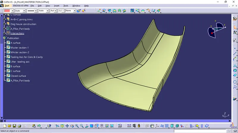
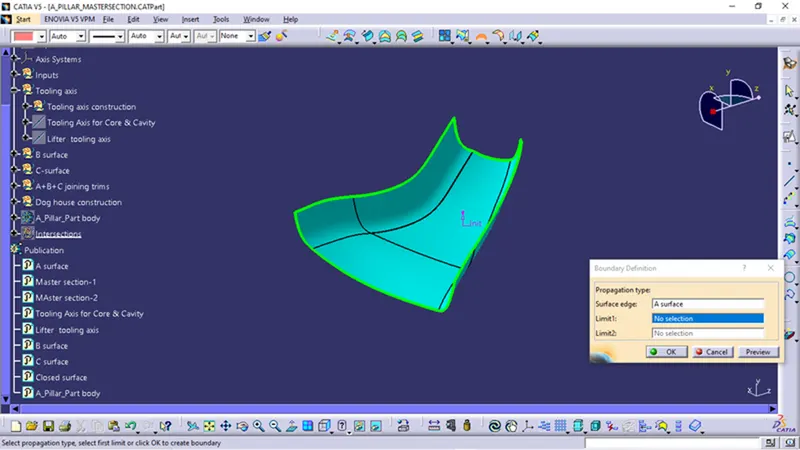
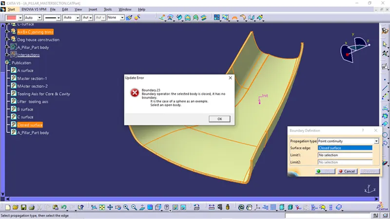
- We can check weather it is properly closed or not by using boundary feature.
- If the error dialouge box appears then the surface is perfectly closed.
Part Body :
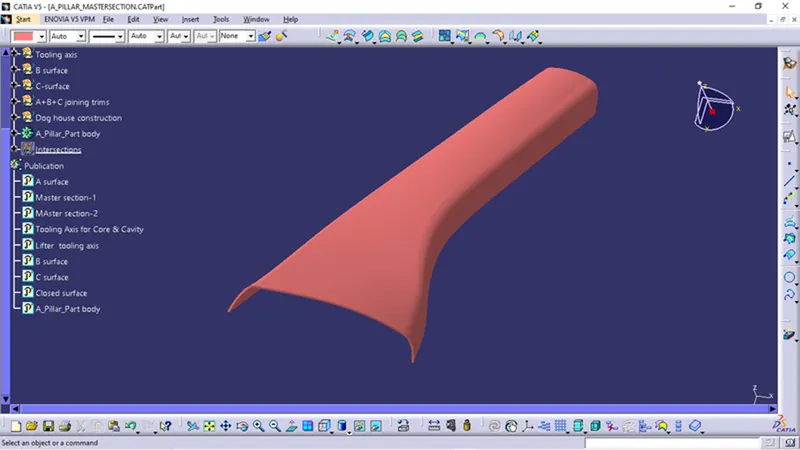
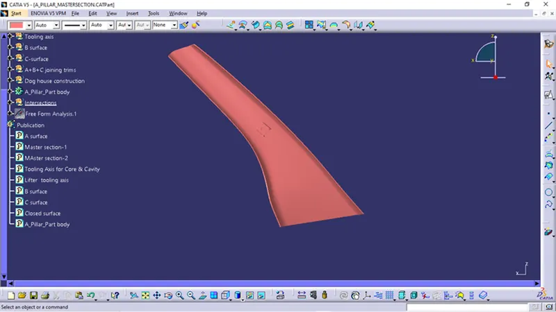
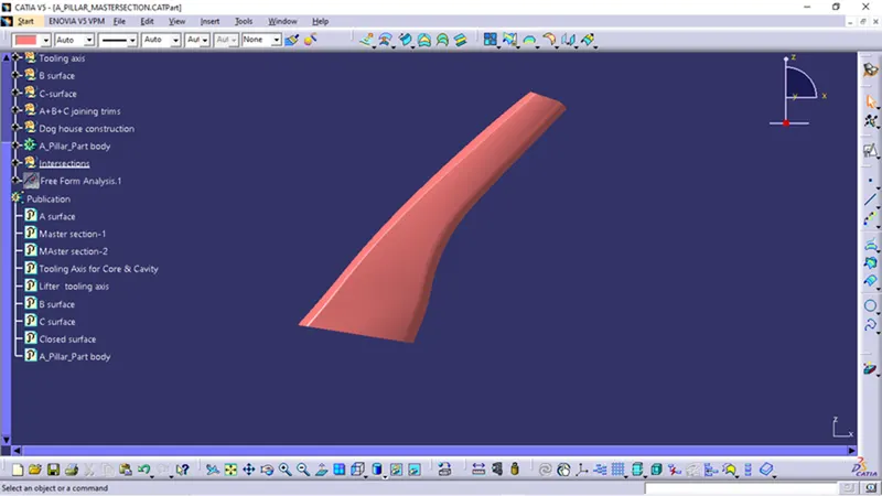
- After Closing the three surfaces we need to convert the closed surface to a part body by using Close surface feature in PART DESIGN workbench.
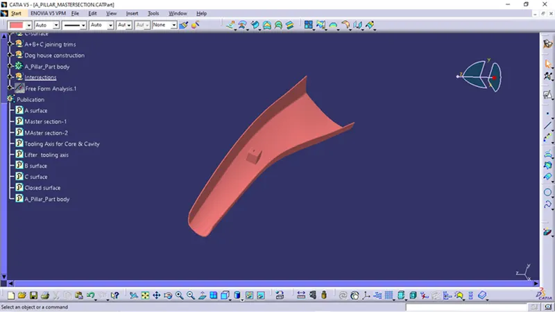
Dog House :
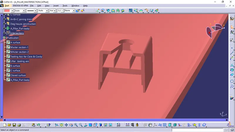
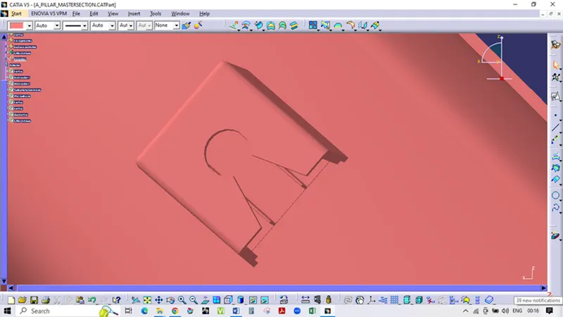
- Dog house is an engineering feature used in plastic trim design.
- Dog houses are used as supporting feature. Sometimes other engineering features like snaps; locators etc. are mounted on them to increase their strength.
- Dog houses are subjected to draft analysis to prevent breakage of the component during ejection from mould cavity.
- Dog house and other engineering components are built on B-surface.
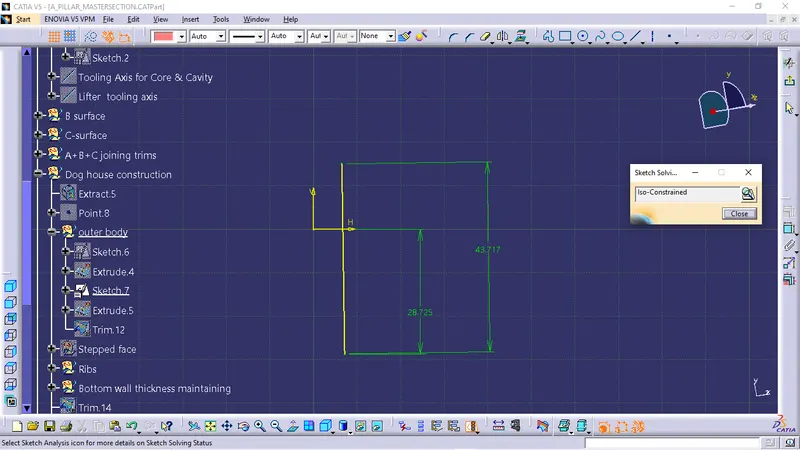
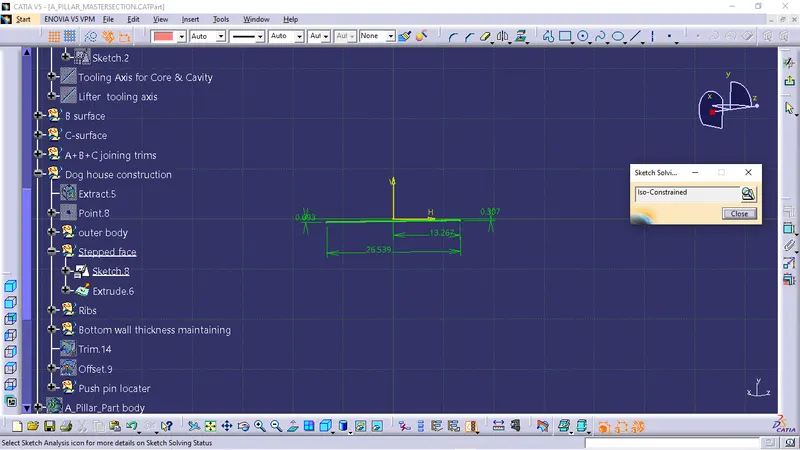
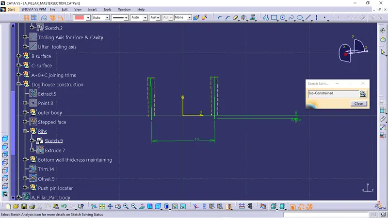
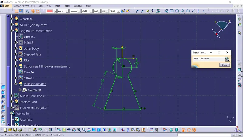
- This dog house creation is done by using given master sections along Lifter tooling axis.
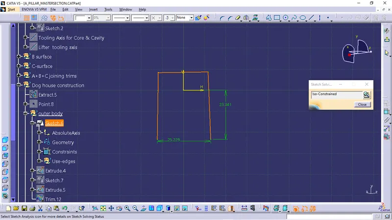
Sketches for Dog House creation :
- Ensure that sketches should be iso-constrained.
Draft Analysis :
- Draft analysis to be done on part body with 3degree draft angle along main tooling axis.
- When draft analysis is done with 3degree draft angle,
From Class A side :
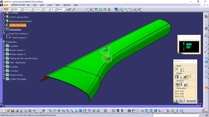
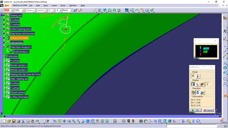
Hence it is a small area it is acceptable.
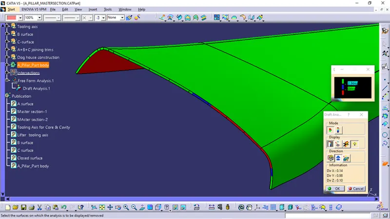
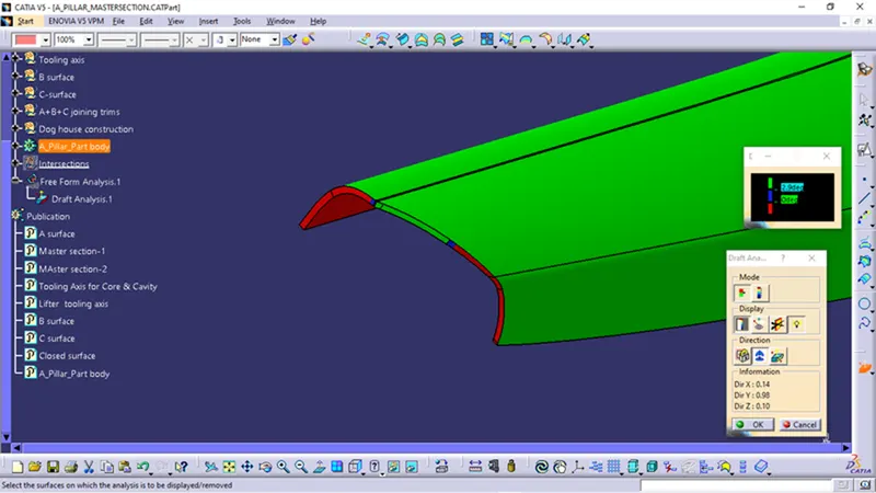
- The above shown Class C surface should also pass the draft analysis but this is not happening.
- Because of improper Class A some areas of Class C surface is not passing draft analysis.
- I have been tried two to three methods for creating Class C for passing the draft analysis, but the result is same.
- If Class is proper and good then the class C surface will pass in draft analysis in one of the method creation.
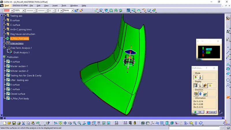
From Class B side :
- This is done with 3degree draft angle.The dog house draft angle is lesser than bigger surface.
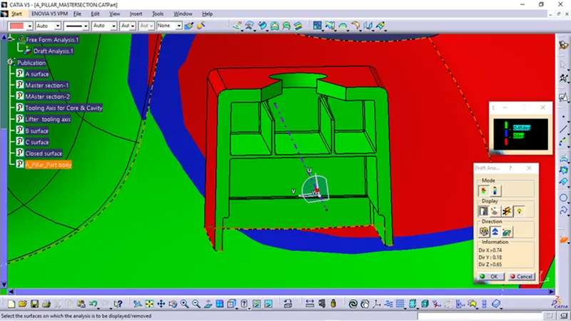
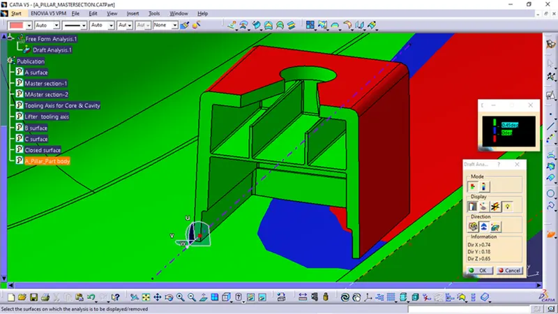
For Dog House :
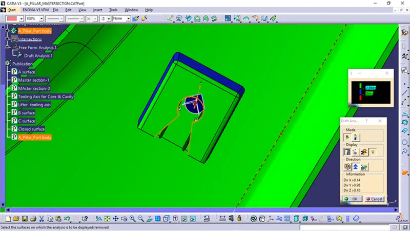
- The dog house is created based upon design considerations and the draft angle is 0.5degree.
- Draft analysis done to dog house with 0.5degree draft along main tooling axis.
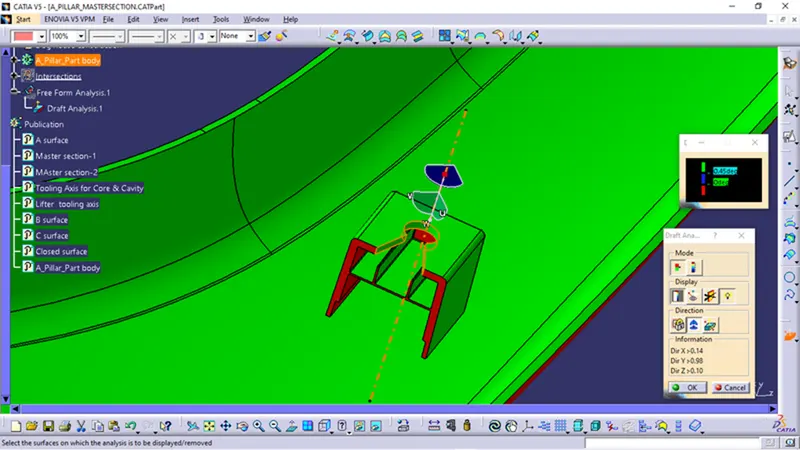
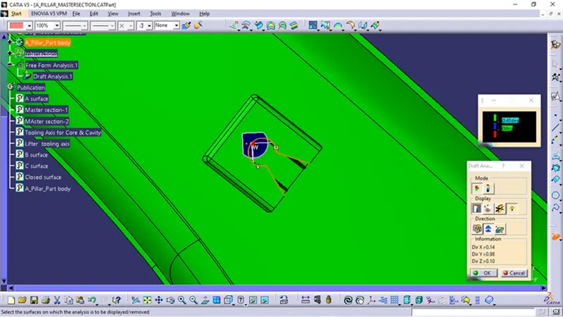
- Draft analysis along lifter tooling axis with 0.5degree draft.
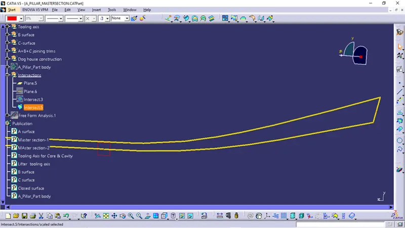
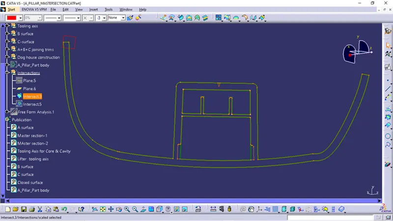
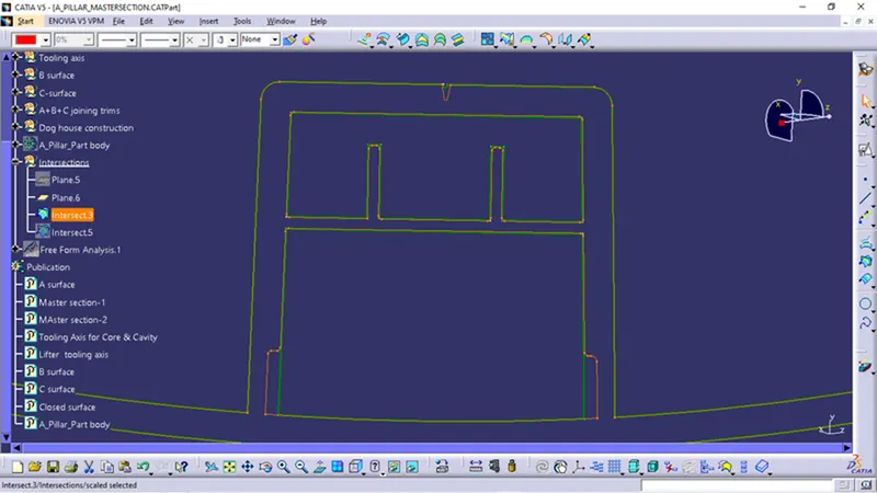
Master Sections Cross checking with our part model :
- Cross checking for each and every point in designing is a good quality.
- Here we are checking our part model with given master sections.
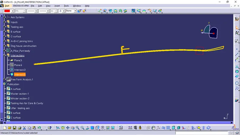
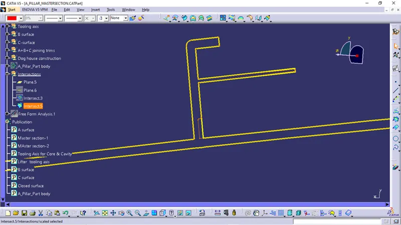
- This can be done by using Intersection feature in Generative Shape Design workbench
- For that we need to create a plane along master section
- Now intersect our part model with the plane
- The thick yellow line and Thcik green line is master section and Lite red line is our intersection curve of our part model.
- In some areas it seems to be not matching thats because we add engineering features to out part model like design considerations and drafts etc.
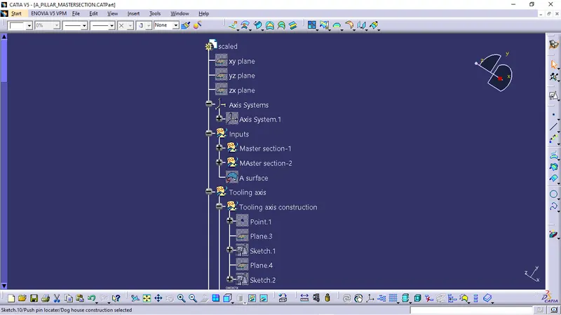
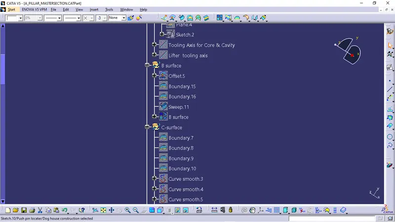
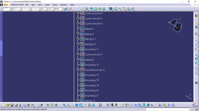
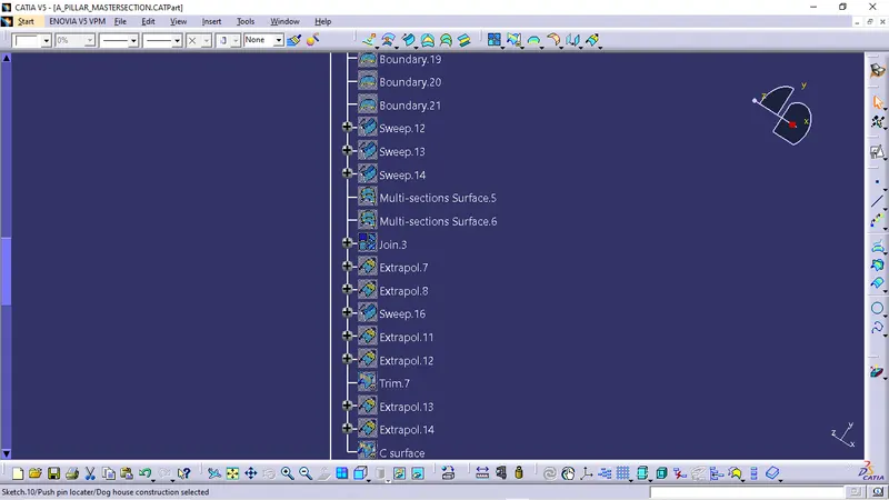
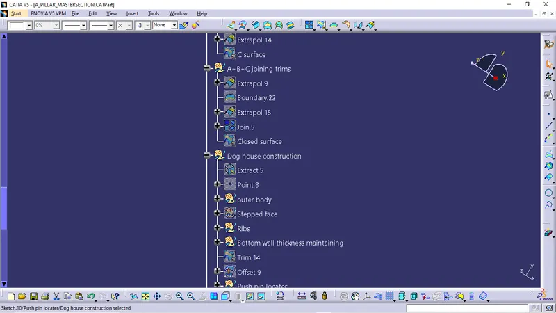
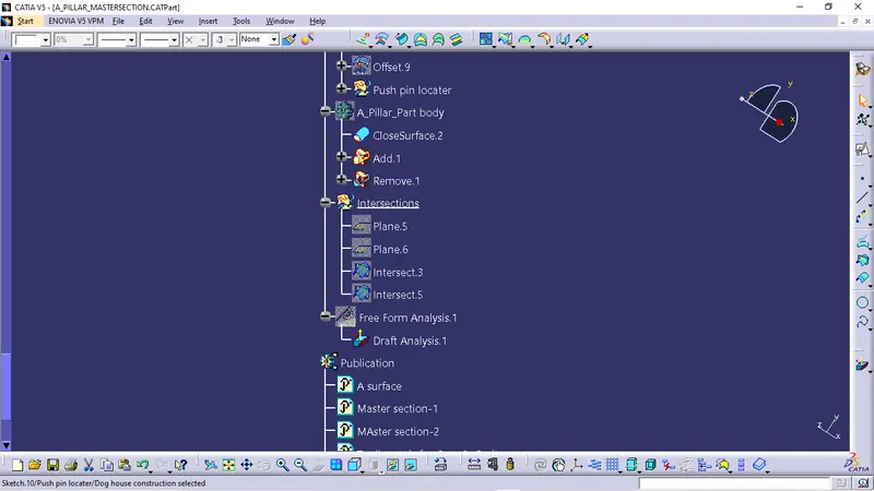
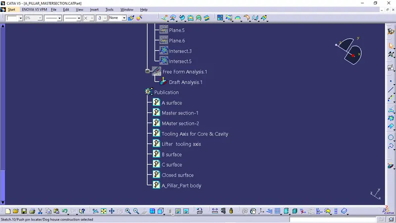
Tree Structure :