Week 9 - Project - A pillar Design with Master Section
'Design & Analysis of A pillar Design with Master Section'
Input:
Class A surface: It is one of the most important input in automobile industry specially in plastic design and is also one of the stages of design life cycle usually class A surfaces are created in Autodesk Alias for sketching concept modelling and visualization and then New product development in cad software is carried out. Class A is an aesthetic surface developed by a styler.
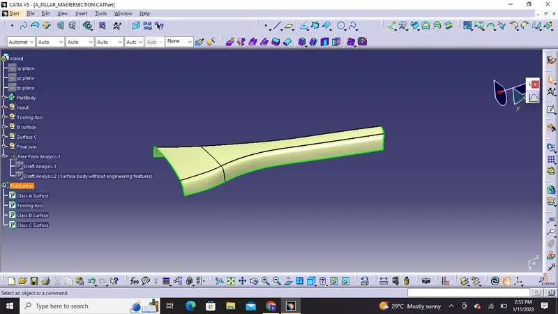
Class A Surface
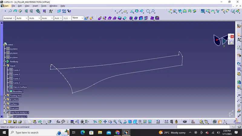
we will check the class A surface by putting boundary command on it and check for any irregularities so as to ensure that class A surface given is of good quality .
Class B Surface: B surface is the surface which gives us thickness from the class A surface, Class B is the engineering surface as all the engineering features like ribs ,boss etc are made on this surface.
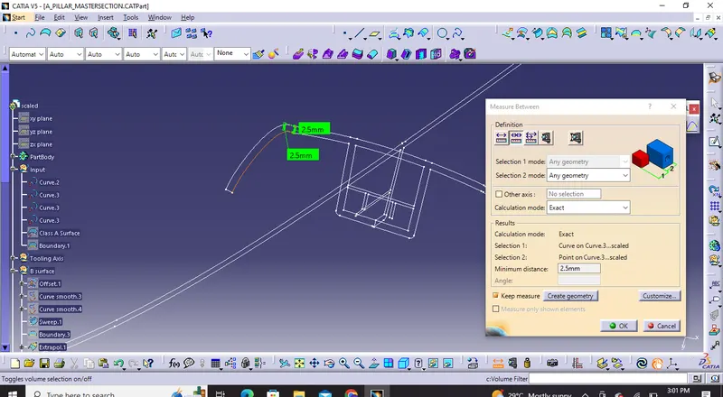
With Master section we can measure the thickness of the components to make sure how much we have to offset or provide thickness.
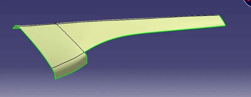
There were some surfaces on sides which vanished after offsetting ( 2.5mm as per master section) the class A surface so I used Sweep,Split,multisections, extrapolate and trims to form class B surface.
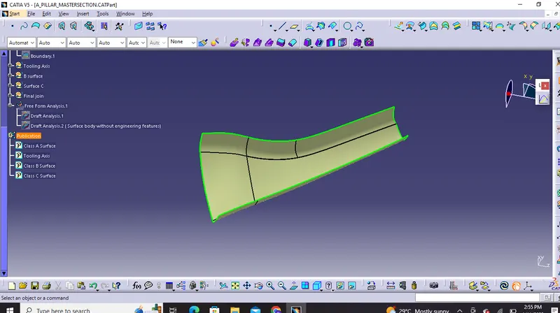
Class B Surface with no patches or discontinued body
Class C Surface : C surface is the surface which connects A and B along the tooling direction and is called Class C surface. We can make class C surface using extract,sweep, trims,extrapolate etc.
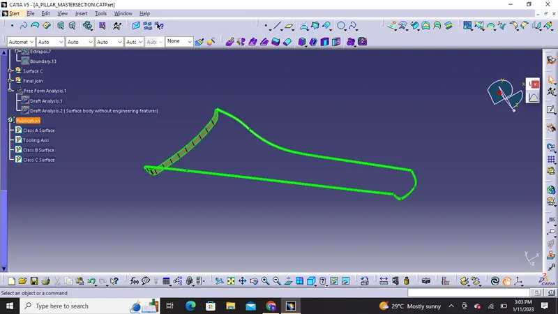
Class C Surface made from Class A surface
Final Trims : Class A and Class C surfaces are joined and are trimmed against extrapolated B surface giving us the final surface body with closed boundry.
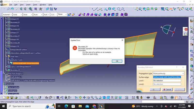
Surface boundary with closed boundary without engineering features
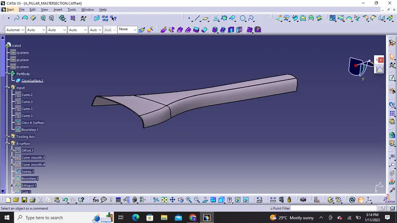
Part body with closed surface without engineering features
Tooling Axis : It is the direction in which the mold or core cavity opens to eject the part.There are multiple methods for creation of tooling axis.
we can extract a surface from class A and create a point in the middle of that surface by using point command and create a line normal to that surface at that point through the y axis and we will perform draft analysis to check whether the created tooling axis is in the correct position or not , If in the draft analysis both the surface sides are in green color our position is correct.
or we can also follow bisection method through intersection.We can make tooling axis by center point on the model and using intersection we can create bisecting lines with master sections and bisecting line will bisect the two lines if they are perpendicular and will show some error if they are parallel this will decide that whether the surface is toolable or not and then perform draft analysis on it as we performed on previous projects.
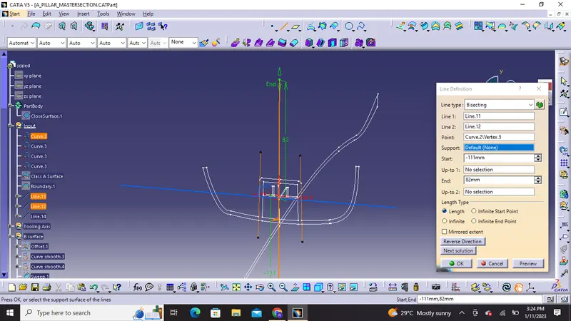
But for Tooling axis creation in complex and large parts like A pillars, door trim ,bumpers,etc we can also draw tooling axis in the centre of gravity point using inertia method as The centre of gravity is a point in an object where the distribution of weight is equal in all directions and this point will be suitable for the direction of extraction of component very easily. Then we can view the component in all directions and for this bumper x direction will be best for creation of tooling axis using the centre of gravity point
Steps for inertia method are as follows:
1) We will click on measure inertia button which is beside measure item .
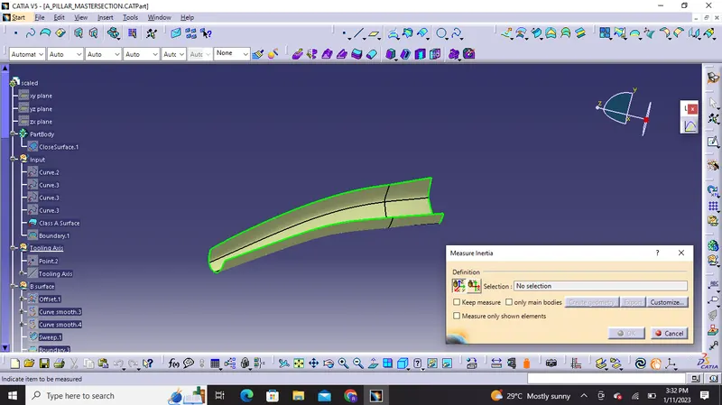
2) After selecting Class A surface we will next click on create geometry
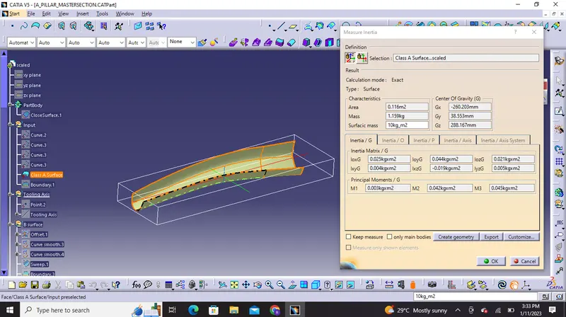
3) Furthermore we will click on non associative geometry and select centre of gravity and press ok
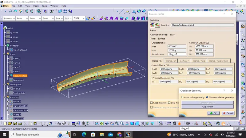
4) The inertia point will be created.We will select a line and select point and direction in which inertia point and Y direction is choosed for final creation of tooling axis
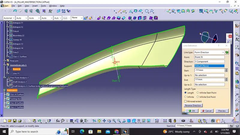
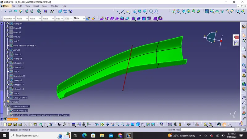
Final Tooling Axis
Draft Analysis:
Draft is the angle in which the part is tapered to allow it to release from the mold properly and as the part is cooled it has a tendency to shrink towards the core side of the mold due to this we need to add draft angles.Nominal draft angles is usually around 3 degrees and more than 3 degrees can also be manufactured like 5 degrees but it will unecessarily increase the costing of manufacturing and final product.
Procedure used for draft analysis in Catia cad software:
1) In display frame first we need to change it to material mode
2) Click on insert then analysis and select feature draft analysis
3) Then we will click on compass and and align it with tooling direction.
4) Then we will click on the lock symbol and then click on the surface of the part the colour will change
5) Different color codes are identified and there we can apply draft angle which will reflect us minimum draft angle in green color.
6) We can also have running point analysis on different regions of the part body for permissible draft angle.
Draft Analysis on Class A Surface
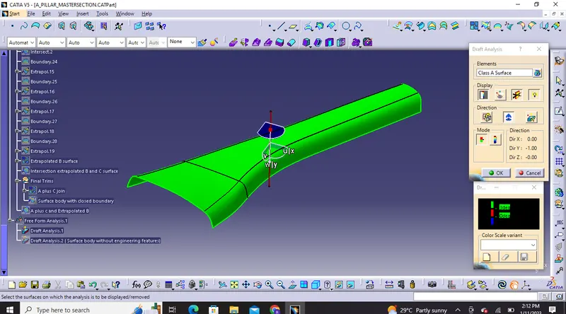
Minimum Draft angle 3 Degrees
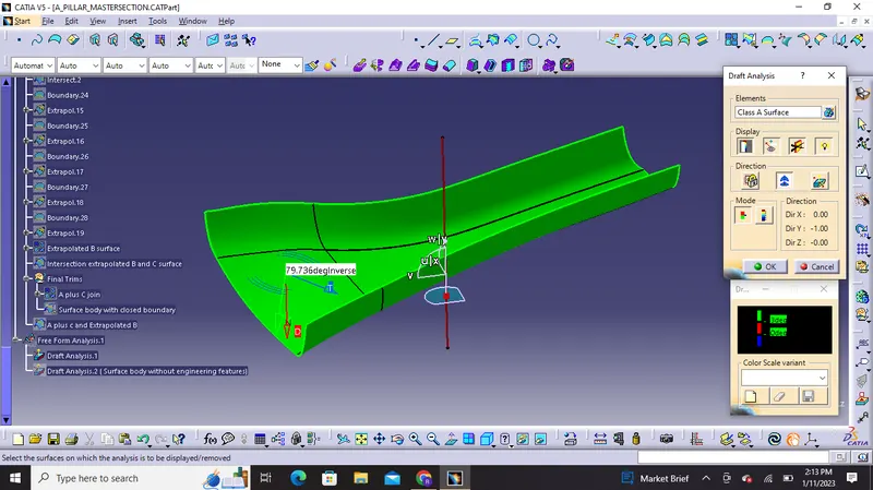
Running point Analysis on opposite side also clears the 3 degree draft which shows our tooling axis is correct.
Draft Analysis on A Pillar ( Surface body with closed boundary ) without engineering features
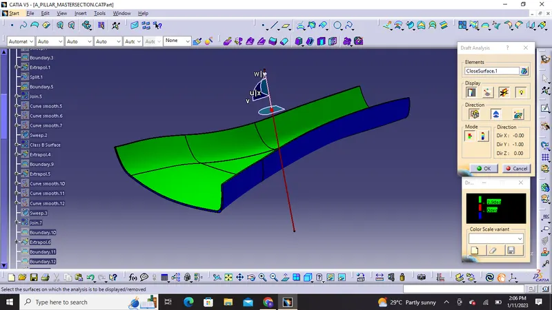
Minimum draft of 2.9 degrees
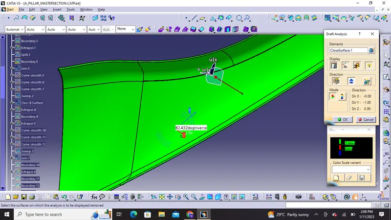
Running point Analysis
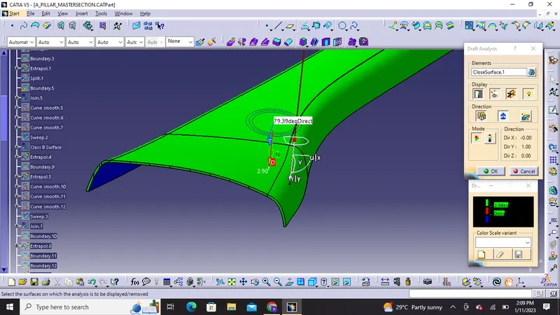
Inversing draft shows top surface with cleared draft at 2.9 degrees
B Side Features:
Dog House :
Dog house is an engineering feature to avoid sink marks which is created on class A surface by screw boss or ribs on back of class A and also there will be length issues but with dog houses we can increase height of that area by giving cross section along B and can still have engineering feature on it.
Design Rule for Dog house are as follows:
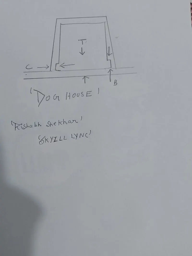
1) Dog house wall thickness at intersection of part wall (C) should be 40% or less than the main wall thickness.
Suppose the main wall thickness of the component is 2.5mm then 40% of it will be [0.4x 2.5= 1mm)
C is where the doghouse contacts the backside of the surface.
2) The height of the (B) should be between 3.0 to 6.0 mm in my design i considered it around 3mm.
3) The minimum dog house width should be atleast 12mm due to molding feature.
4) Minimum draft for dog house is around 1.5degrees but if a slide is being considered this requirement can change to 3 degrees minimum.
Ribs: They provide a means to economical stiffness and strength in molded parts wthout increasing overall thickness. They also facilitate some of the features like:
- Locating and arresting components of an assembly
- To provide alignment in mating parts
- It can also act as a stop or guides for mechanisms.
Proper rib design involves five main issues like:
- Thickness
- Height
- Quantity
- Location
- Manufacturability
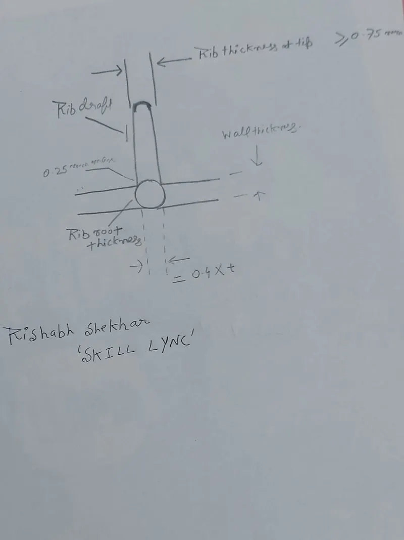
Calculations for Ribs :
1) Maximum thickness of ribs = 0.4 x thickness of component
In our Component the thickness is 2.5mm so max thickness of rib can be around 1 mm
2) Height of the ribs : It is 5 times the thickness of the component
3) Draft: 0.5 Degress of draft should be given on the ribs
4) Rib Thickness at tip should be greater than or equal to (>0.75mm)
5) Edge fillet : 0.25mm on ribs face or edge
6) Rib root thickness should be be 1.4 times thickness of component and maximum of around 4.2mm
7) Spacing between ribs can be according to 3: 1 ratio height to width suppose height of rib is 12.5 and space between ribs is x which is equal to 3:1 ratio then 12.5/x = 3:1 which is equal to x=4.1mm. Although spacing can be altered as per requirement only thing is that it should be manufacturable.
But certain rules can also be altered as per master sections and requirements of the customer for the component.
Draft Analysis on B Side Features
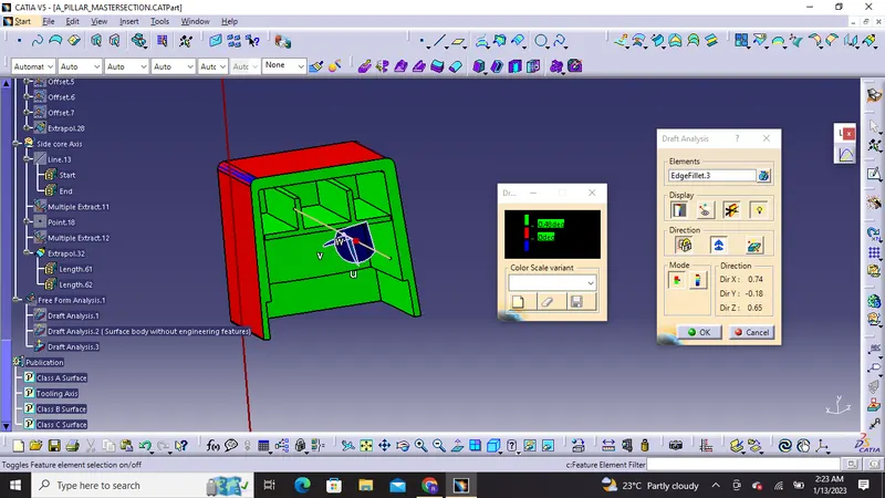 Inner Area of Dog house is cleared at 0.48 Degree of draft using side core axis
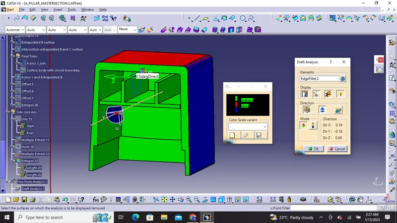
Running Point Analysis on inner side showing 0.5 degree of draft on Ribs
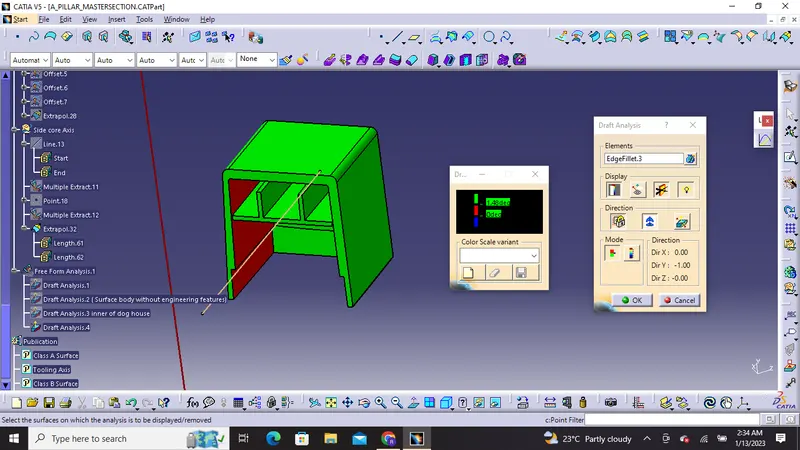
Outer Area of Dog house is cleared at 1.48 Degrees which is near to 1.5 degree of draft angle
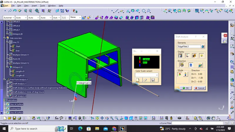
Running Point Analysis on outer Area showing 1.5 degrees of Draft
Draft Analysis On Final Component with Engineering features:
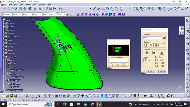
It is clearing Draft at 1.48 Degrees
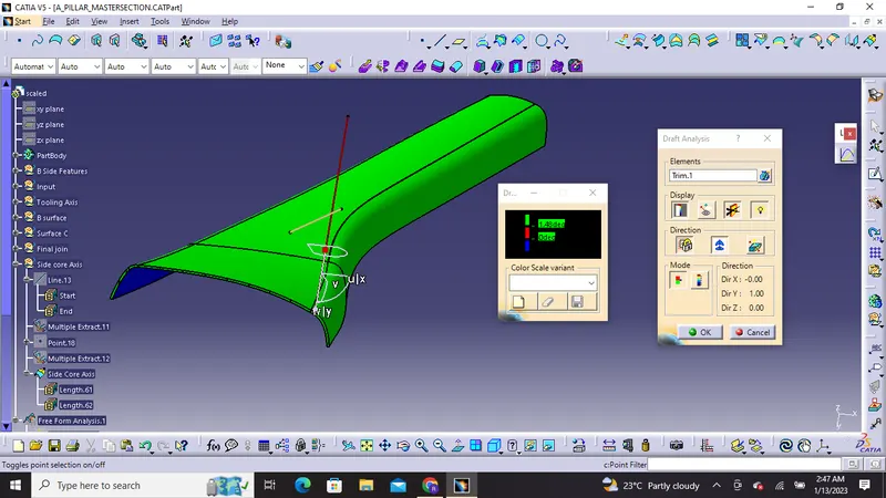
Inversing the Draft it is also clearing the top surface with 1.48 degrees

Draft analysis on inner side using side core axis after final assembly
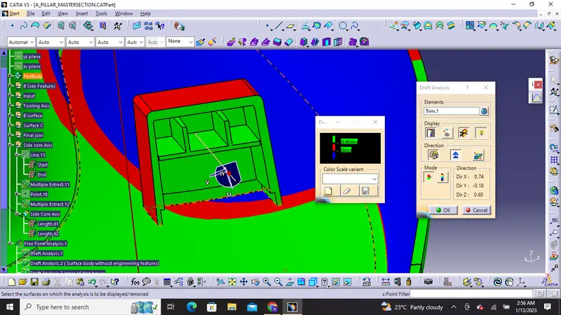
It is clearing the inner areas of Dog house at 0.48 degrees using side core axis
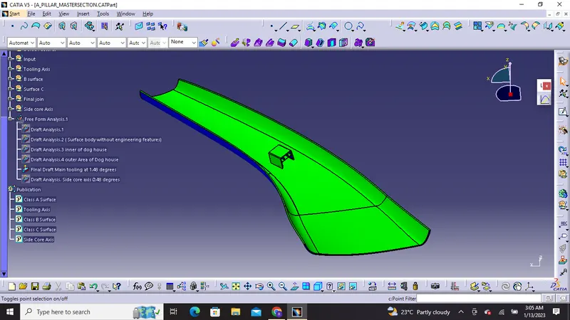
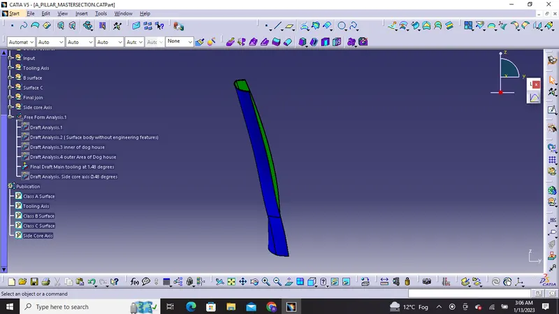
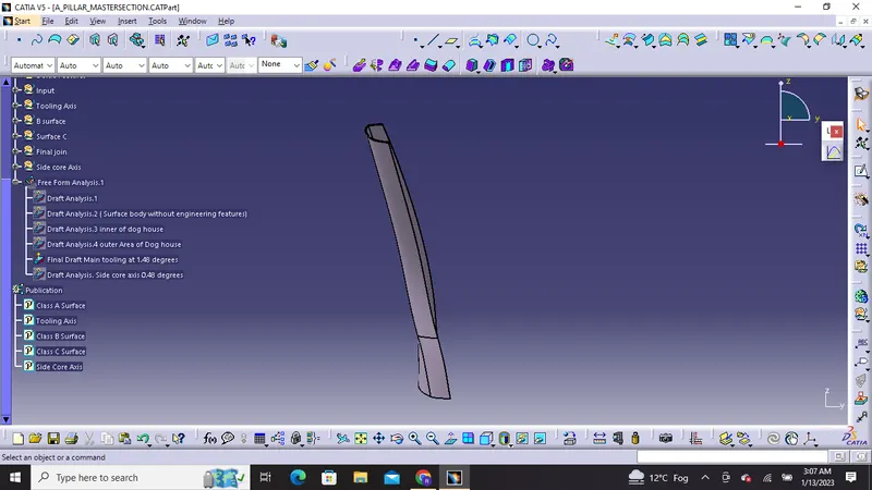
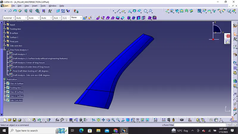
Different views of the solid body in various orientations :
1) Isometric View:

2) Front view
3) Side view
Left view
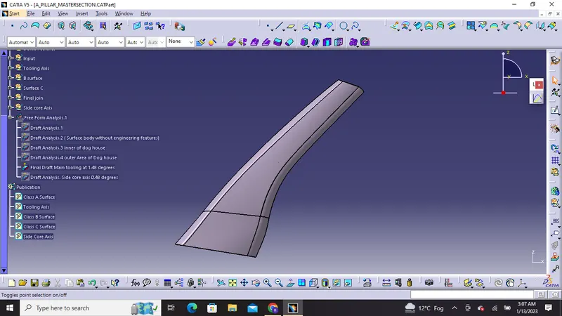
Right View
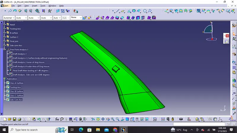
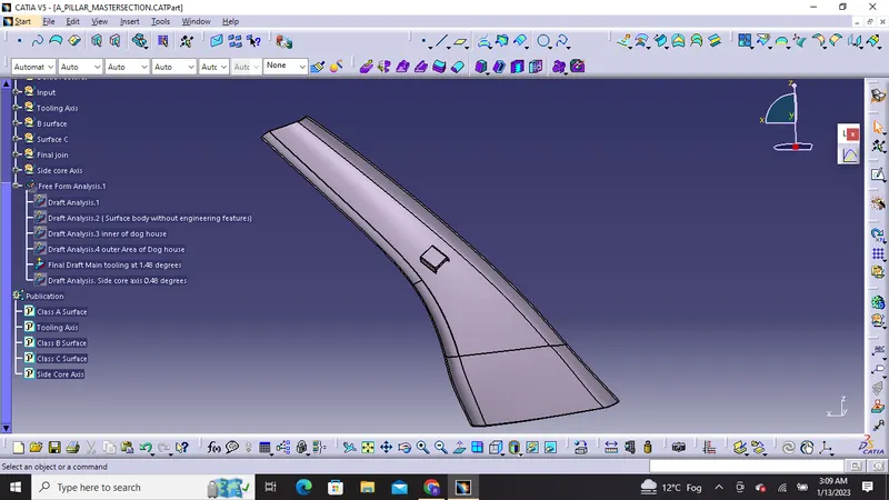
4) Top view
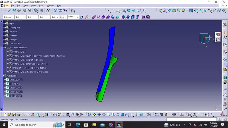
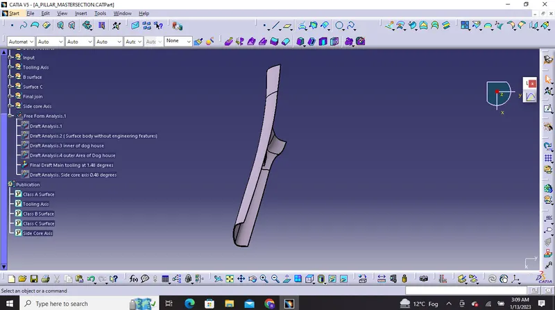
Output:
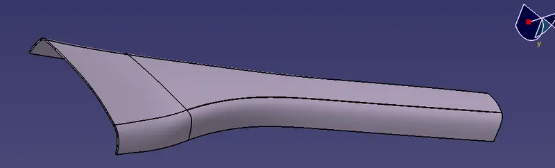
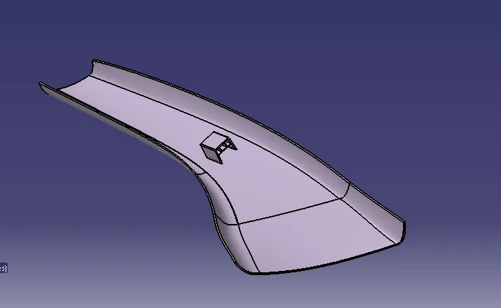
Please find the attached PPT and CAT File for your reference. Thank You!