DESIGNING A PILLAR USING MASTER SECTION
OBJECTIVES
- To improvise the Class A surface by resolving bad patches and adding flanges to it.
- To create A pillar solid model with the help of improvised class A surface.
- To create B side features for the A Pillar using the master section given to us as an input.
- To create main and side core tooling axis for A pillar and its B side features.
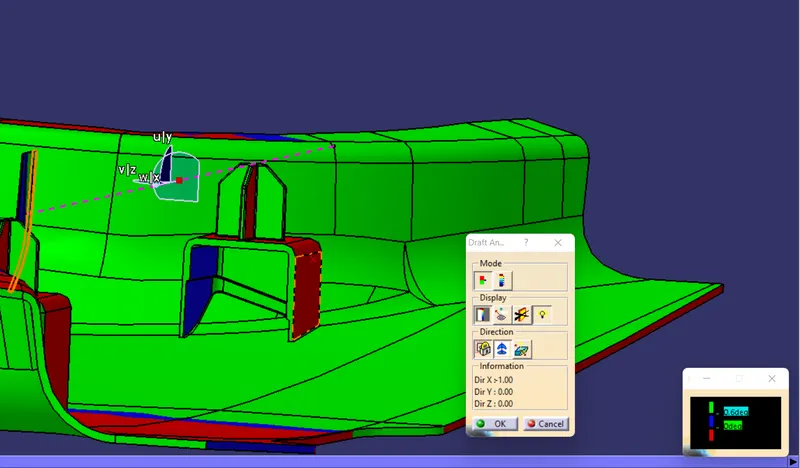
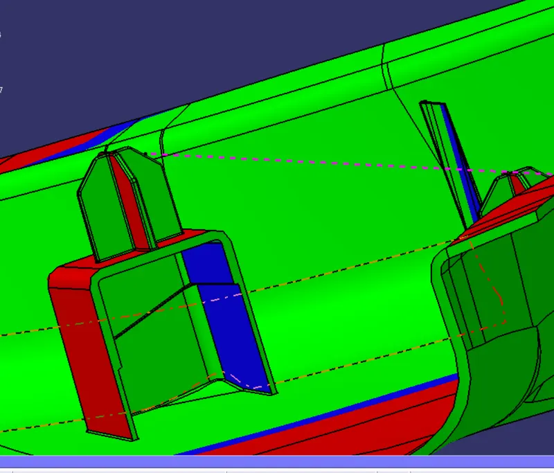
- To do the draft analysis of the overall model of the A pillar i.e including B side features.
INTRODUCTION
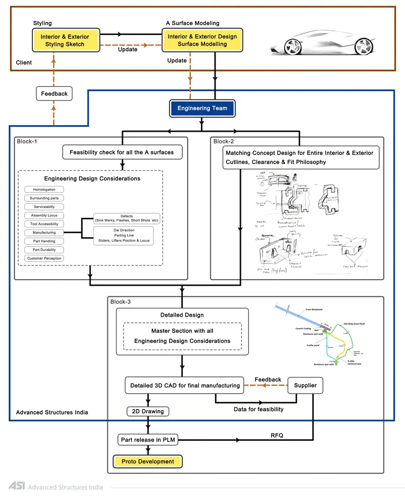
MASTER SECTION: Master sections development takes place during feasibility check and concept validation stages of the product life cycle. These are typically the guides for design requirements and which decides the component packaging after the development of the concept design, i.e class A surfaces.
Master section helps us to decide the feasibility of the concept design, the clearances, the packaging and the fixation strategy of a component before converting the concept design into a solid 3D engineering design.
During the period of vehicle concept design the evaluation of the master section performance depends mainly on the reference vehicle data and experience of structure design engineer.
Tooling Direction for Plastic Part
Overview:-
- Tooling direction is main consideration for plastic part and mold parts because it defines movement of mold part and possibility of plastic part to come-out from mold part (Core and Cavity).
Tooling Direction:-
- In Molding machine arrangement is given to open the mold along a direction which is known as Tooling Direction.
- In other words. The mold is built from two separate halves (Core and Cavity) and tooling direction basically define the direction of mold pulls apart.
- Tooling direction is known as primary direction.
The Tooling Direction is basically the direction that the mold pulls apart. The mold is built in two separate pieces, basically. You have a Cavity side and you have the Core side. The Core pulls apart from the Cavity and that's the Dyeline or the Tooling Direction.
Draft Analysis
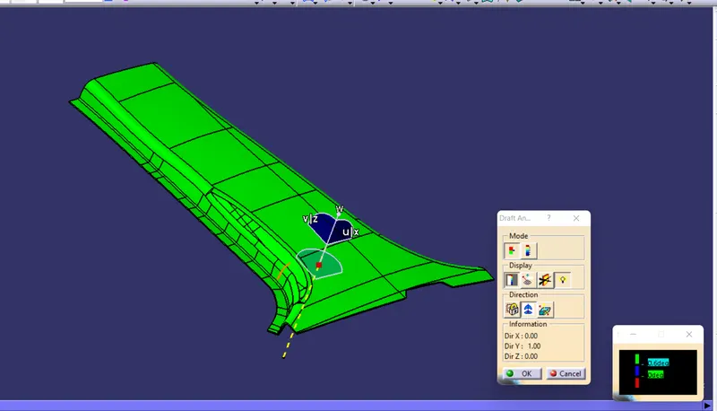
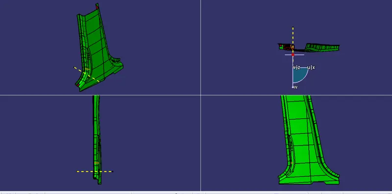
Draft analysis check to make sure that the class A surface is meeting the draft required the draft required along the tooling direction.
- The draft analysis technique is used to analyze whether our part model created in CAD is manufacturable based on the draft condition applied. Here the part should get easily removed from the panel dies (in case of Sheet metal part) or Mold (in case of plastic).
- No parts can be ejected from the tool if it is having a straight 90-degree profile from its base surface. A small draft angle is provided to each and every area of the component in order to get easy removal of the component from the tool.
- Here we are providing a direction in which components should eject in order to get easy removal of components from the tool. In other words, it also lets us know whether the model is having a draft angle and how much is the draft angle from the tool direction.
The Types of Components for Draft Analysis
- Draft analysis is performed on the components where the ejection of materials happens after the material is made inside the tools. In the case of Automotive Sheet Metal manufacturing, the blank sheet after turning into automotive panels like Hood, Fender, Roof, Side Doors, Back Doors etc. need to be removed from Panel Dies. If a considerable amount of draft angle is not provided, the removal of components from the tool will be difficult. It’s the same in the case of mold(plastic component) after getting filled inside the core and cavity, it needs to get ejected easily with the help of ejectors.
DESIGNING METHODOLOGY:
IMPROVING THE CLASS A SURFACE
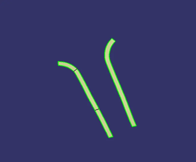
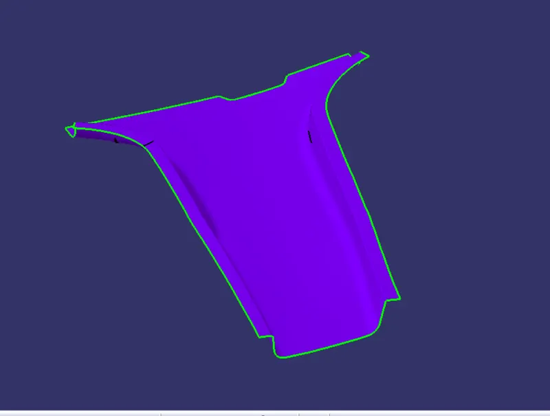
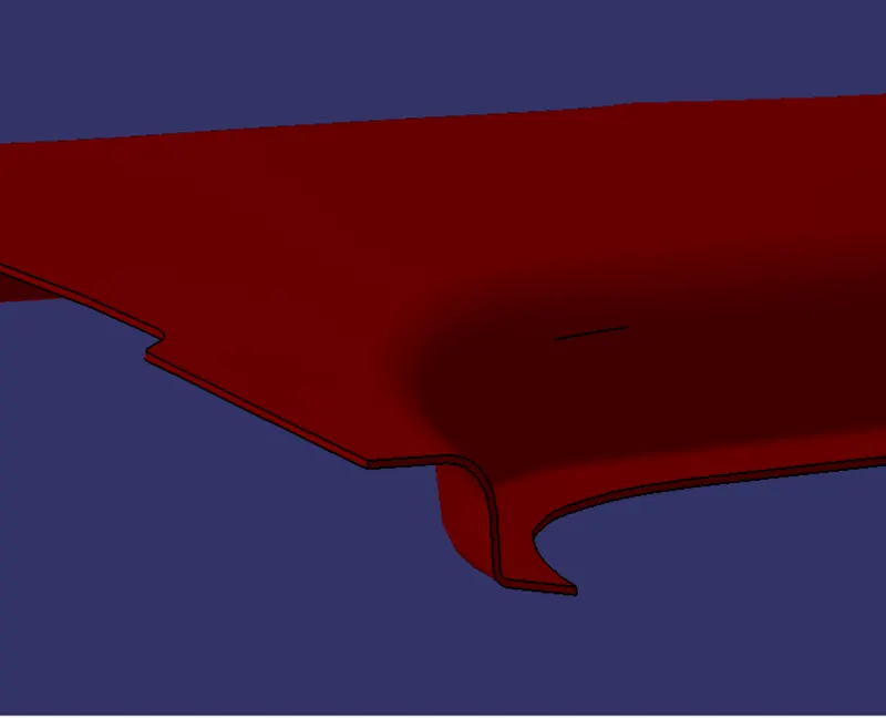
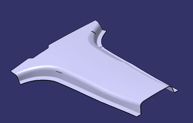
- The given class A surface is not a proper surface because it is lacking the side flanges so first thing that we have to do is to create the flanges on both the sides of the class A surface.
- For creating flanges we will first extract the side edges of A surface and the surfaces touching these edges.
- Finally we'll apply the sweep command using the "with reference to the surface" option and join the resulting edges with A surface using trim command.
- Make sure that the resulting flanges are properly oriented according to the master section.
CLASS B SURFACE CREATION
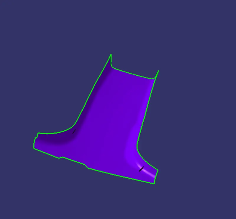
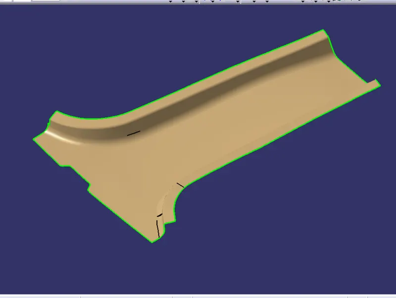
We need a thickness of 2.5mm for the A PILLAR so in order to create the class B surface we'll give an offset value of 2.5 mm to improvised class A surface.After applying the offset command we'll see some of the patches of the resulting surface are not generating so we have to recreate those patches by using multi-section surface command.On joining the recreated patches with the offseted surface we'll get the class B surface.
CLASS C SURFACE CREATION
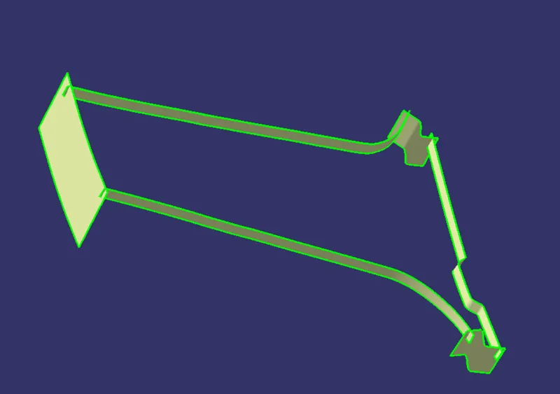
Extract the side edges, front edges and rear edges of the improved class A surface and use sweep command using "with refrence to draft" option and make the draft angle equal to 3 degrees.For the rest of the edges use multi-section surfaces command to make surfaces inline with the major surfaces created through sweep. all the surfaces together using join command.
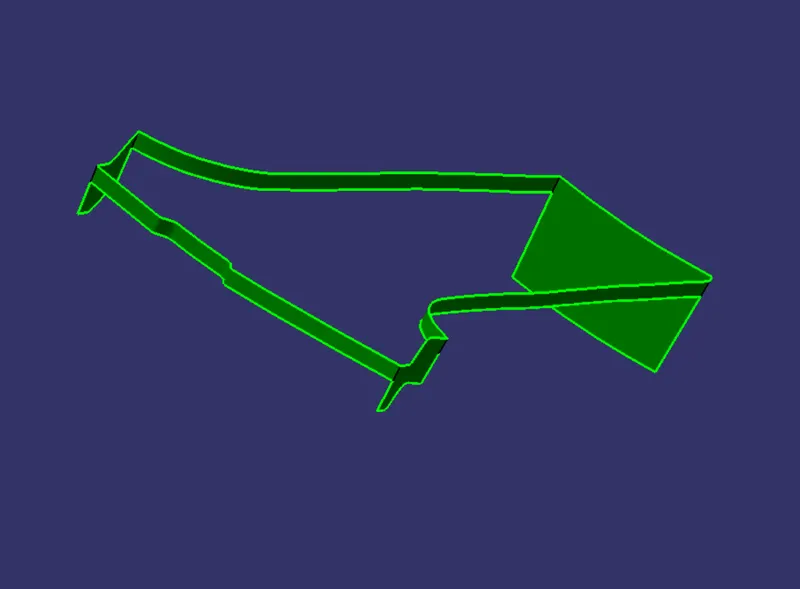
SOLID BODY CREATION OF THE A PILLAR
Using the Trim command join the class A surface with class C surface.Trim the resulting Trimmed surface with class C surface.The resulting trim we'll get is the closed shell body of A pillar.Finally use closed surface command in the part design workbench which would lead the shell body into a part body.
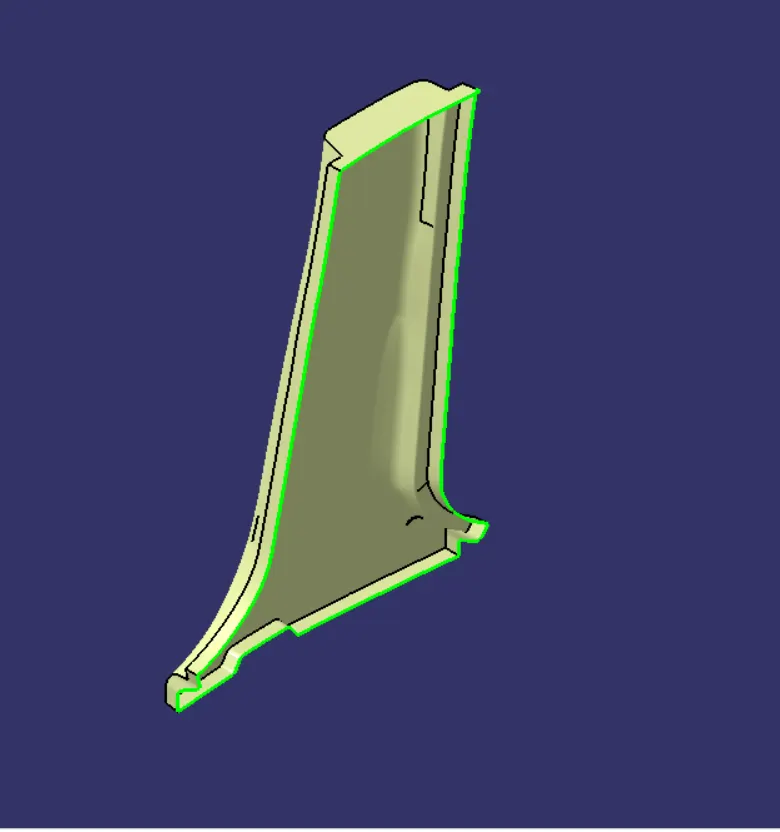
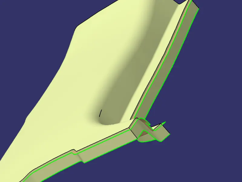
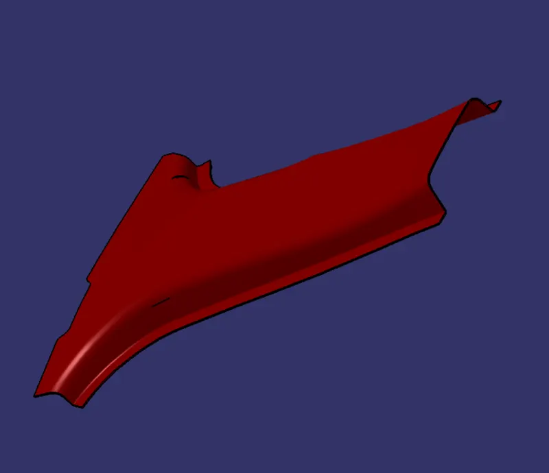
CREATION OF MAIN AND SIDE CORE TOOLING AXIS
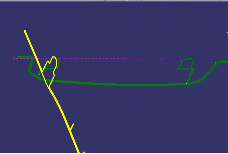
Apart from A surface and C surfaces we also need to consider the B side attachment features in order to create the tooling axis because all the attachment features have a large number of surfaces parallel to the tooling direction.For creating the tooling we can take reference from the master sections of the B side features and create tooling axis accordingly as shown in the figures below.
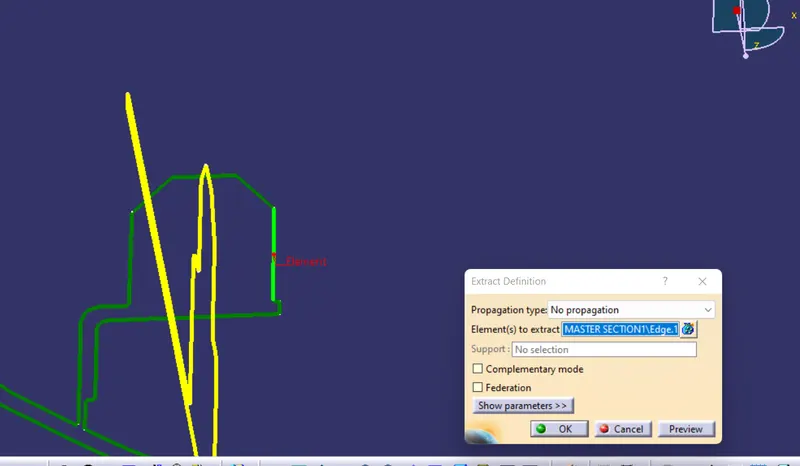
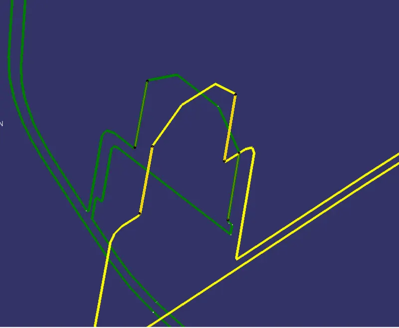
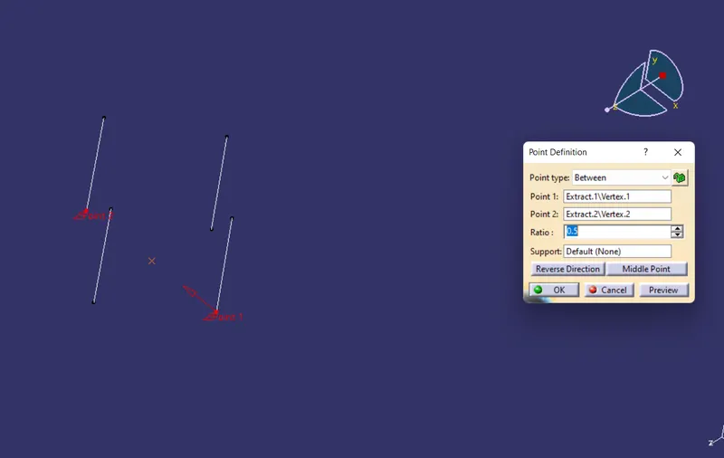
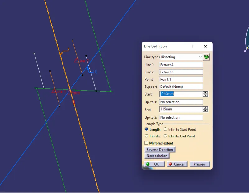
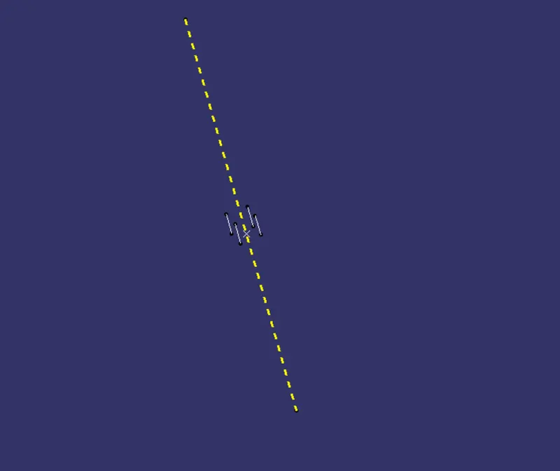
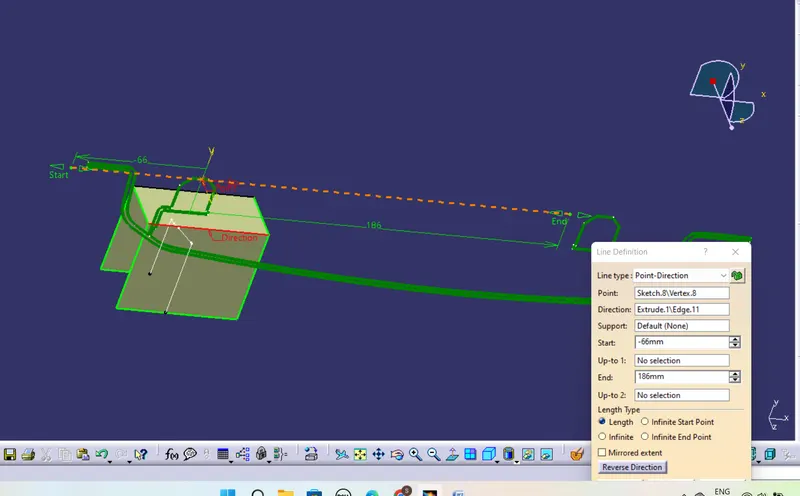
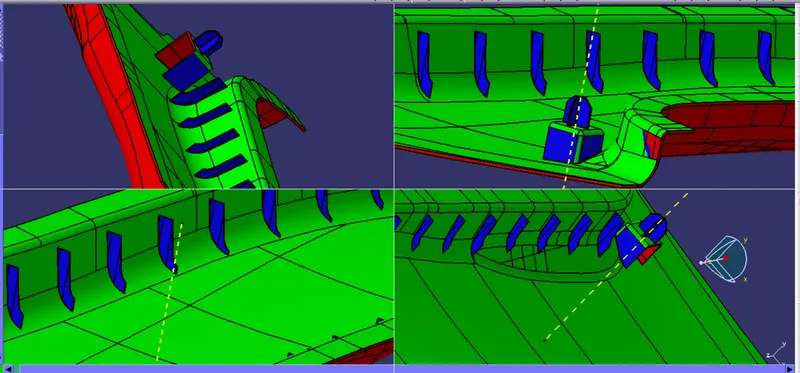
There are some of the attachment features like doghouse that needed a side core during moulding operation so for such B side features we have to create a side core tooling axis.
For the creation of side core tooling axis again we can take refrences from the master sections of the A pillar. This is shown in the figures below.
CREATION OF B SIDE FEATURES
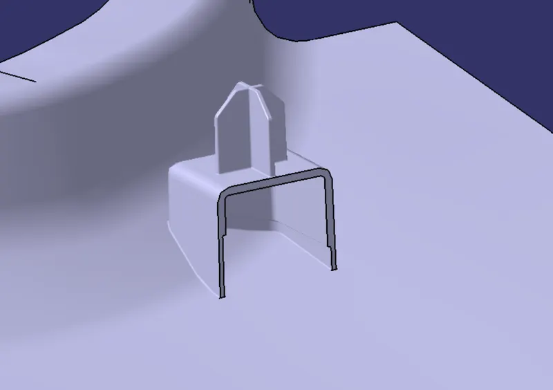
DOGHOUSE:
- Dog house are basically used to avoid sink marks on the A surfaces, specially at those regions where other attachment features like screw boss is attached, placing such features would add the thickness of the component at that particular region and this would leads to non uniform cooling of the molten platics during moulding resulting to shrinkage of the material from the outer side.
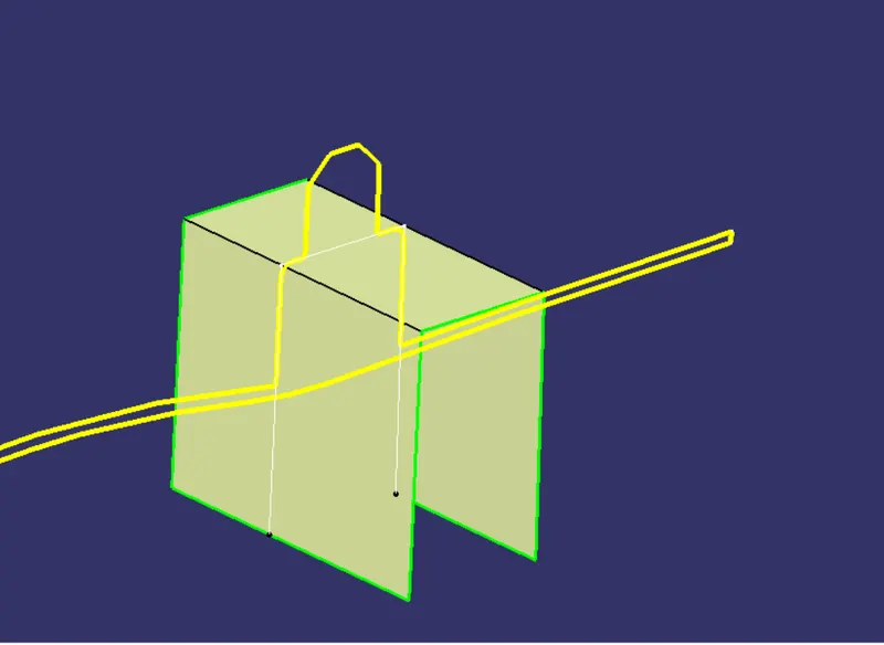
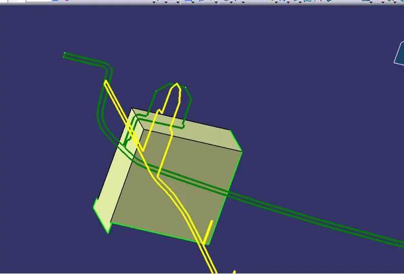
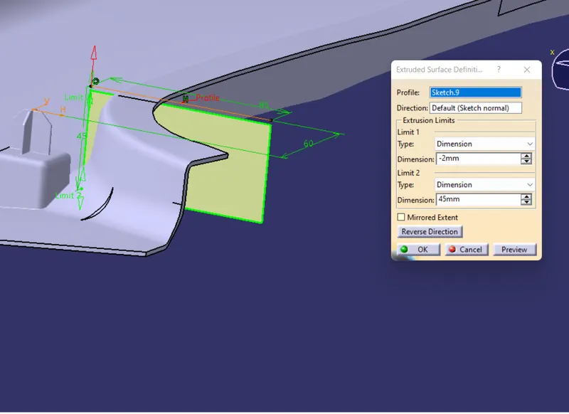
- The creation of doghouse is done completely using the master sections, first we create sketches by taking the refrences from the master section and then we applied the extrude command so that we would get the wall surfaces of the doghouse. make sure we extrude the sketches along the direction of side core tooling axis.
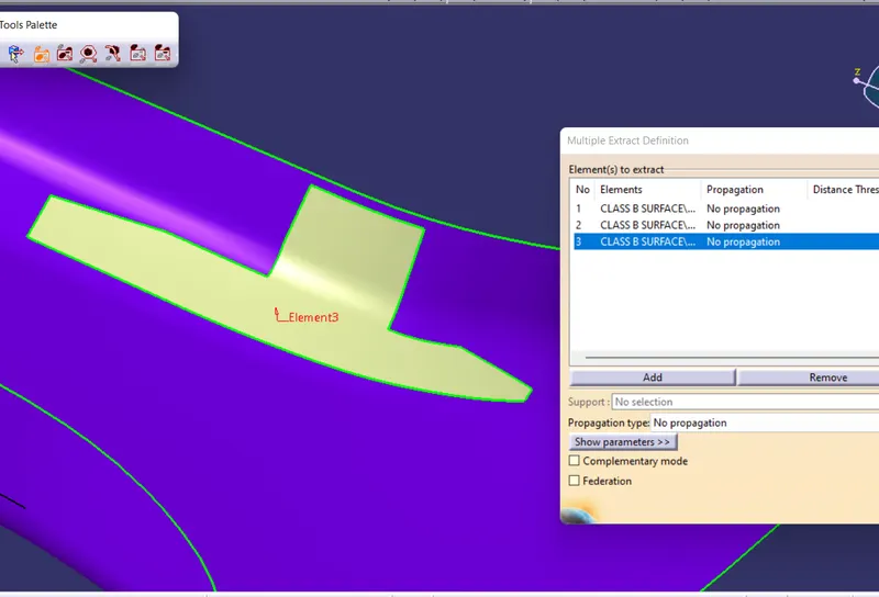
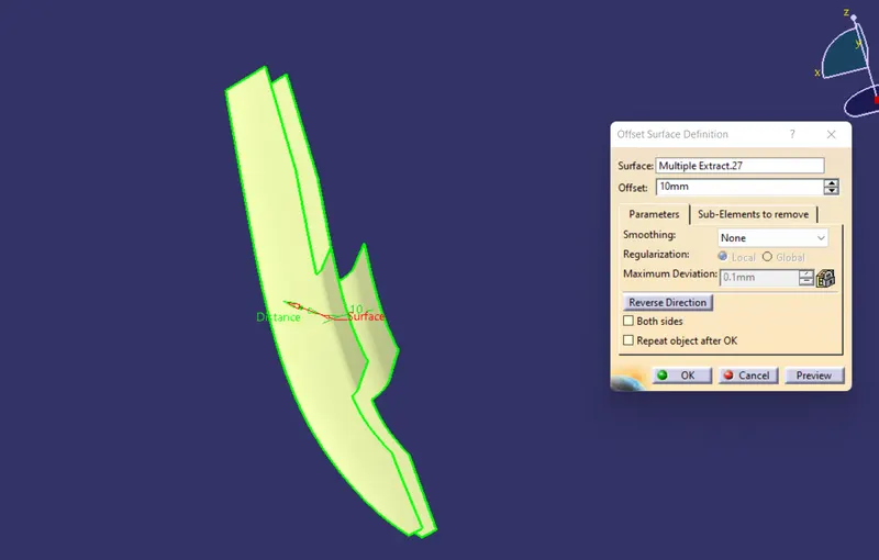
- similarly create the back surface of the doghouse by taking reference from the master section. After that we can use the trim command to give them a basic shape of the doghouse.
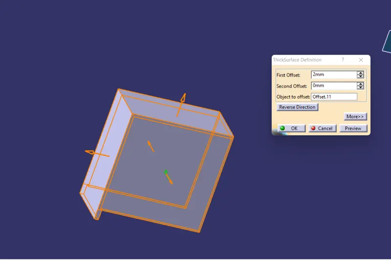
- Add material to the trimmed surface by using the thicken command in the part design workbench. Make sure we give thickness according to the doghouse master section.
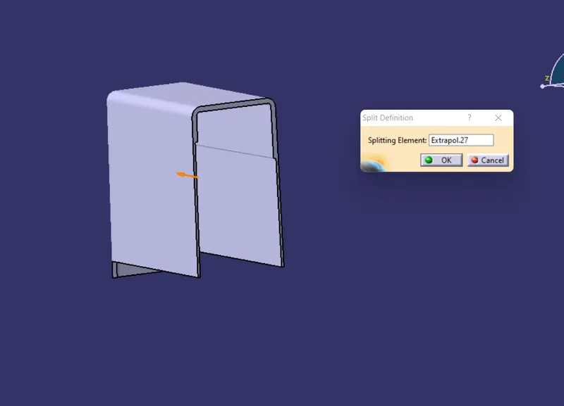
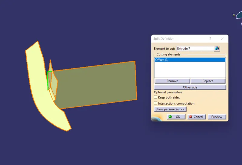
- We can further use split command to split the extra or unwanted material portion and give proper shape to the doghouse according to the master section. We also need to use the split command to reduce the thickness of the doghouse from the bottom i.e 3mm to 6mm upward from the bottom edge touching the B surface.
- The thickness to be reduced should be not less than 40% of the wall thickness.
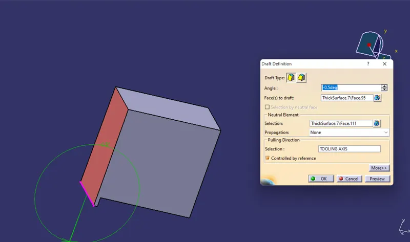
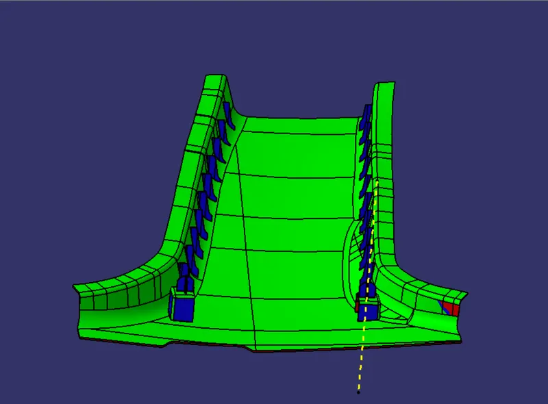
- Make sure that each face of the doghouse is drafted to a value of 5 degrees and these faces needs to be drafted by keeping mind their respective tooling axis along which they would be tooled.A minimum fillet value of 0.25mm is also required to all the edges.
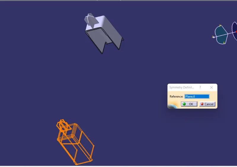
- For creating the second doghouse which is on the opposite side we will first create a copy of the existing doghouse by using the paste special option and then we will use the symmetry command to position the replica of the doghouse to the other side of the A pillar.
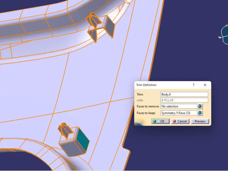
- Finally we will use the union trim boolean operation to join both the doghouses to the A pillar and trimming off the unwanted material at the same time.

FOURWAY LOCATOR:
The four way locator is used to arrest a number of degrees of freedom of the component when fitted to the its mating part. The four way locator is tight fitted into the counter part made on the mating part or component.
The process of designing the fourway locator would be same as that of the doghouse and we will again take the help of master section for creating it.
Draw the skect taking reference from the top view of both the master sections.
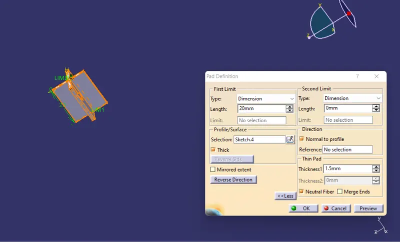
Use pad command to check on the thick checkbox to thicken the profile with 1.5mm thickness value. Make sure the pad length is long enough to cross the doghouse top wall.
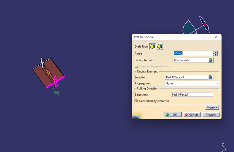
Give proper draft of 0.5 deg to all the faces, apply chamfer to the top corner of the fourway locator and apply fillet to all the edges of the locator.
Finally join the locator body with the doghouse body using boolean operations.
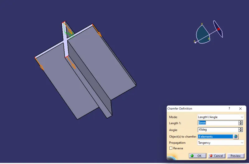
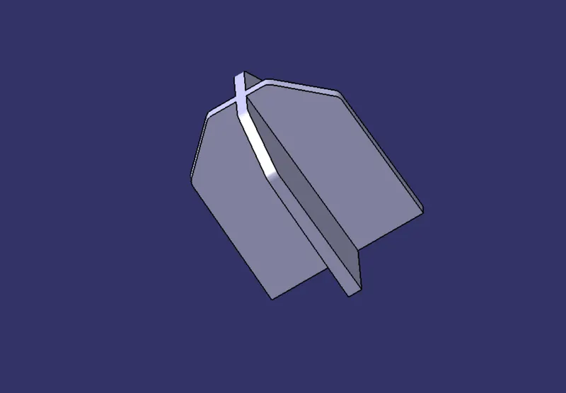
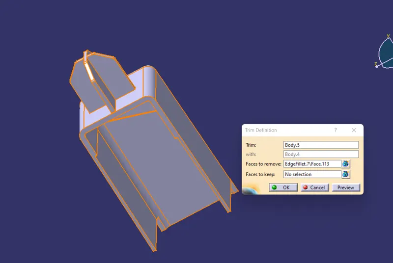
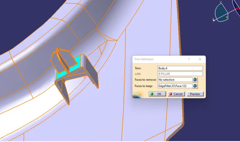
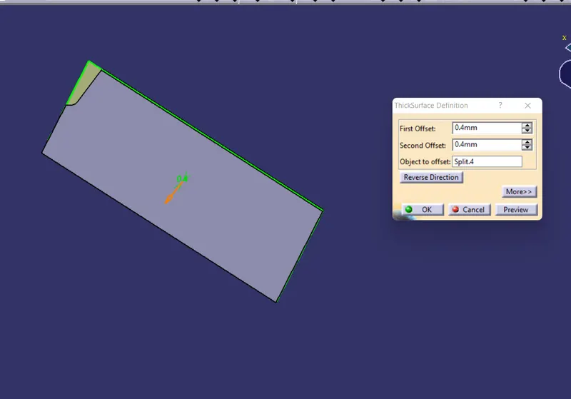
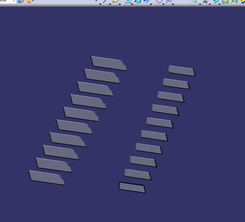
RIBS:Ribs are basically the supporting structures for the door trims or other plastic components having large surface area.The ribs acts as the back bone to the plastic component and provides support and increases the overall strength of the material, induction of ribs helps us to minimize the thickness of the component without compromising with its strength.
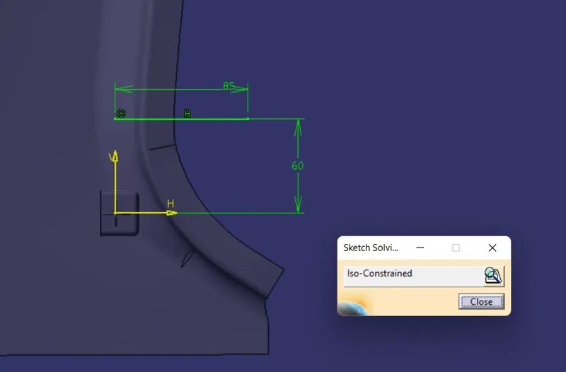
The rib is done here in a similar manner to those of the doghouse and fourway locator the extra thing we have applied in this case is the translation command to position the copies of the ribs to all along the A pillar with a gap of 50mm between each other.
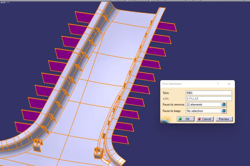
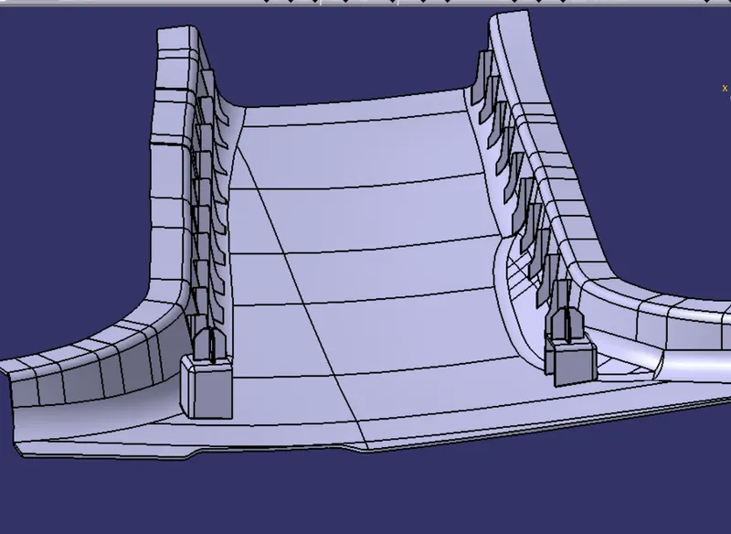
To join the ribs to A pillar we first assemble all the ribs into a single part body and then apply union trim boolean operation to join the resulting body with the A pillar while trimming off unwanted faces at the same time.
DRAFT ANALYSIS OF A PILLAR
DRAFT ANALYSIS FOR B-SIDE FEATURES
DRAFT ANALYSIS FOR SIDE CORE
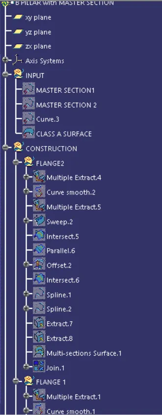
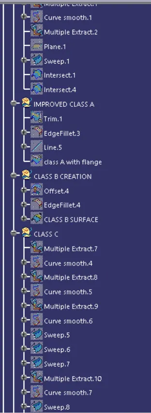
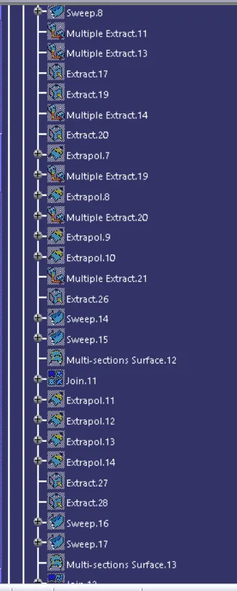
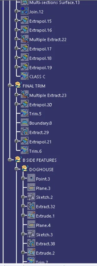
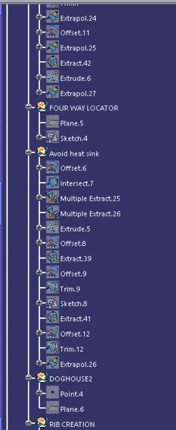
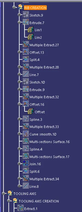
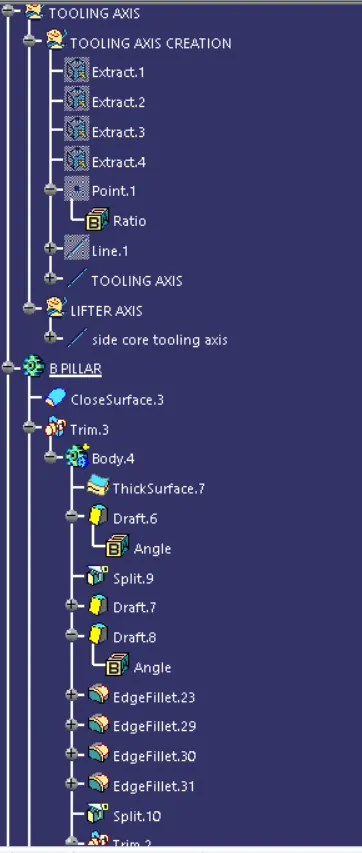
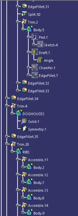
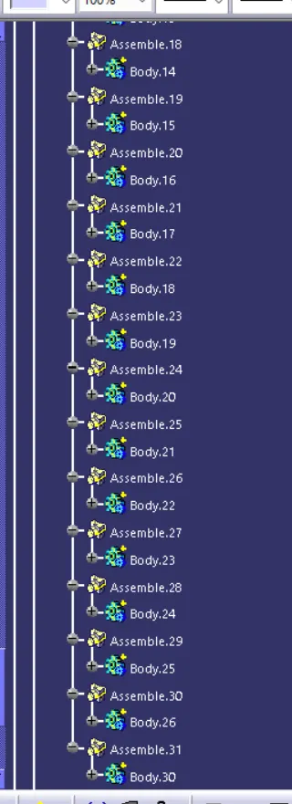
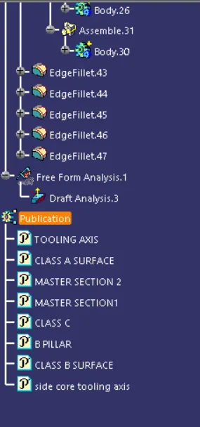
TREE STRUCTURE: