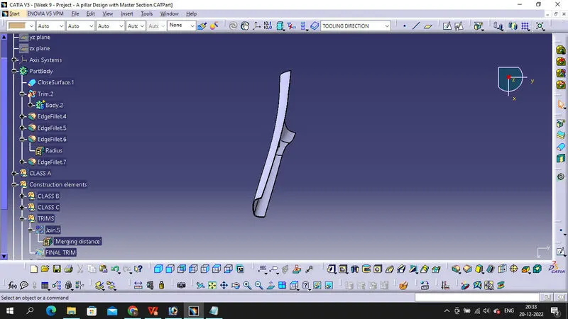
Week 9 - Project - A pillar Design with Master Section
MASTER SECTION: Master sections development takes place during feasibility check and concept validation stages of the product life cycle. These are typically the guides for design requirements and which decides the component packaging after the development of the concept design, i.e class A surfaces.
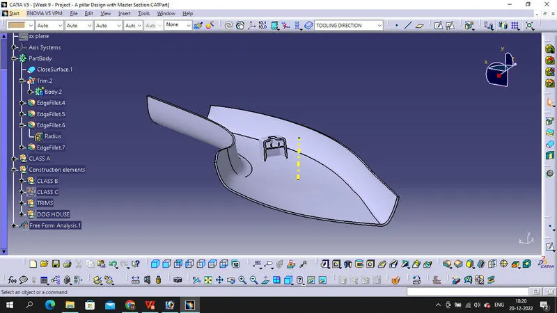
Master section helps us to decide the feasibility of the concept design, the clearances, the packaging and the fixation strategy of a component before converting the concept design into a solid 3D engineering design.
During the period of vehicle concept design the evaluation of the master section performance depends mainly on the reference vehicle data and experience of structure design engineer.
CLASS B SURFACE CREATION
We need a thickness of 2.5mm for the A PILLAR so in order to create the class B surface we'll give an offset value of 2.5 mm to improvised class A surface.
After applying the offset command we'll see some of the patches of the resulting surface are not generating so we have to recreate those patches by using multi-section surface command.
CLASS C SURFACE CREATION
Extract the side edges, front edges and rear edges of the improved class A surface and use sweep command using "with refrence to draft" option and make the draft angle equal to 3 degrees.
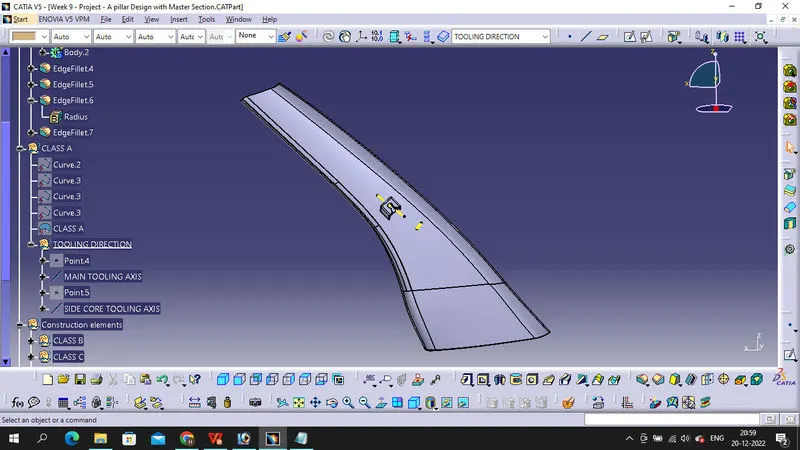
CREATION OF TOOLING AXIS
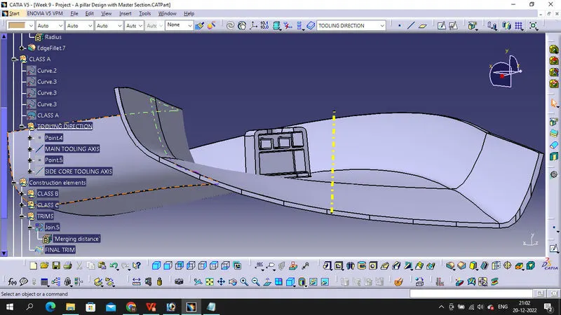
Apart from A surface and C surfaces we also need to consider the B side attachment features in order to create the tooling axis because all the attachment features have a large number of surfaces parallel to the tooling direction.
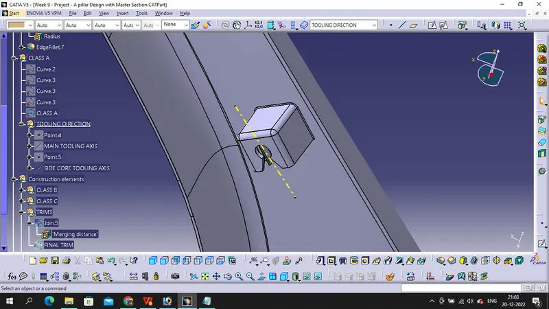
For creating the tooling we can take reference from the master sections of the B side features and create tooling axis accordingly as shown in the figures below.
Creation of B Side Features
DOGHOUSE: Dog house are basically used to avoid sink marks on the A surfaces, specially at those regions where other attachment features like screw boss is attached, placing such features would add the thickness of the component at that particular region and this would leads to non uniform cooling of the molten platics during moulding resulting to shrinkage of the material from the outer side.
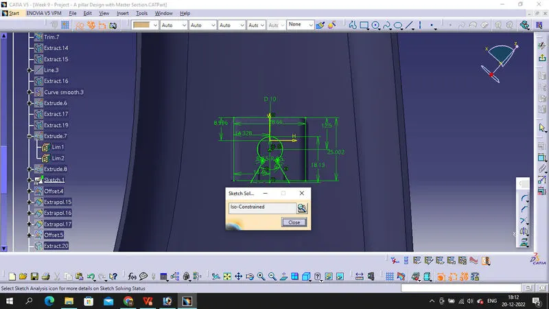
The creation of doghouse is done completely using the master sections, first we create sketches by taking the refrences from the master section and then we applied the extrude command so that we would get the wall surfaces of the doghouse. make sure we extrude the sketches along the direction of side core tooling axis.
DRAFT ANALYSIS
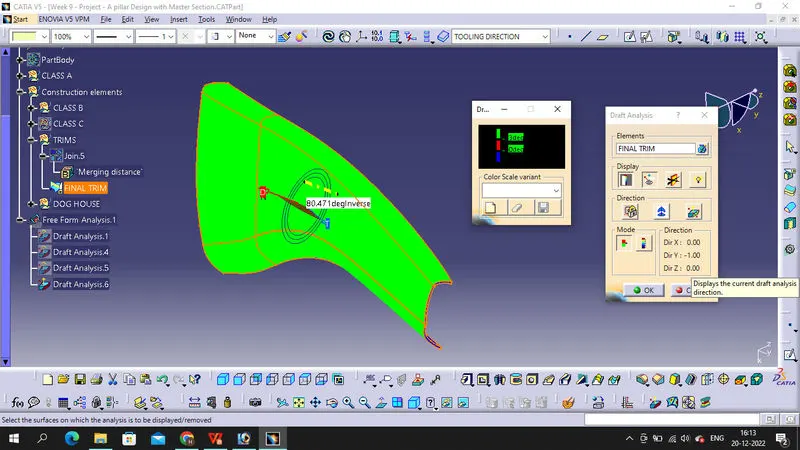
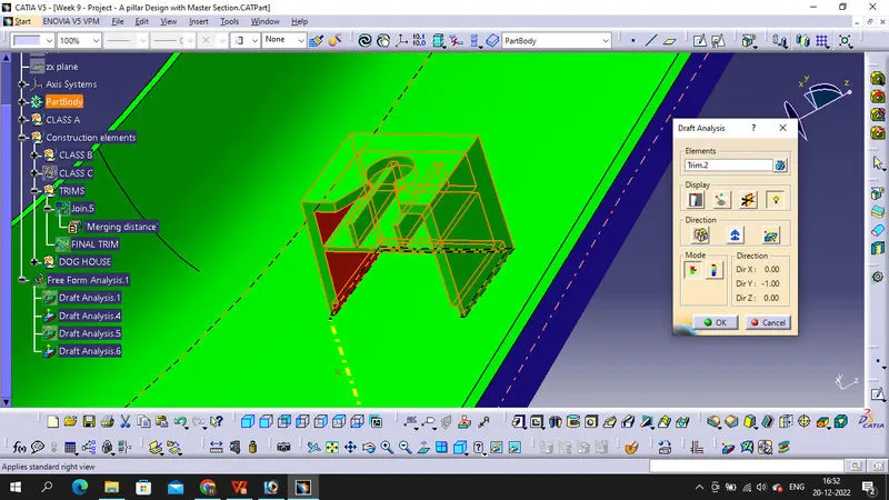
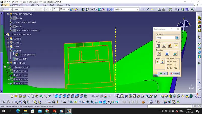
Do this draft analysis of given A Surface and check all face have 3 degree angle on both sides. after creating tooling axis and B, C Surface, creat final component do the draft analysis to it with main tooling axis, detail report is in PPT file, do draft analysis to dog house and edeges of the dog house, for edges draft angle is 0.5 degree. please check below attachment for Detail report of draft analysis.
Sketch View
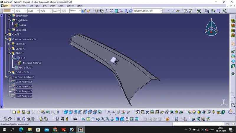
Isomatric View
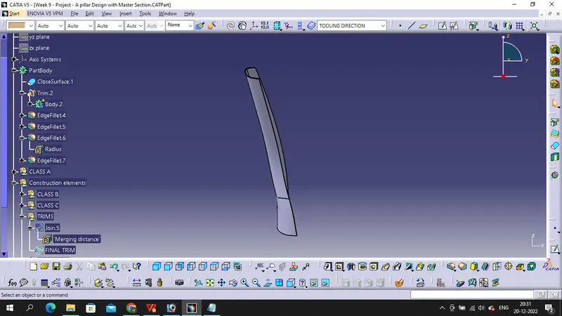
Front View
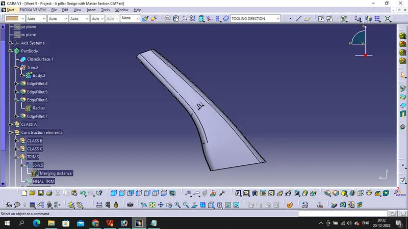
Side View
Top View