Week 9 - Project - A pillar Design with Master Section
AIM : The objective of this project to develop Closed Surface Model using Master Sections and to develop attachment features for Fixation of Parts by following OEM Design standards and procedures in CATIA SURFACE WORKBENCH and PART DESIGN.
OBJECTIVES :
- To improvise the Class A surface by resolving bad patches and adding flanges to it.
- To create A pillar solid model with the help of improvised class A surface.
- To create B side features for the A Pillar using the master section given to us as an input.
- To create main and side core tooling axis for A pillar and its B side features.
- To do the draft analysis of the overall model of the A pillar i.e including B side features.
INTRODUCTION :
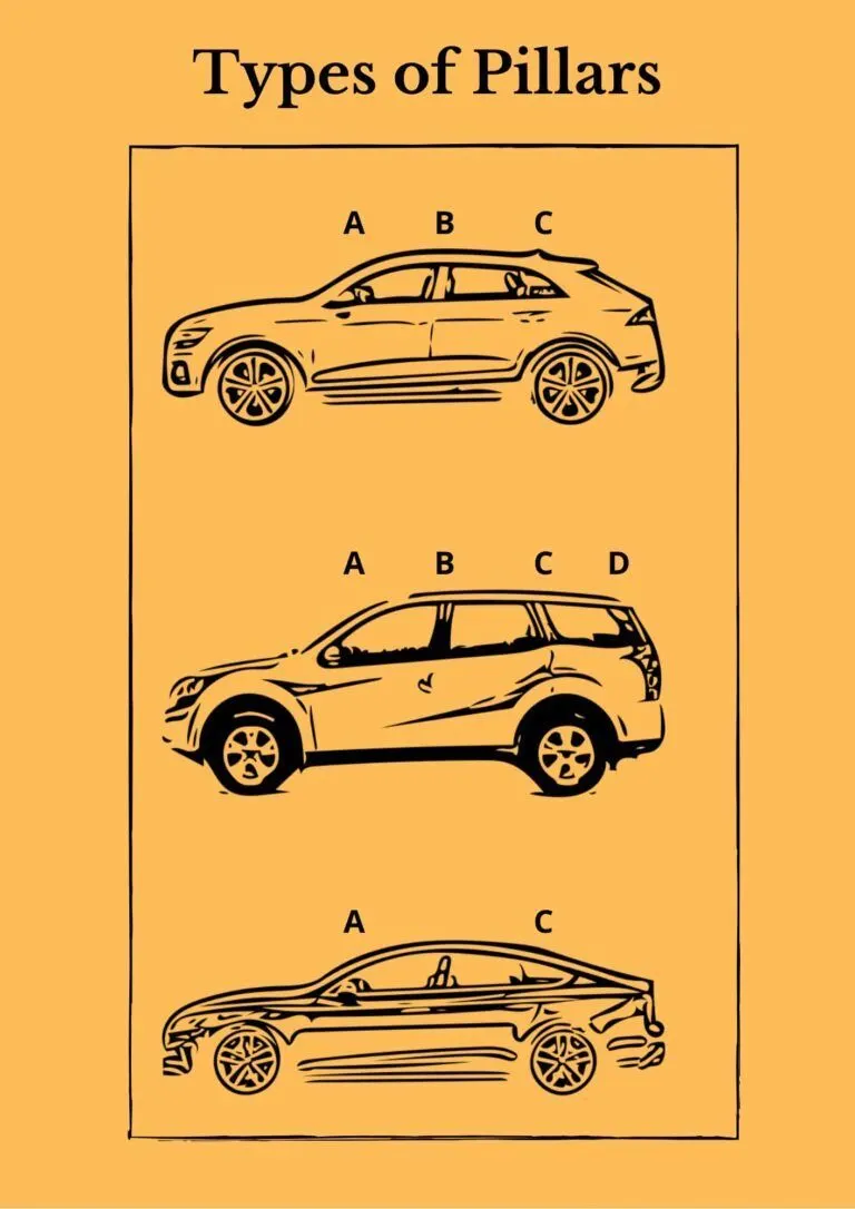
- The number of pillars will vary according to the type of car.Most sedans and hatchbacks will have three (A, B & C) pillars whereas larger cars like SUVs will have all the four (A, B, C & D) pillars.
- Hardtop structures (often referred to as pillarless hardtops) will have only two (A & C) pillars.
- PILLARS are lettered front to back. A-Pillars straddle the windshield, B-Pillars are in the middle of the passenger compartment (just behind the front doors) and C-Pillars are those at the rear of the passenger compartment.
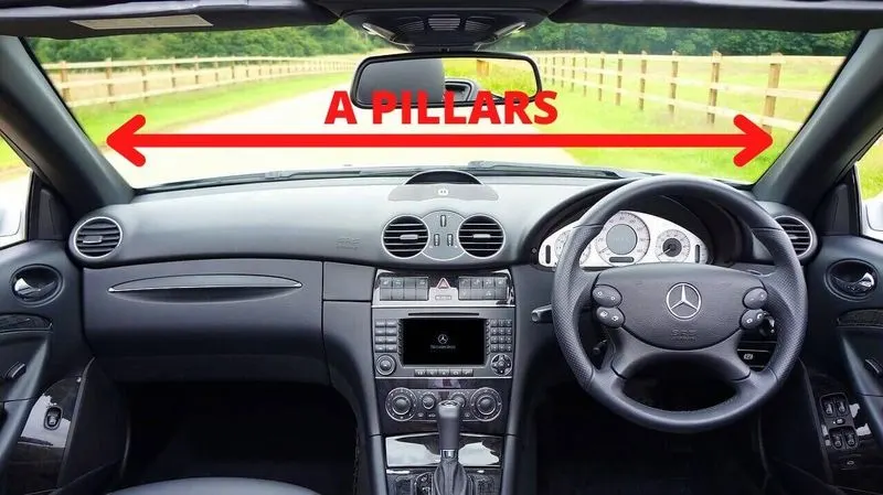
- A pillars are located on either side of your car’s front window (or windshield).They also hold the hinges of your front doors.
MASTER SECTION
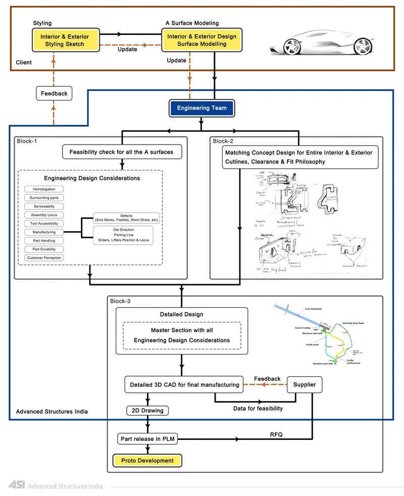
- Master Sections are the guides for design requirements which shapes the component after technical styling of Class A Surfaces.
-
Master Sections are parameterized model of the vehicle body that outlines the guide for NPD Team.
-
Master sections development takes place during feasibility check and concept validation stages of the product life cycle.
- These are typically the guides for design requirements and which decides the component packaging after the development of the concept design, i.e class A surfaces.
- Master section helps us to decide the feasibility of the concept design, the clearances, the packaging and the fixation strategy of a component before converting the concept design into a solid 3D engineering design.
- During the period of vehicle concept design, the evaluation of the master section performance depends mainly on the reference vehicle data and the experience of the structural design engineer.
In this Report B Pillar Cover Creation with detailed procedures of Surface Development and Attachement features are covered
DESIGNING METHODOLOGY:
IMPROVING THE CLASS A SURFACE
The given class A surface is not a proper surface because it is lacking the side flanges so first thing that we have to do is to create the flanges on both the sides of the class A surface.
For creating flanges we will first extract the side edges of A surface and the surfaces touching these edges.
Finally we'll apply the sweep command using the "with reference to the surface" option and join the resulting edges with A surface using trim command.
Make sure that the resulting flanges are properly oriented according to the master section.
Tooling Axis :
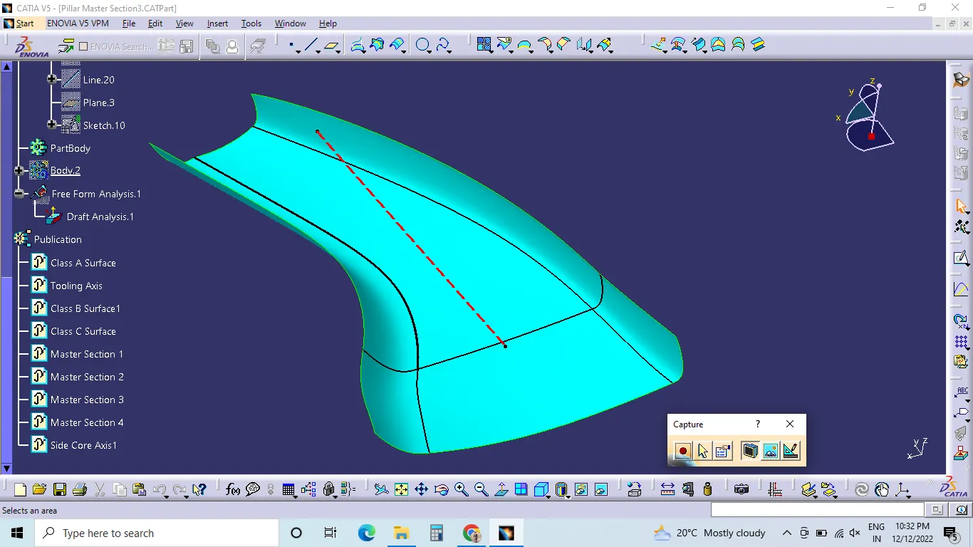
Class-A surface is first analyzed to create the tooling axis or tooling direction that molds pull apart in injection molding. Tooling direction is important for plastic product design as it decides direction for mold seperation.
Tooling Axis Creation :
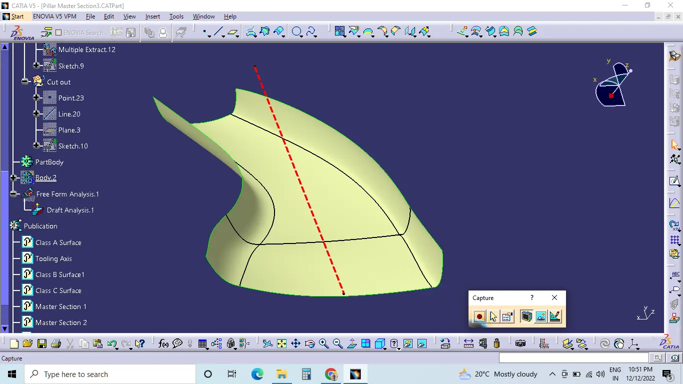
- The next step is to create the tooling axis for the part which will determine the direction in which the core and cavity of the mould will move.
- Designer must ensure that all holes and slots are covered in the main tooling and thus side core must be avoided whenever possible
- After analysing visually for the best possible tooling axis, an reference tooling axis is created on the centre of one of the surfaces of the A pillar trim.
- The main tooling axis is created by using the bisecting method and by taking references from the master section.
Draft Analysis :
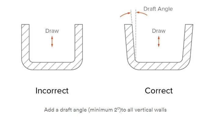
- The Draft angle is the amount of taper for molded or cast parts perpendicular to the parting line. It can be measured in degrees.
- A functional part for injection molding has to have Drafts facing both cavity and core sides to reduce the risk of damage to the parts and ensure ejection. And also important is to overcome the vaccume forces by letting air in between the metal to the plastic for the part to relaese properly. Adding maintaining a decent cosmetic finish.
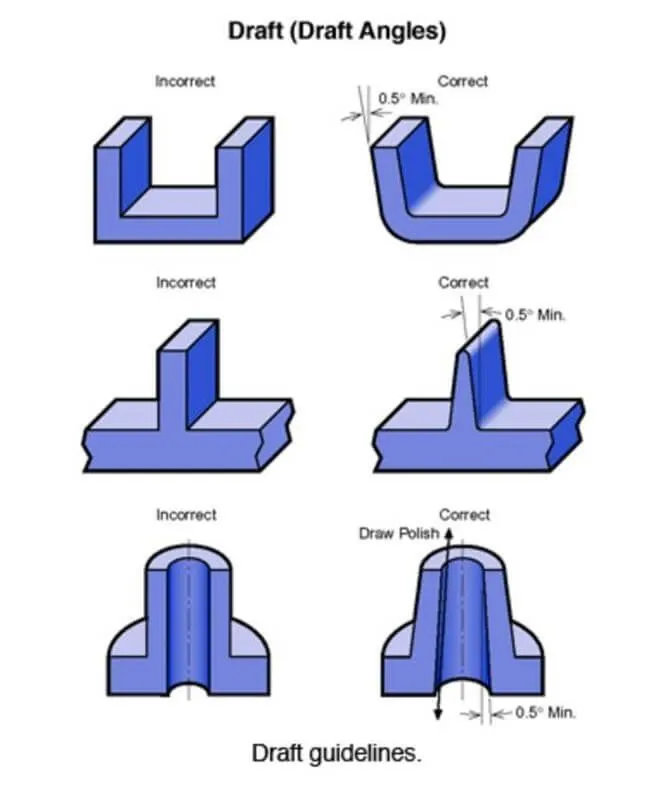
Draft should be a part of design for manufacturing and plastic product Designer should be aware of its need at the outset of the design process. This allows considerations for design requirement to be taken into account.
Nominal values for Draft angle :
- 3 Degrees is the nominal Draft angle.
- 7 Degrees for textured surface.
- At the minimum of 0.5 Degrees can be manufactured by special tools. But it will increase the manufacturing cost.
Draft analysis :
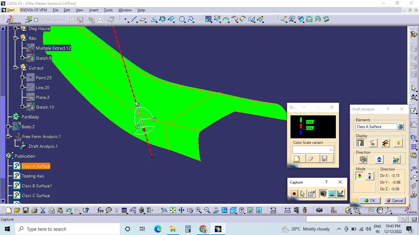
- The part created has to be changed to material mode in display frame.
- Compass is enabled and align it along with the tooling direction.
- Lock command is then classified and Draft angle is applied.
- Color codes are classified and Draft angle is applied.
- Running point analysis is used to display permissible draft angle.
Draft Analysis on Class A Surface:-
CLASS B SURFACE
- After all the validation has been done, the class B surface is created by offsetting the class B surface to a distance of 2.5 mm
- After offsetting a large opening in the surfaces is found which is closed with the help of sweep and multi section commands
- The class B surface is then extrapolated in parts to trim it along with the class C surface
CLASS C SURFACE
- The class C surface which connects the class A and class B surface is created by sweeping the boundary of the class A and using the class A as a reference.
- The sweep is divided into several parts in order to avoid complexity
- Surfaces which are parallel to the tooling direction are swept with the tooling axis as reference and with a draft angle of 3degrees.
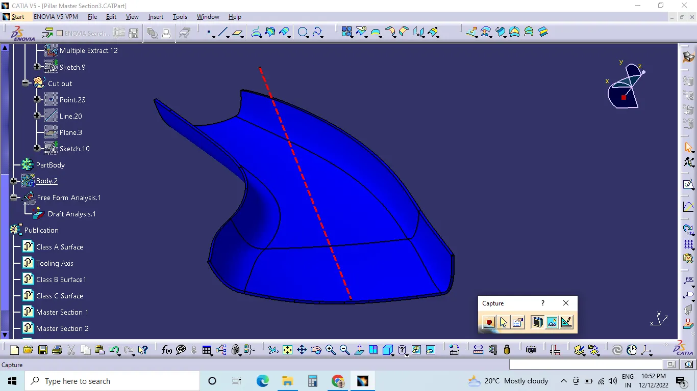
SOLID BODY CREATION OF THE A PILLAR :-
- Using the Trim command join the class A surface with class C surface.
- Trim the resulting Trimmed surface with class C surface.
- The resulting trim we'll get is the closed shell body of A pillar.
- Finally use closed surface command in the part design workbench which would lead the shell body into a part body.
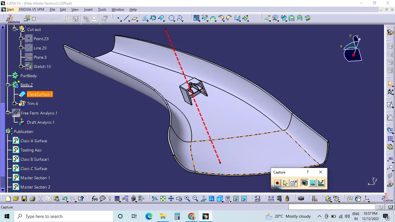
DESIGN OF DOG HOUSE:
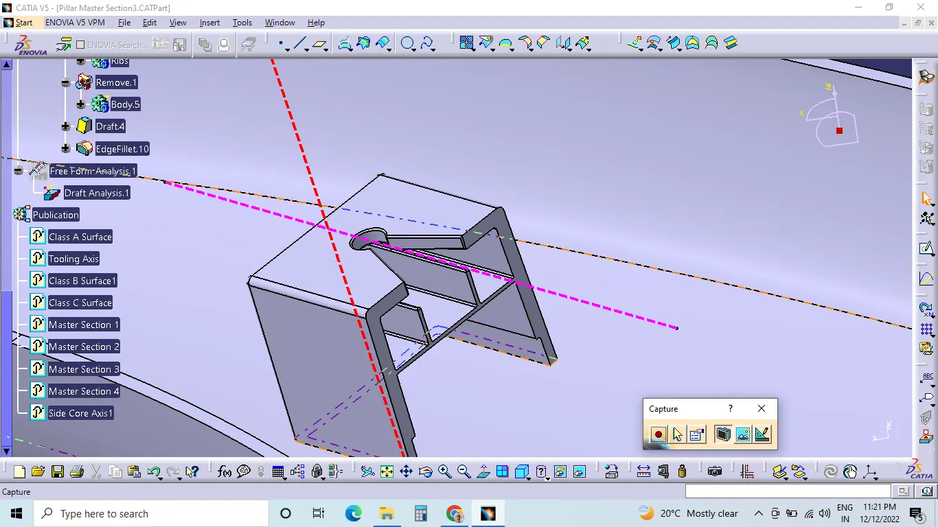
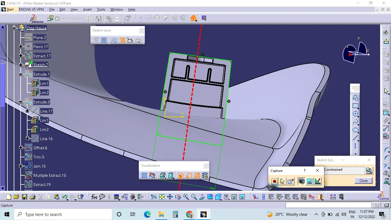
- The two main purposes of a dog house are to avoid sink marks and to house various other engineering features like screw boss, locators etc.
- The dog house should follow certain design rules which are stated below
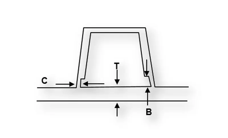
- Doghouse wall thickness at the intersection of the part wall (C) should be 40% or less than the main wall stock (T).
- The height of ( B ) should be between 3.0 – 6.0 mm.
RIBS
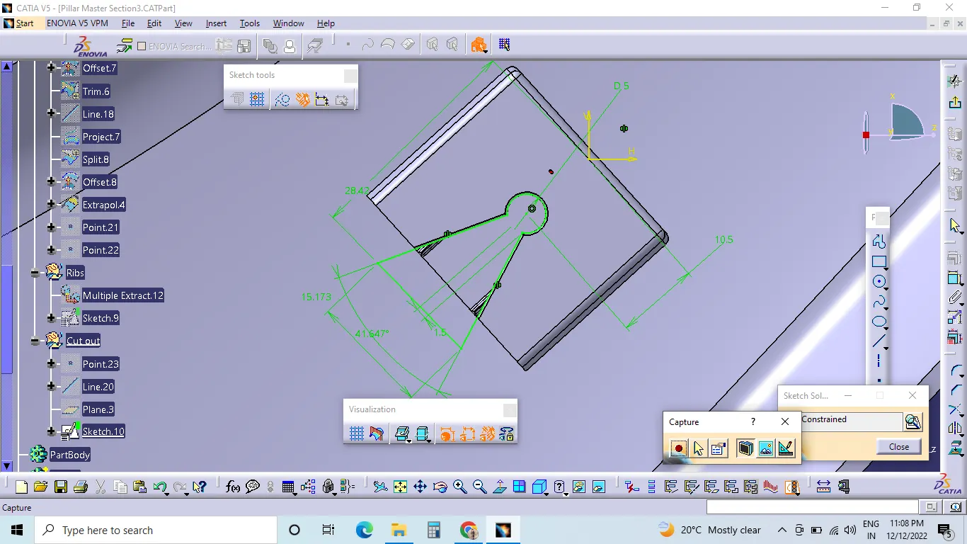
Ribs provide stifness to the parts and can be to impart thougness whthout increasing the part thickenss and are locators and provide allignment to the mating parts
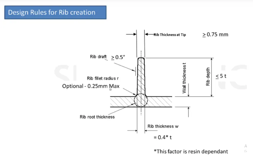
The Design Rules for two way and four way fixtures are
- Rib Wall Thickness should be 0.4 times of Thickness of the part
- The Drafted walls of rib should be within 0.5 degrees
- The top height of rib should be at least 0.70 mm thick to allow the molten plastic to reach the top to avoid Short Shot
- The Thickness of the Rib, Fillet Radius, Draft and rib root thickness are measured and are withing the design specifications
SIDE CORE AXIS:
The side core axis is created to normal to the plane formed along the master section. The dog house inner walls and all the ribs will be cleared using the side core axis.
DRAFT ANALYSIS ON PART:
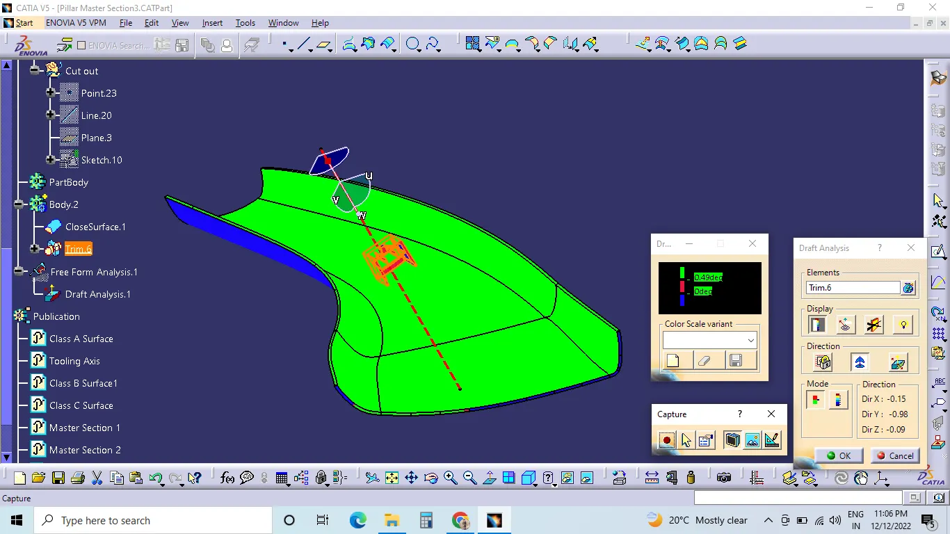
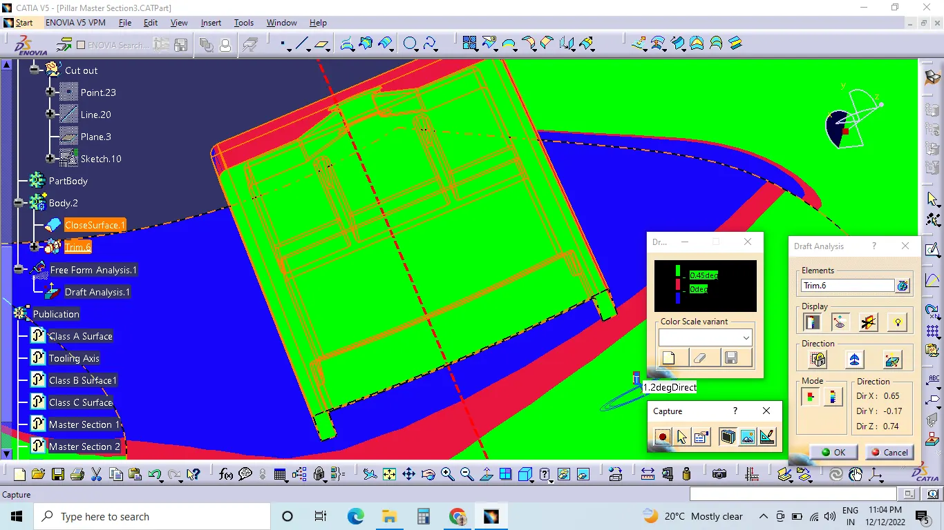
- Draft analysis is done on the final part with the tooling axis as reference
- Green surface indicates the areas where the draft is more than 0.5(>0.45 including clearance) degrees.
- Blue surface indicates the area having negative draft.
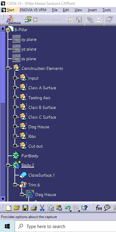
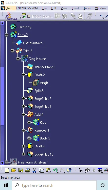
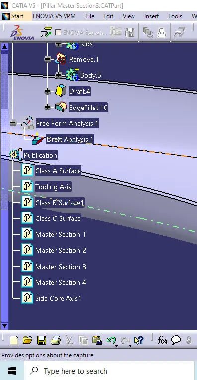
Tree Structure:-
Conclusion:-
Thus a Tooling Axis is created and a open aesthetic Class A Surface is developed into a closed surface with all plastic design rules and a final part body is created.The Design is then validated with Master Section and understood the use of Master Section Development in Product Design through development of B Pillar Cover used in the Car Interiors.