Week 8 - Challenge 1 - Base Bracket Design
BASE BRACKET DESIGN OF A PLASTIC COMPONENT :-
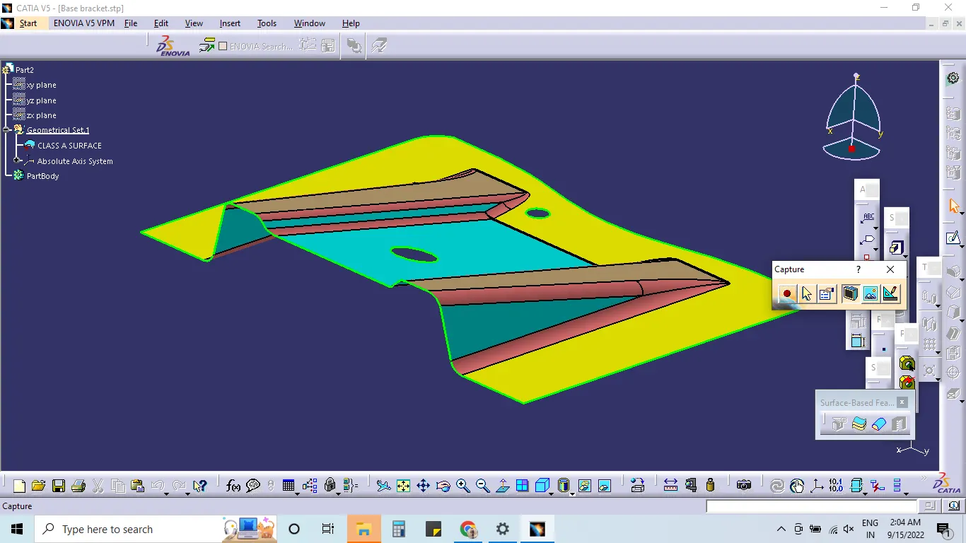
AIM: Create the Base Bracket Plastic component Design through the given CLASS A surface.
This report demonstrates the design of a Plastic Component - Bracket using industry principles such as Draft angles, Draft Analysis, Determining and implementing of Tooling Axis, Class A, Class B and Class C surfaces.
Procedure to be followed while designing base bracket:
- Input Class -A
- Tooling Axis
- Draft Analysis
- Class-B Surface
- Class-C Surface
- Closed Body
Step 1: Design Check on received Class A:
- After receiving the Class-A for the Base Bracket check for the connectivity of the surfaces on it.
- Use Join operation, boundary operation and disassemble.
- The check is over if any discontinuities do not arise.
Step 2: Determine the Tooling Axis:
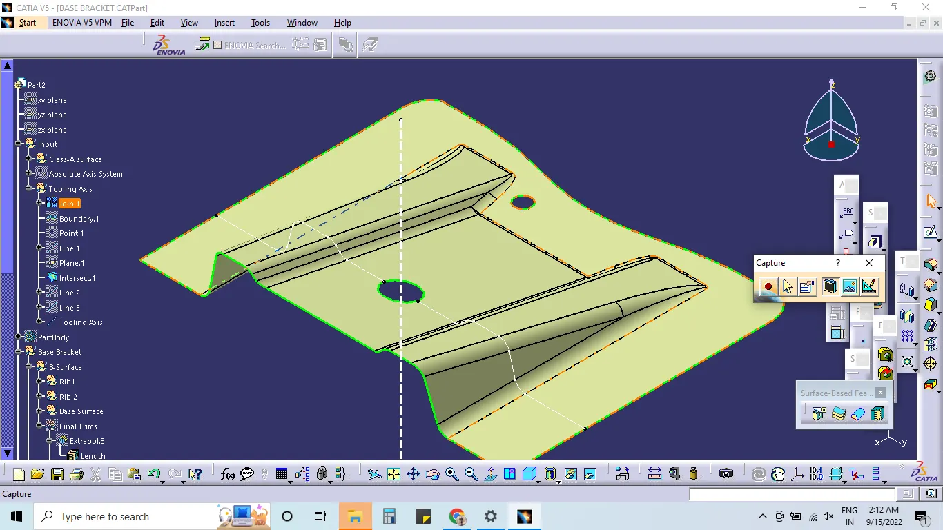
- Create a Dummy Tooling axis along the best possible direction as per the Class A as shown in Figure 6.
- In this case we have chosen Z axis as dummy as it doesn’t interfere with any slots or holes
- Create an Axis System on this line and the center point.
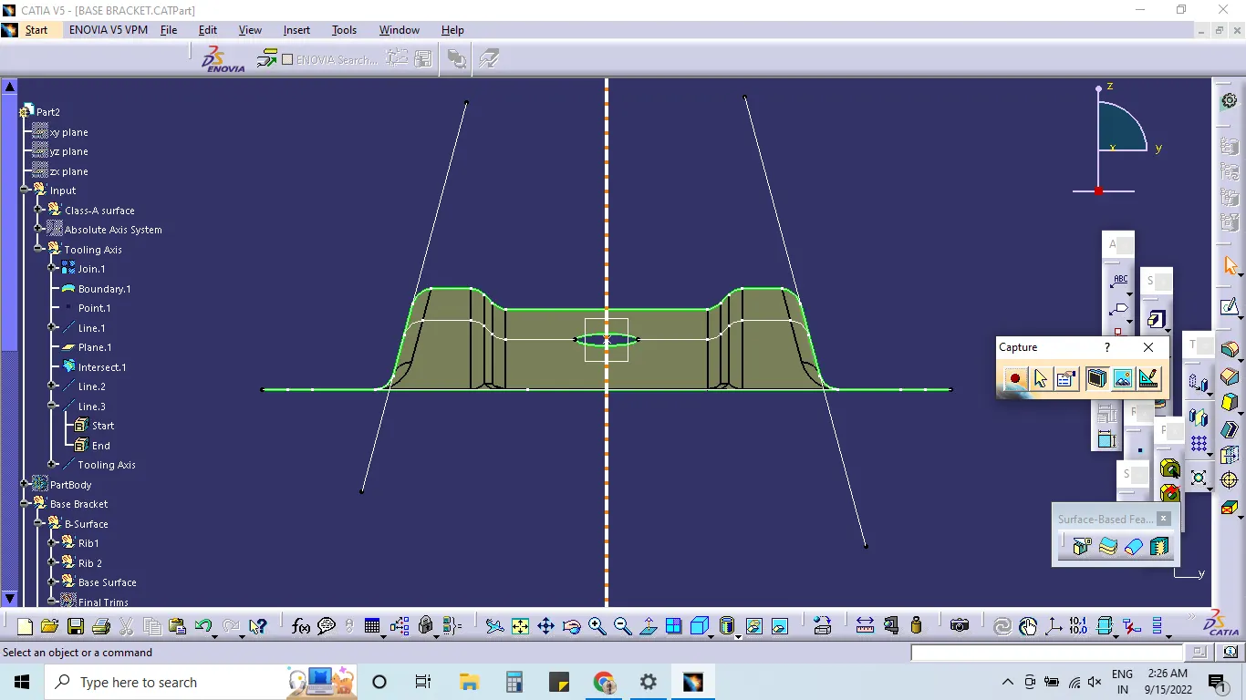
- Create an Intersect between the two planes and the Class A surface i.e., the XZ and YZ plane intersection with the Class A of Bracket.
- In this case the XZ intersection is not required as the faces on this plane have acceptable angles for draft and its analysis is not required.
- Intersection with YZ plane is done as one face tends to be problematic in case of draft.
- Create extended Lines for the faces which may create problems in terms of Draft angles.
- In this case the lines are for the YZ intersect
- Create a Bisecting Line for the extended lines along the center point which is the Tool clearing axis line for Y.
- Since only one axis line exists in this case, we name it as the Main Tooling Axis.
- Publish the Tooling Axis as well as the Class A for easy access using Insert---->Publication.
Step 3: Perform Draft Analysis:
- Change View Mode Customization to Material mode
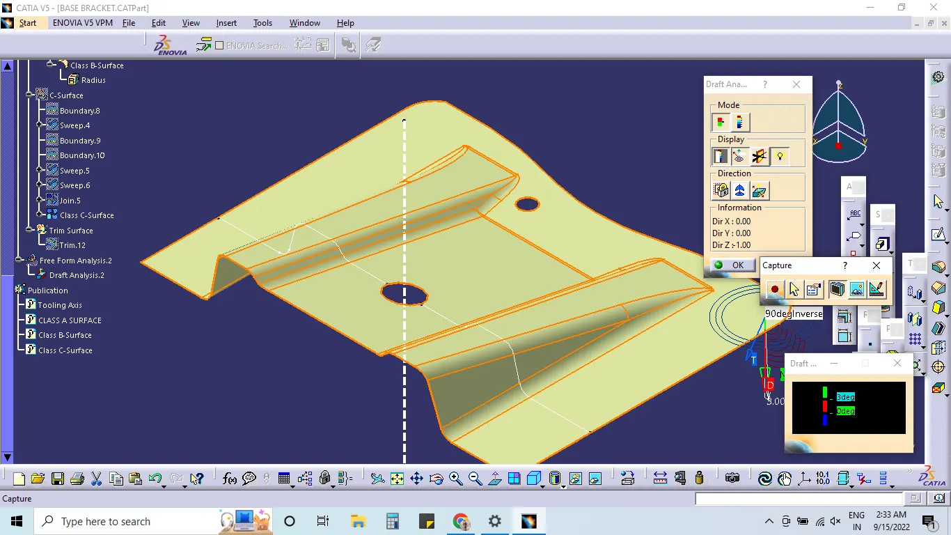
- Go to INSERT ---> ANALYSIS ---> FEATURE DRAFT ANALYSIS and move the compass to the Tooling Axis.
- Change the range to 3º.
- As shown the target area has 15º draft angle which was the concerned face.
- Thus, it passes the criteria of having suitable draft and the Class A can be further designed into plastic component and manufactured.
Step 4:Class B Surface Creation:
- Extract the relevant surfaces from Class-A surface which excludes the Fillets and holes. One example of extract is shown in the Figure.
- Use Untrim Command to untrim the surfaces and create a natural extend.
- Extrapolate the untrimmed surfaces so that each of them intersects clearly and pass way forward than the Class A which will help in its trimming in further operations.
- Trim the extra surfaces to obtain similar extended surfaces as in Class A.
- Offset the obtained Trim to the value of required Thickness of the Part. In this case of Bracket, the thickness value is 2.5 mm.
- Do The Similar operations namely : Extract, Untrim, Extrapolate, Trim, Offset for the other faces from the Class A excluding the Fillets.
- Trim the extra surfaces such that it crates similar surface as Class A.
- Create Fillets while maintaining the part thickness between the Class A and Class b surfaces.
- The Value of Fillet is given by the equation (B surface fillet = A surface fillet + - Thickness of the Part).
- The sign + or – must be decided so as to maintain the part thickness which in this case is 2.5mm.
- Create Fillets while maintaining the part thickness between the Class A and Class b surfaces.
- The Value of Fillet is given by the equation (B surface fillet = A surface fillet + - Thickness of the Part).
- The sign + or – must be decided so as to maintain the part thickness which in this case is 2.5mm.
- The fillet values can also be obtained by maintaining the thickness in the intersection sketch of the two surfaces.
Step 5: Class C Surface Creation:
- Use Boundary option to extract the outer boundary of the Class A surface.
- Use Sweep Operation to extrude the boundary using the Draft direction option and selecting the Tooling Axis as the direction.
- Use draft angle as 3º and Sweep it well beyond the B surface.
- Use similar options of Boundary extract and Sweep for the holes on Class A.
- Join all the Swept surfaces along with the Class A Surface.
- Trim the obtained Joined surfaces with the Class B surface to obtain the final enclosed Surface for the Bracket.
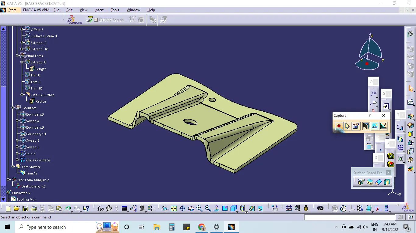
- Switch to Part Design Workbench and use Closed Surface option to create a Solid Part from the final obtained surfaces.
- The part created is the required Base Bracket designed from a Class A.
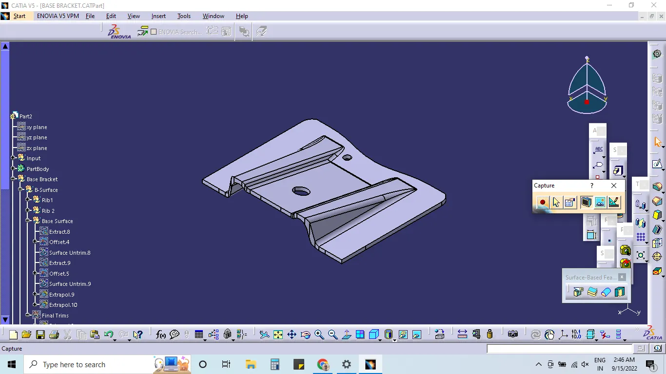
Conclusion:
The Design of Plastic Component - Base Bracket from Class A is completed using concepts of Draft angle, Draft Analysis, Tooling Axis, Class B and Class C creation and converting Closed surface to a solid part.
Class- A Surface:
In automotive design, a class A surface is any of a set of freeform surfaces of high efficiency and quality. It is the visible aesthetic surface of any automotive component. Class A surface refers to those surfaces which are visible and abide to the physical meaning, in a product. This classification is primarily used in the automotive and increasingly in consumer goods industry. It is a requirement where aesthetics has a significant contribution. For this reason, the exterior of automobiles is deemed Class-A.
Class- B Surface:
Class B surfaces are Engineering Surfaces which are invisible to the eyes or often on the back side of the Class A surfaces. It is mainly the thickness of the component or Class A. These surfaces need to be designed as per the Class A surface i.e., the continuity, thickness of the component, functionality etc should be maintained. These surfaces include the main engineering features such as Screw bosses, Ribs, Snaps, Stiffeners and fixations. B surfaces also do not contain any aesthetic styling content and textures since it is not visible to eyes.
Class- C Surface:
Class C surfaces are connectors between Class A and B surfaces. This surface connects both A and B surfaces along the Tooling Axis. It contains the draft as per the design. Its is basically the thickened surface between both A and B surface.
Below Figure 4 shows class A,B and C surfaces: Blue surface is Class A, Green surface is Class B and Red surfaces are Class C surfaces.