Week 8 - Challenge 3 - Coin Holder Design
Aim : To Create a COIN HOLDER plastic component by closed method with reference to a class - Surface.
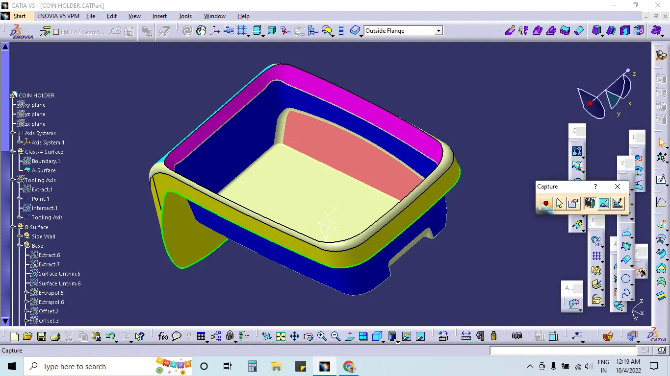
This is the gien Class A Surface
- Class A surface to be checked for the continuity of the surface and ensure it is completly joined and there will be no gap between the surfaces.
- If it is not joined , join together to make it with minimum tolerance of 0.001 to 0.003 and check for connectivity of the surface.
- Connectiity of the surface can be done bytwo ways, by join method and by Boundary method.
- split the surface into multiple profiles then identify the surface, where it is not possible to create tooling axis and check on in which direction it is best fit for tooling axis and then define the tooling axis and draft direction.
--> Creating Tooling Axis:-
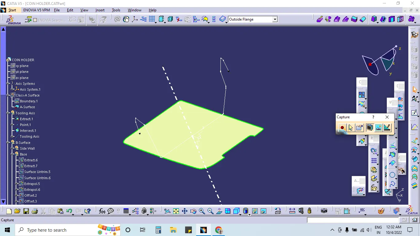
- Extract the base surface from class A surface
- Create a point on the extracted surface using the point command.
- Create a line normal to the surface and this line is our tooling axis.
- Publishing:- Now publish the gien Class A Surface and the tooling Axis.
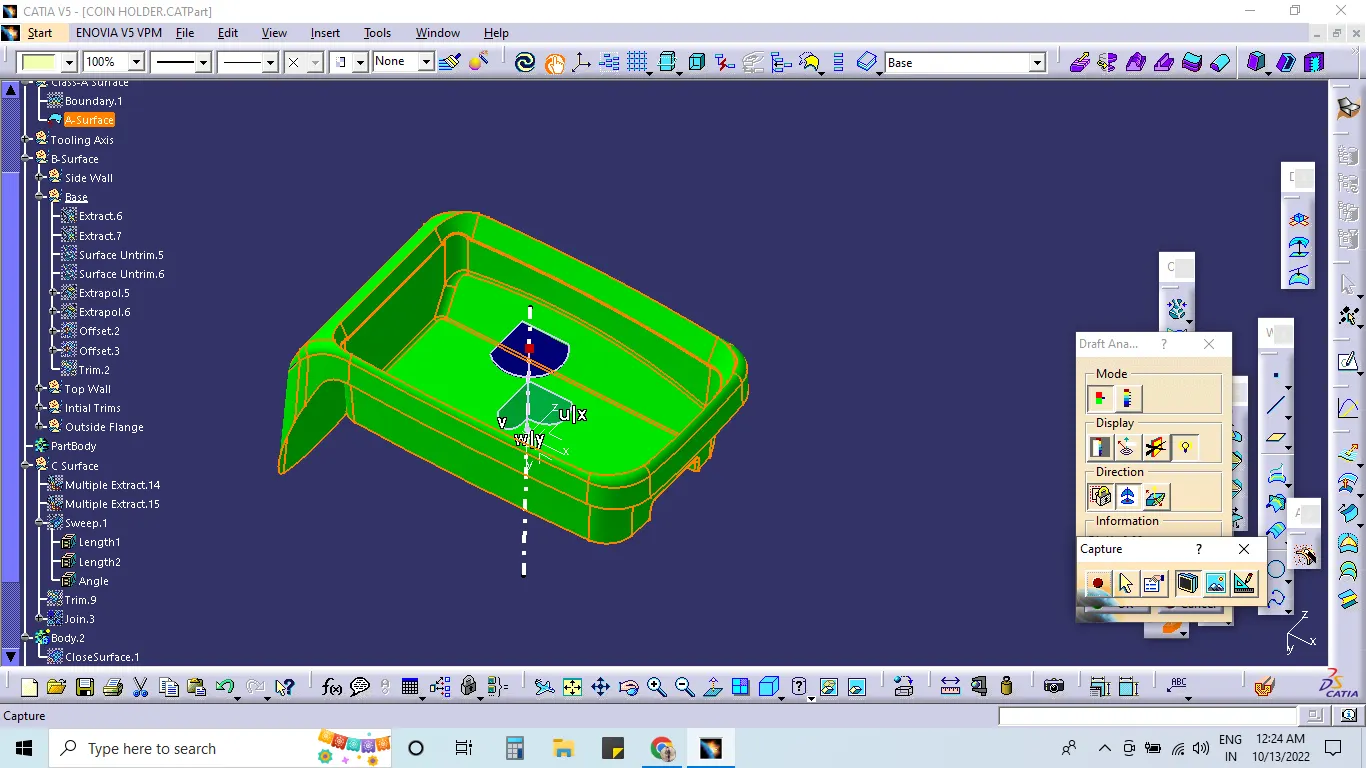
--->Draft Analysis:
--> Class B Surface:-
- Class B Surface is created using the Class A surface.
- Firstly, extract the sides of the base from the Class A Surface.
- Untrim the Surfaces.
- Extra-polate the above surfaces.
- Trim the surfaces together to get a single surface resembling the base in the Class A surface.
- The thickness of the component is 2.5mm so the above surface needs to be offset to a distance of 2.5 mm.
- Repeat the same Procedure to make the Side Walls.
--> Upper Walls :-
- Extract the upper wall surface from class A surface using the Multi Extract feature including the fillets.
- Extrapolate the above surface using point and curvature continuity and create an offset of 2.5mm outward]
- Then trim With the preious surface.
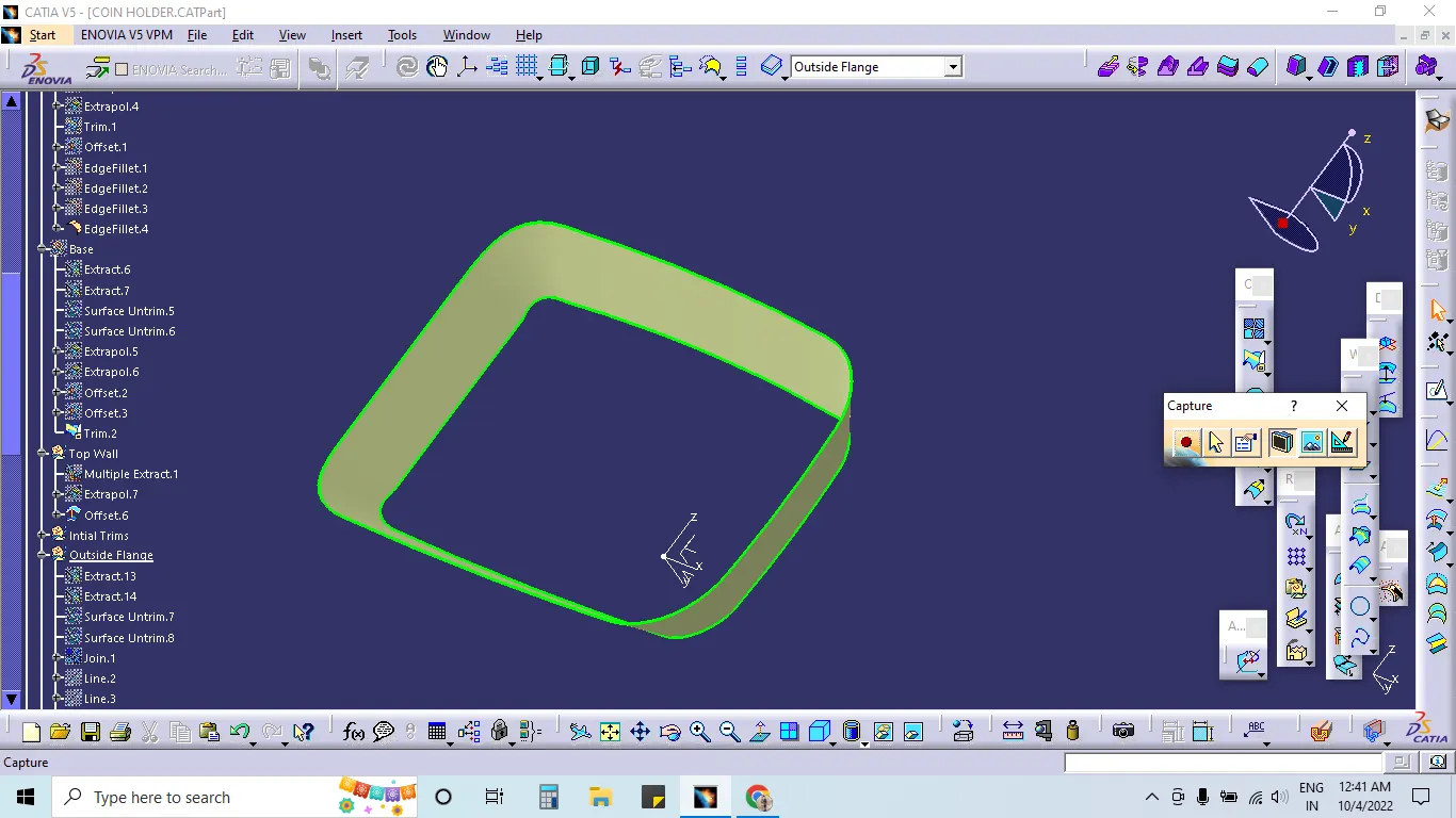
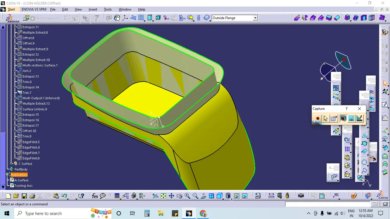
--> Outer Flange:-
- The outer flange surface needs to be created in two steps.
- Firstly, extract the enclosing surface from the Class A Surface.
- Extrapolate the above-extracted surface using the curvature sand point continuity.
- Now, extract the remaining surfaces of the outer flange from the Class A Surface.
- Untrim the above-extracted surfaces and join them using the 'Join' feature and then extrapolate the resulting surface.
- Create offsets of the above surfaces. The offset needs to be created inwards because the outer flange surface in Class B Surface will be below the outer flange surface in Class A Surface:
- Finally, trim the surfaces together and provide a different colour to the resulting surface.
--> Fillets:-
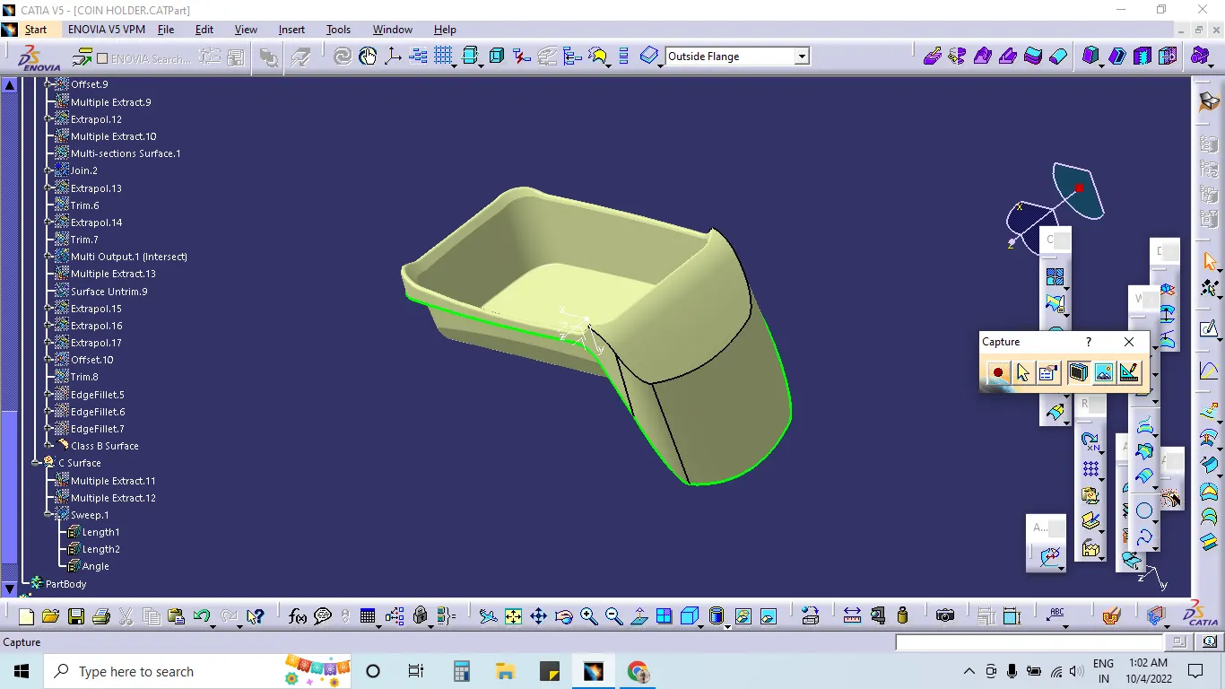
- Now, the fillets are applied to all the edges using the measurement from the Class A Surface and the thickness of 2.5 mm.
- Firstly, provide the fillet at the top edge.
- Provide the fillet at the base edges.
- Similarly, provide the fillets to the sidewall edges. The final surface after filleting is the Class B Surface.
--> Class C Surface :-
- EXtract the enclosing walls of the outer flange using the Multiple extract feature.
- Extract the boundary of the Class A Surface.
- Use the Sweep feature, with Subtype as 'With reference Surface'. Choose the guide curve 1 as the above-extracted boundary and the reference surface as the above-extracted surface from the Class A Surface. choose the angle as 90 degrees.
- Now, the Class C Surface for the section needs to be created.
- Extracted the boundary of the section and the nearby surfaces.
Final Trims :
- Firstly trim Class B and Class C Surface of the section
- Now trim the above surface and the class C surface
- Finally trim the above surface and class A Surface to get the final enclosed surface.
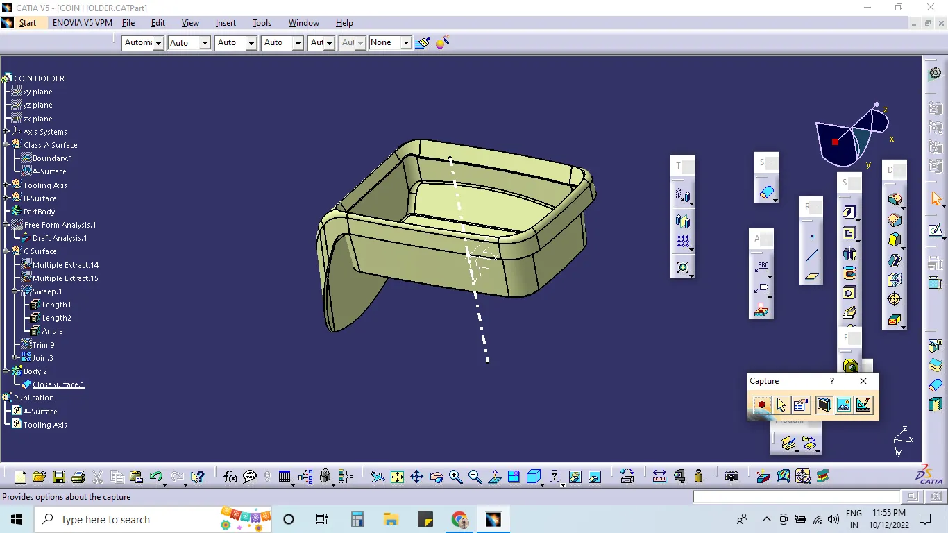
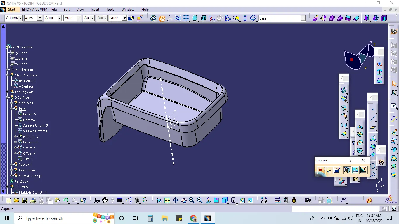
Now convert the given model into solid body using Closed Surfacefrom the Part Workbench.
--> Draft Analysis:-
- For Draft Analysis we need the solid body and the tooling axis.
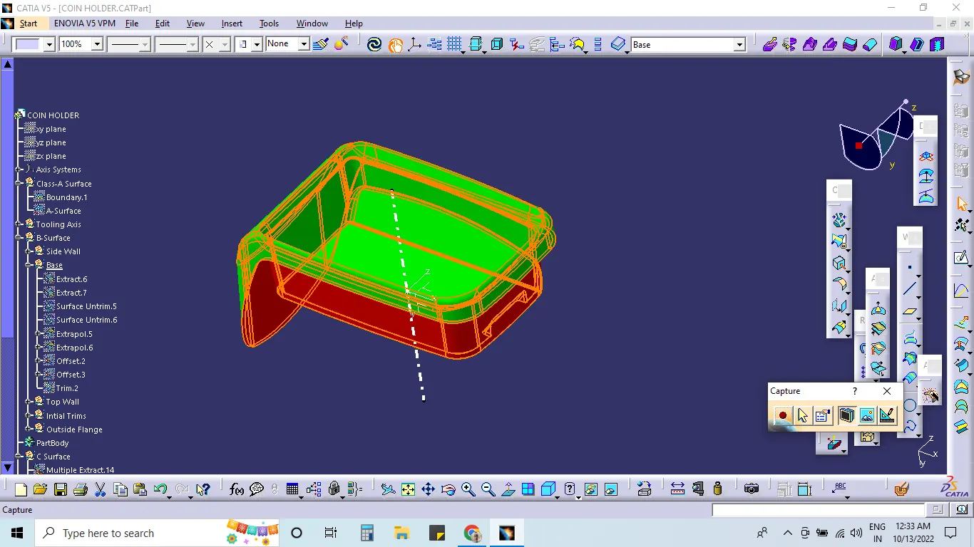
--> Conclusion:-
- Class B and Class C Surfaces are successfuly created from the given Class A Surface.
- Class A, Class B and Class C surfaces are trimmed together to create the final closed surface.
- The Solid Body is successfully created and performed the draft analysis.