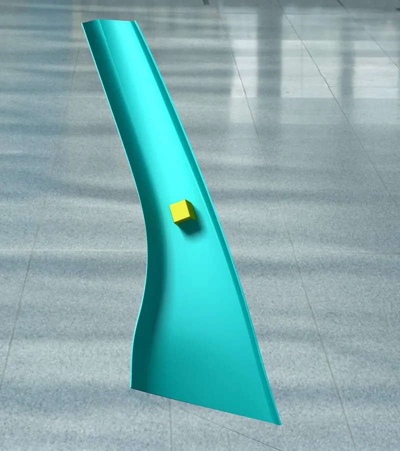
Week 9 - Project - A pillar Design with Master Section
DESIGNING A PILLAR USING MASTER SECTION
OBJECTIVES
- To improvise the Class A surface by resolving bad patches and adding flanges to it.
- To create A pillar solid model with the help of improvised class A surface.
- To create B side features for the A Pillar using the master section given to us as an input.
- To create main and side core tooling axis for A pillar and its B side features.
- To do the draft analysis of the overall model of the A pillar i.e including B side features.
INTRODUCTION
MASTER SECTION: Master sections development takes place during feasibility check and concept validation stages of the product life cycle. These are typically the guides for design requirements and which decides the component packaging after the development of the concept design, i.e class A surfaces.
Master section helps us to decide the feasibility of the concept design, the clearances, the packaging and the fixation strategy of a component before converting the concept design into a solid 3D engineering design.
During the period of vehicle concept design the evaluation of the master section performance depends mainly on the reference vehicle data and experience of structure design engineer.
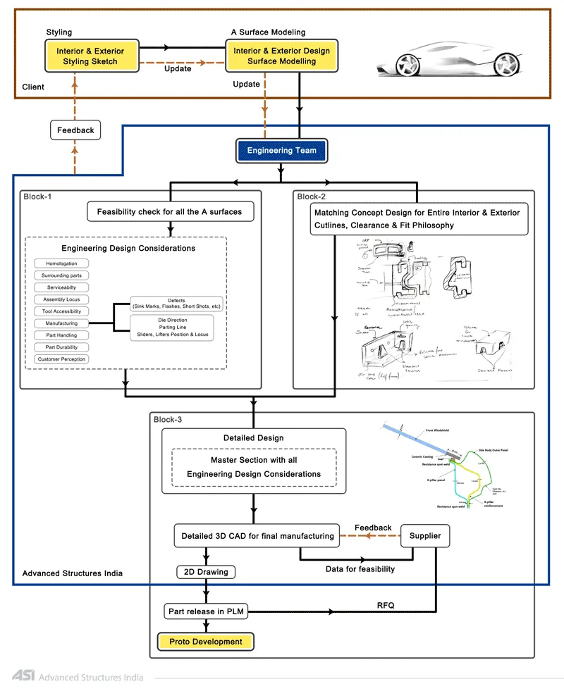
Procedure
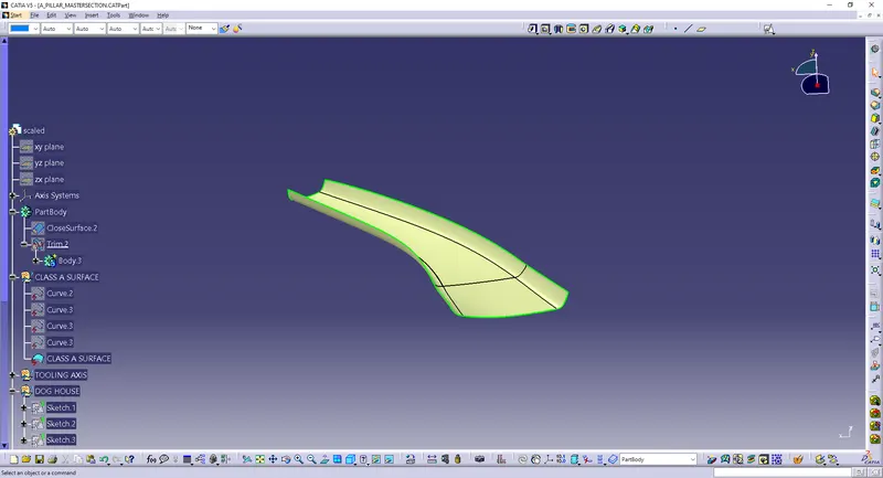
Below is the class A surface which was incorporated in the Catia V5 work bench to work upon.
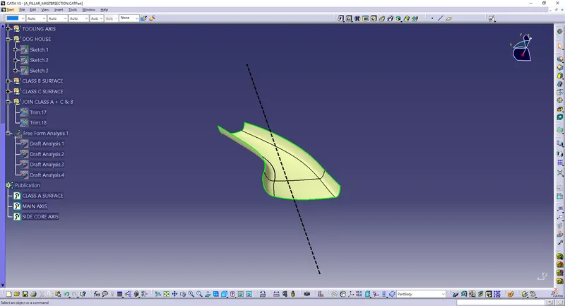
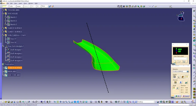
Tooling axis & Draft Analysis: The direction in which the mold or core and cavity opens is the tooling axis.
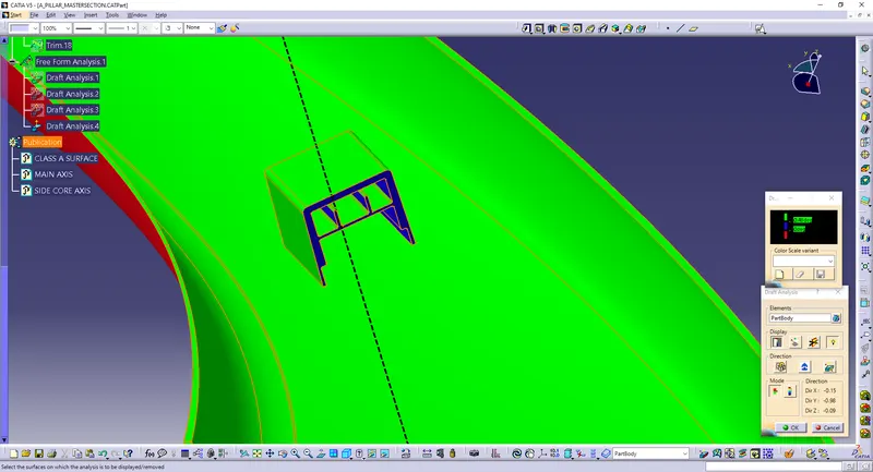
To create the tooling axis, I extracted a surface from class A and created a point in the middle of the surface by using the point command and created a line at that point through the x-axis. Now, I performed a draft analysis check from that line whether the created tooling axis is in the correct position or not. If, in the draft analysis check the surface highlighted with green colour on both sides of the surface the tooling axis is in the correct position and direction.

CLASS B SURFACE:
To create the class B surface, offset the class A surface inside as per our thickness requirement ( I offset the class A to 2.5mm inside). Once the offset is created, we can observe some patches on the offset surface by taking the boundary for the offset surface, those patches are formed due to the fillets on the class A surface. We need to cover those patches with the help of the multi-section surfaces command by extracting the patch boundaries. Once all the patches on the offset are covered properly join all the patches with the offset surface, to get the replicated surface of the class A surface.
PATCH-1
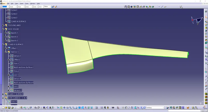
Repaired Patch-1
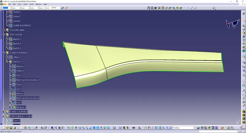
After Filling Patches Class B Surface
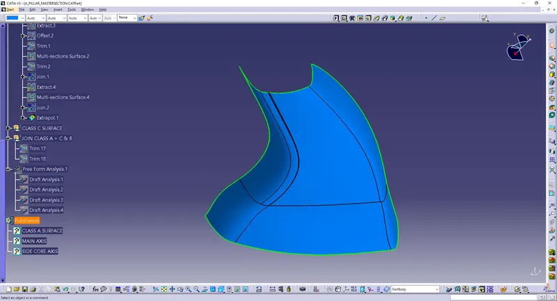
CLASS C SURFACE:
To create the class C surface concerning the boundary of the class A surface, I used the sweep command. Initially, I extracted the boundary of the class A surface with tangent continuity, and I sweep the extracted boundary concerning the surface at 90deg (for reference Surface) for 5mm to intersect properly with the class B surface. Once we sweep all the surface boundaries of class A, extrapolate the sweeped surfaces until both surfaces got intersected properly, and trim them to remove extended extrapolated surfaces to get a proper sweep boundary throughout the entire surface, including the centre hole of the Door trim lower.
Class C Surface
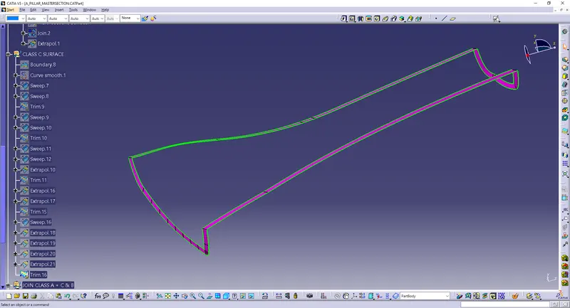
Now, join both class A and sweep boundary to get the complete class C surface.
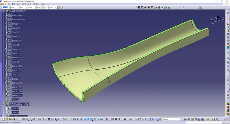
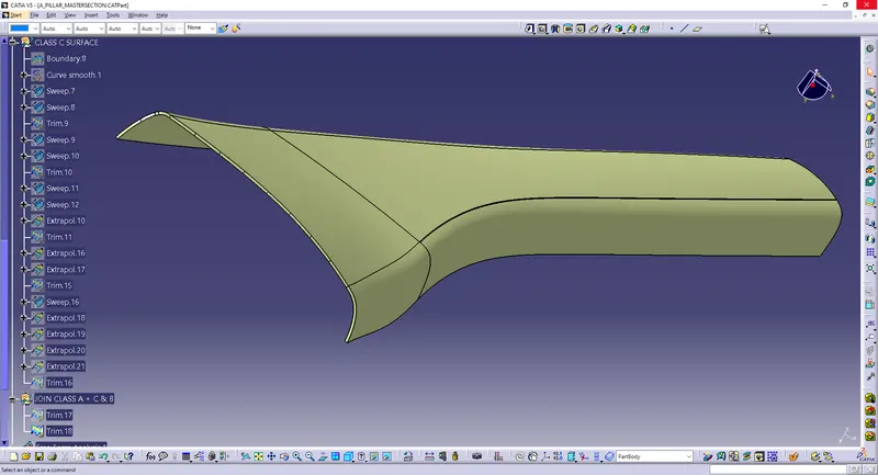
Now, unhide the class B and class C surfaces. Check whether all the sides of class B and Class C surfaces are intersecting properly with each other, to get a closed surface by trimming class B and class C surfaces. If the class B and class C sides are not intersected properly, we need to extrapolate the sides of the class B surface which are not intersecting with the class C surface. Now, check class B and class C surface boundaries whether all the sides are intersecting or not with each other. Once the surfaces are intersecting properly trim them together to get a closed surface.
CLOSED SURFACE
Trim
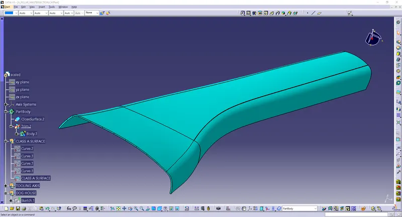
PART BODY:
To create the solid part body from the closed surface, I used the closed surface command in the part workbench.
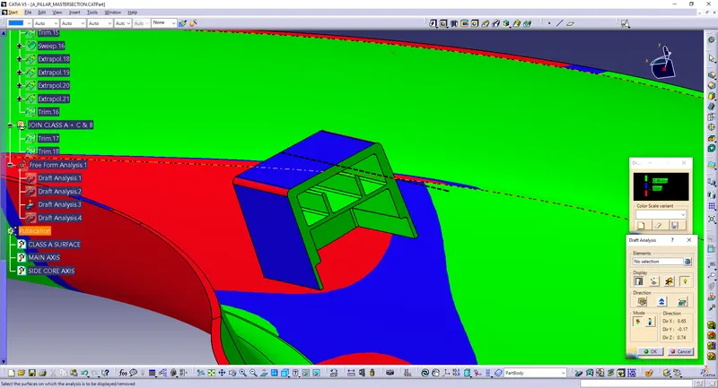
SIDE CORE AXIS
create side core axis using master section.
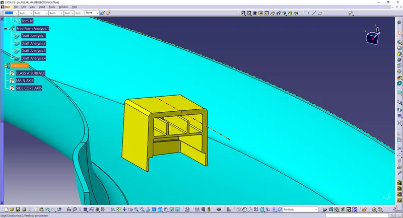
DOG HOUSE
Create the dog house as per master section.
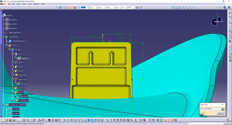
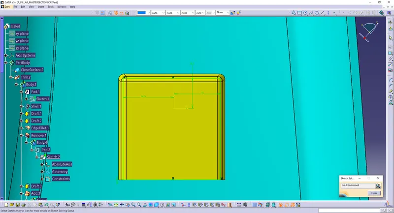
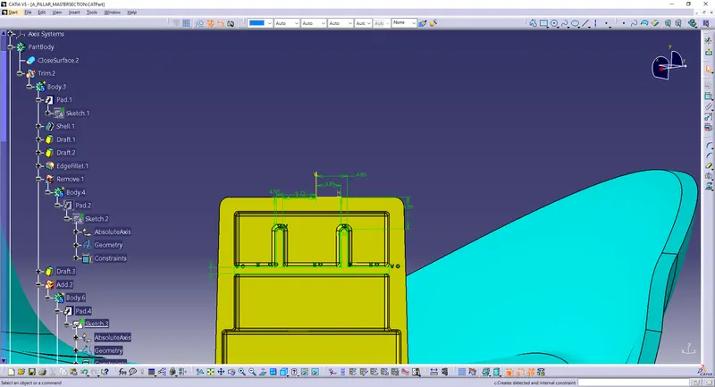
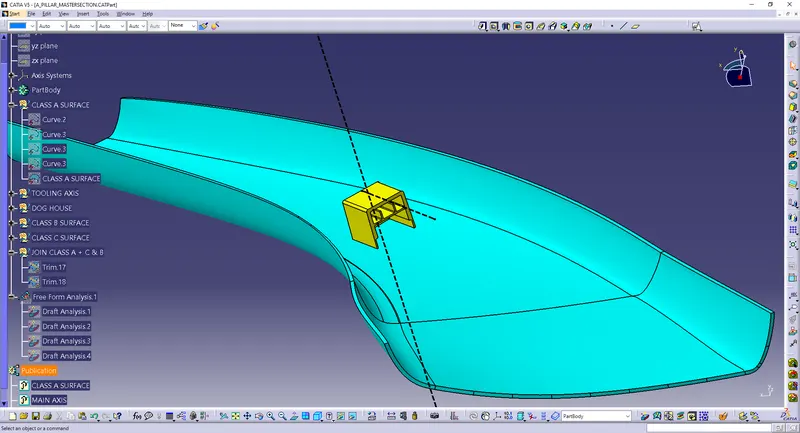
DRAFT ANALYSIS FOR SOLID SURFACE
Main Axis Draft Analysis
Side Core Draft Analysis
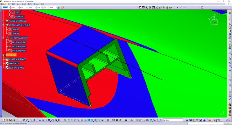
Rendered Image