Week 8 - Challenge 4 - Bumper
BUMPER DESIGN :-
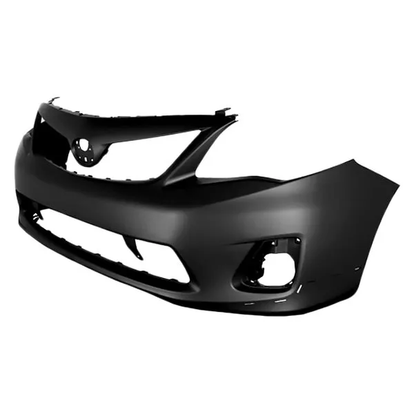
what is bumper?
A device for absorbing shock or preventing damage (as in collision).
which material is used for Bumper? why?
- Polycarbonate (PC) & Acrylonitrile Butadiene Styrenel (ABS) thermoset platice are used to manufacture the bumper. But Mostly they use Acrylonitrile Butadiene Styrenel (ABS) Because it helps to absorb and redistribute energy during an impact to keep Passenger safe & it's helps to improving the material quality with that it reduce the production cost & to increase the focus of aesthetics look compared to Polycarbonate (PC).
Objective: The main objective of this challenge is to create a solid body of 'Bumper' with the help of the closed surface method by using the 'Generative shape design' workbench in CATIA V5. Performing the 'Draft Analysis' on the solid part body of the Bumper.
Overview:
Initially, we need to offset the given Bumper class A surface in the inner direction to the required thickness (here the thickness is 3mm). After that, we need to close the patches on the offset surface of the bumper, the patches are formed due to the fillets on the Class A surface. Once all the patches are closed properly join them together to make a proper class B surface and now sweep the boundary of the class A surface to trim with the class B surface to make a closed body. By using the closed body command in the Prat workbench we can get the solid body from the closed surface of the Bumper. Now, again went back to the surface workbench to perform the 'Draft analysis' for the solid body.
Class A Surface-
Class A Surface is the asthetic sutface that is created through scaning of clay model. This Class a Surface is a input CAD model for part design.
Class B surface-
Class B surface is created in a certain distance according to the thickness of the part. Class B Surface contain all engineering component.
Class C Surface-
Class c Surface joins the Class A & Class B Surfaces.
The steps involved in creation of this project are:
1. Bringing the class A surface of the Bumper in Catia v5 software.
2. Determining the tooling axis for the Bumper.
3. Creation of class B surface.
4. Creation of class C surface.
5. Joining all the class A, class B and class C surfaces of the Bumper.
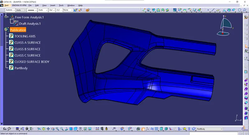
6. Building closed surface after joining all the surfaces.
7. Draft analysis on the Bumper.
METHODOLOGY:
In this model we have focused on the following things:
- Tooling axis
- Draft analysis
- Class-B surface
- Class-C surface
- Making a solid model from surface.
Following tools were used to reach the final step:
- Trim
- Extrapolate
- Offset
- Boundary
- Sweep
- Join
- Close (part design)
Procedure
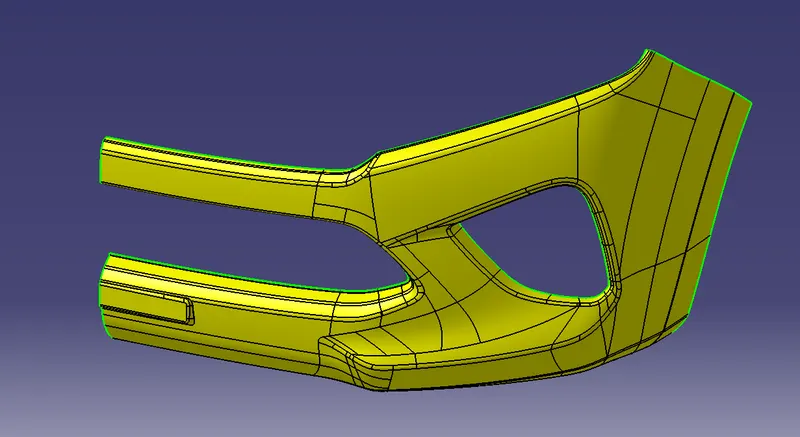
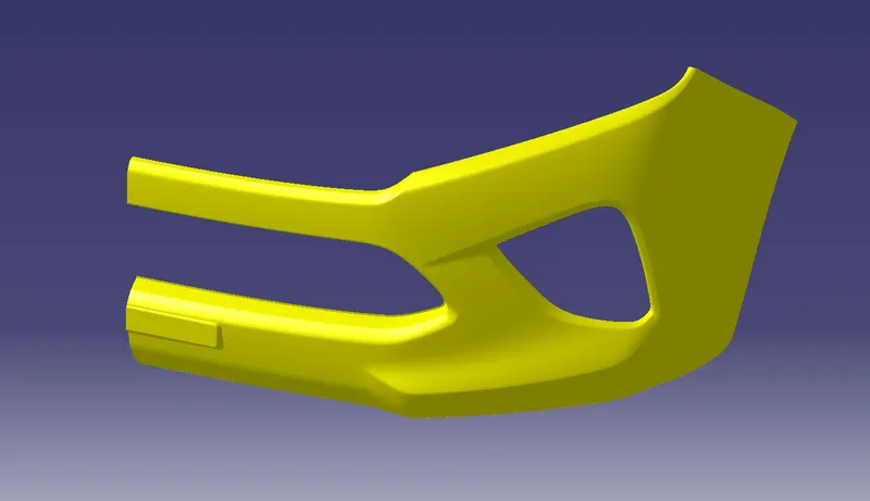
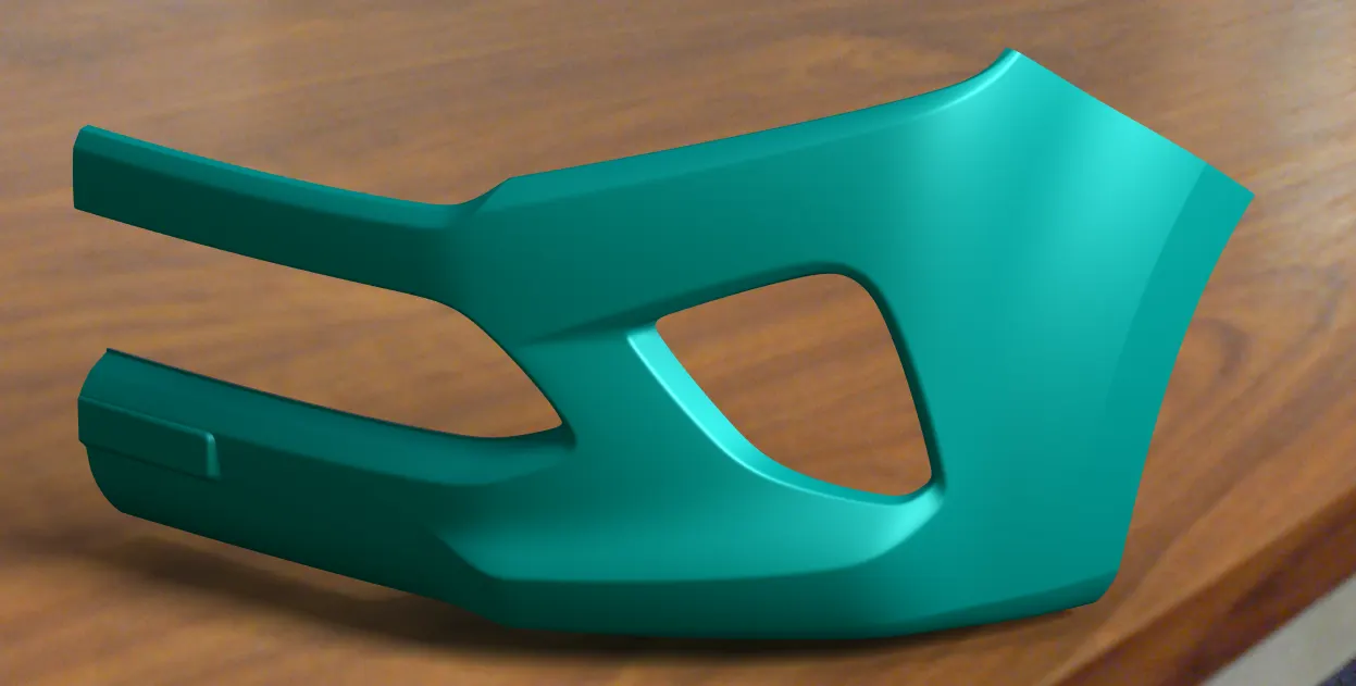
Below is the class A surface which was incorporated in the Catia V5 work bench to work upon.
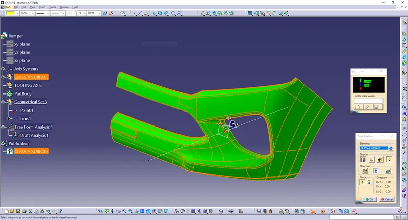
Tooling axis: The direction in which the mold or core and cavity opens is the tooling axis.
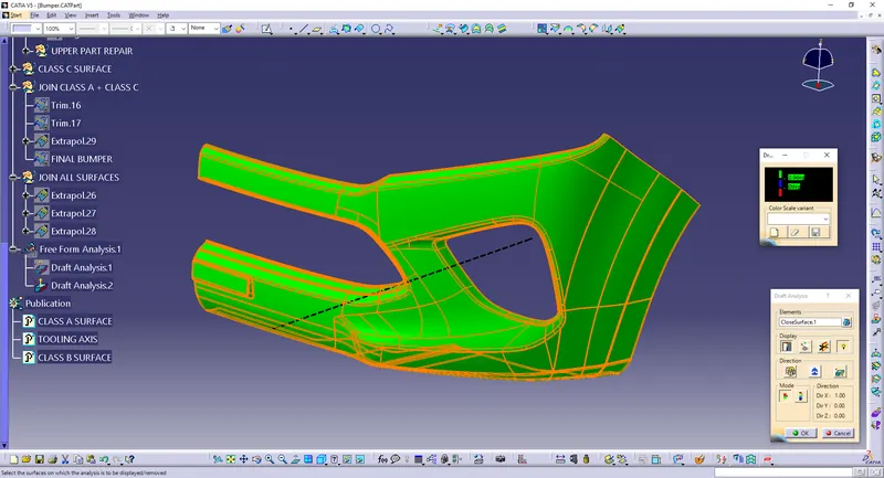
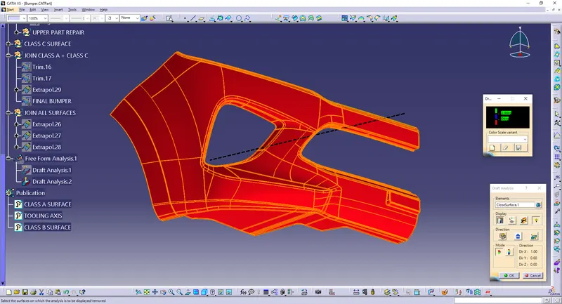
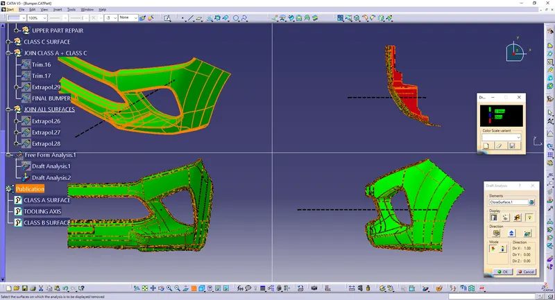
To create the tooling axis, I extracted a surface from class A and created a point in the middle of the surface by using the point command and created a line at that point through the x-axis. Now, I performed a draft analysis check from that line whether the created tooling axis is in the correct position or not. If, in the draft analysis check the surface highlighted with green colour on both sides of the surface the tooling axis is in the correct position and direction.
CLASS B SURFACE:
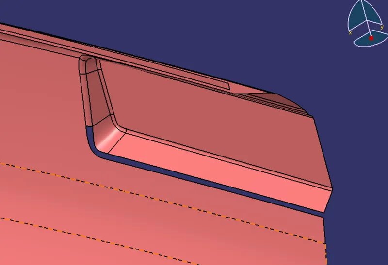
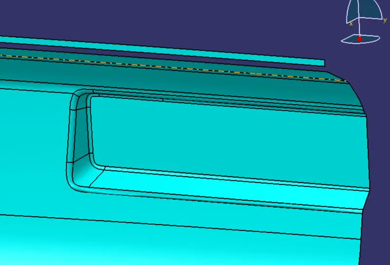
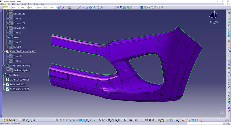
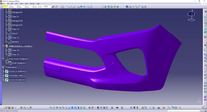
To create the class B surface, offset the class A surface inside as per our thickness requirement (here the thickness is 3mm, so I offset the class A to 3mm inside). Once the offset is created, we can observe some patches on the offset surface by taking the boundary for the offset surface, those patches are formed due to the fillets on the class A surface. We need to cover those patches with the help of the multi-section surfaces command by extracting the patch boundaries. Once all the patches on the offset are covered properly join all the patches with the offset surface, to get the replicated surface of the class A surface.
PATCH-1
Patch-2
Patch-3:
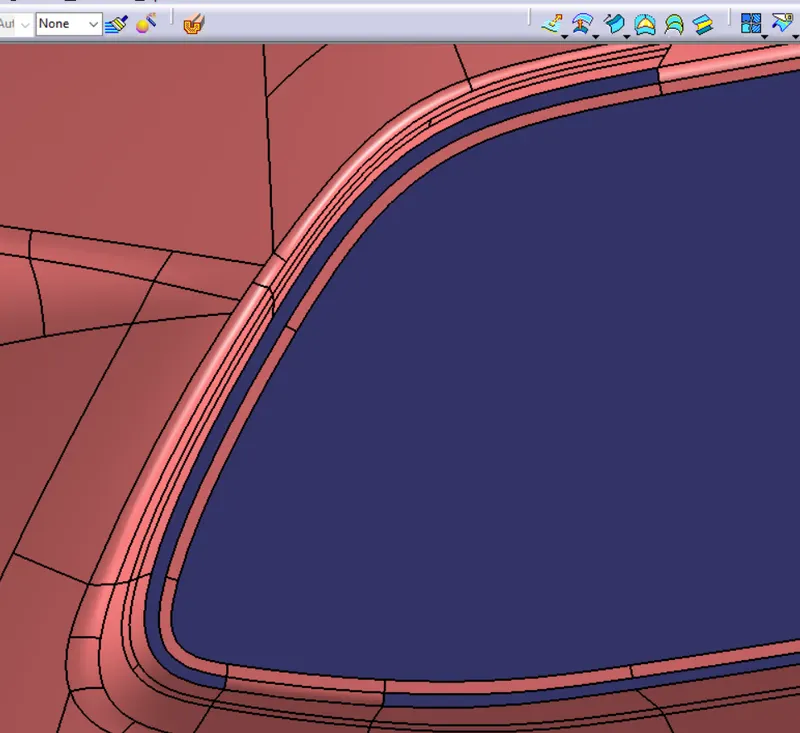
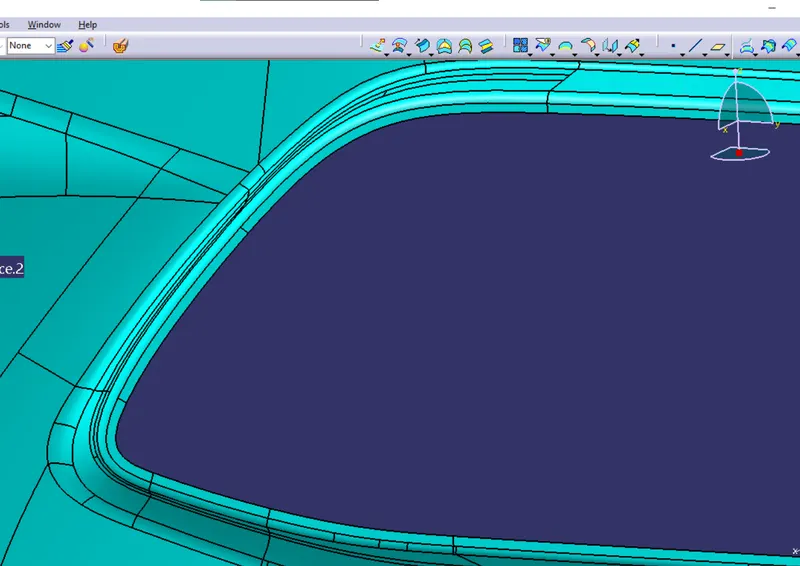
Patch-4:
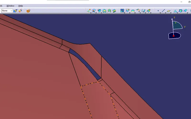
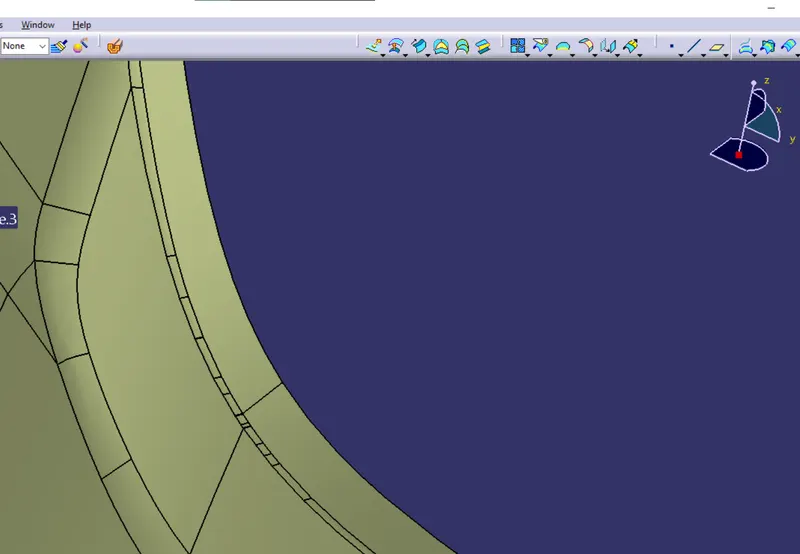
Patch-5:
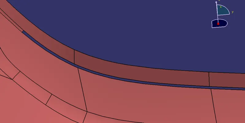
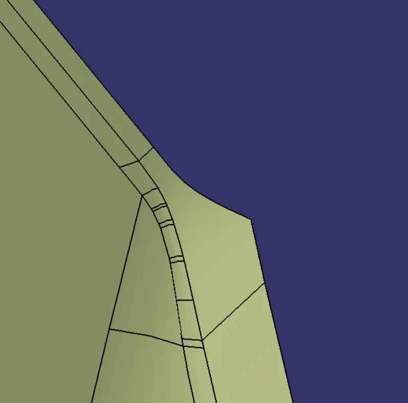
Patch-6:
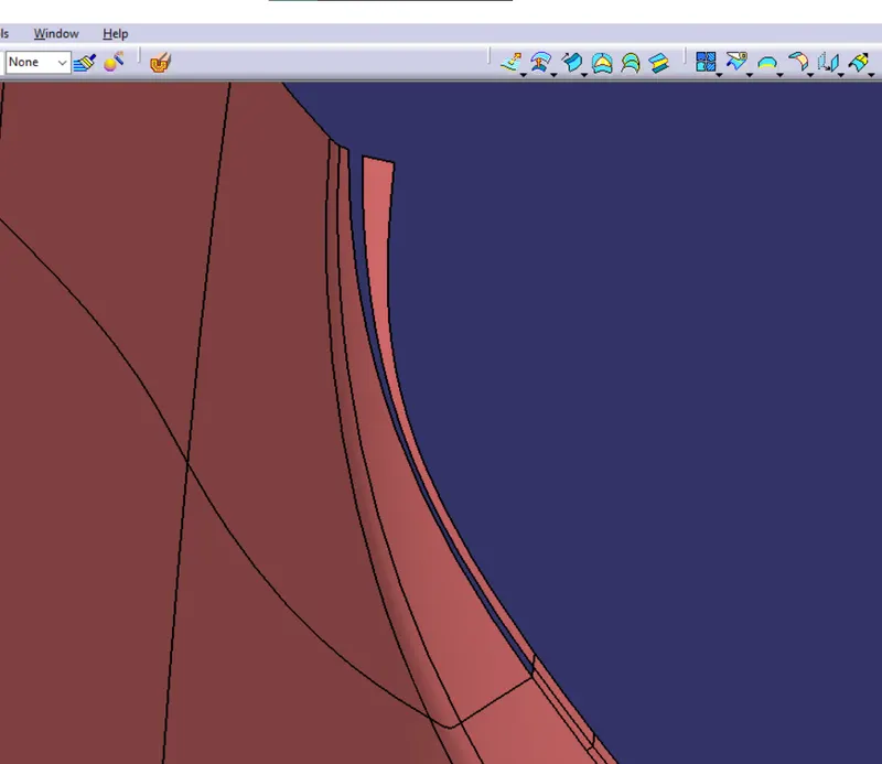
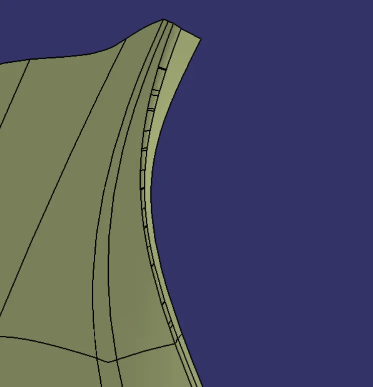
CLASS C SURFACE:
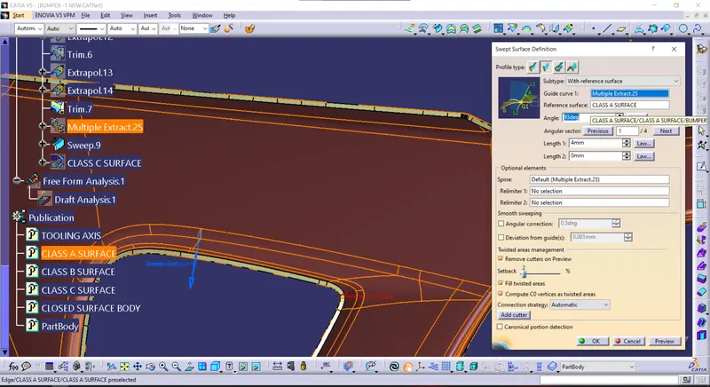
To create the class C surface concerning the boundary of the class A surface, I used the sweep command. Initially, I extracted the boundary of the class A surface with tangent continuity, and I sweep the extracted boundary concerning the surface at 93deg (for draft angle) for 4mm to intersect properly with the class B surface. Once we sweep all the surface boundaries of class A, extrapolate the sweeped surfaces until both surfaces got intersected properly, and trim them to remove extended extrapolated surfaces to get a proper sweep boundary throughout the entire surface, including the centre hole of the bumper.
Now, join both class A and sweep boundary to get the complete class C surface.
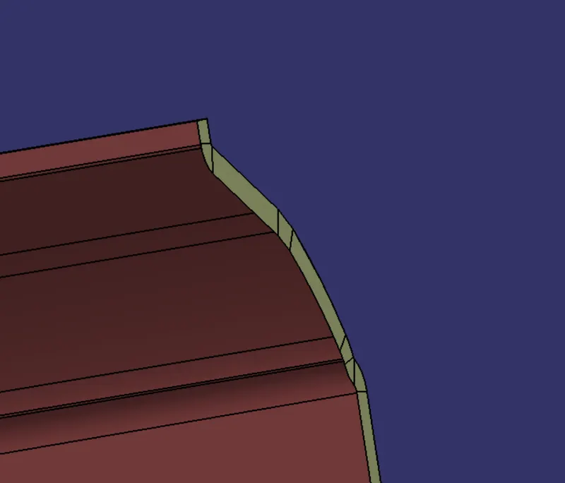
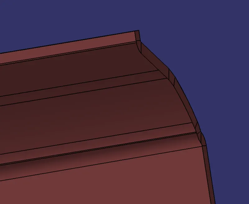
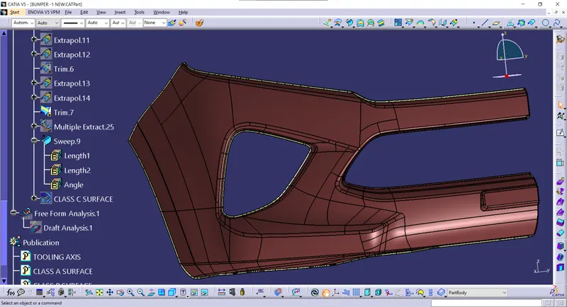
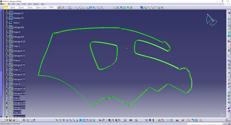
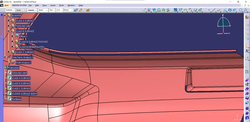
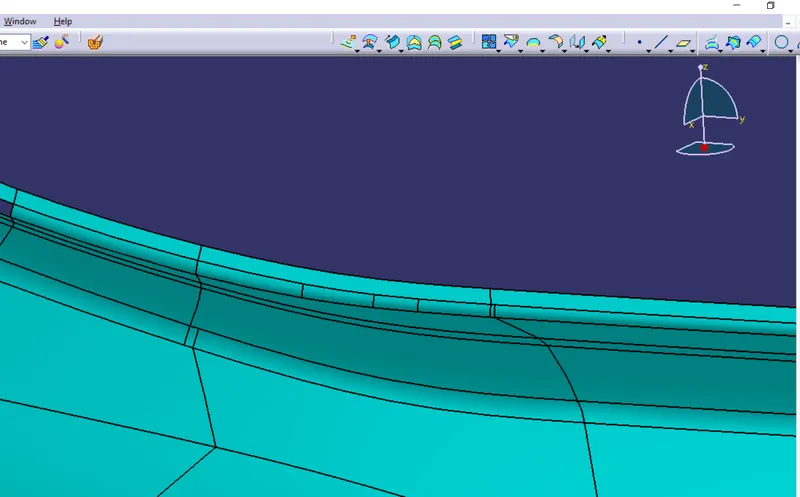
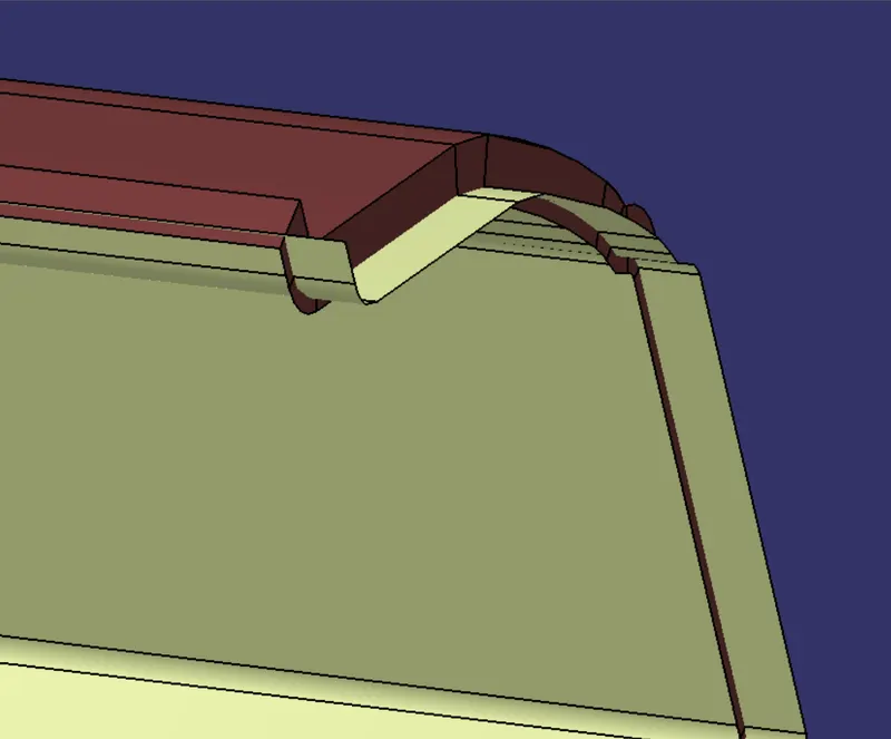
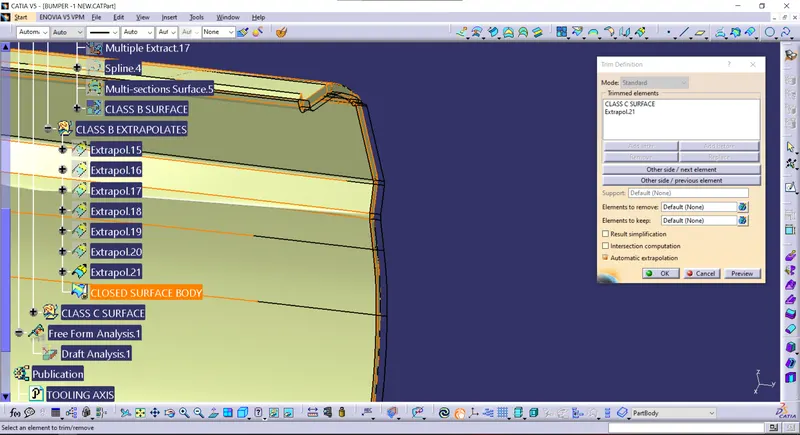
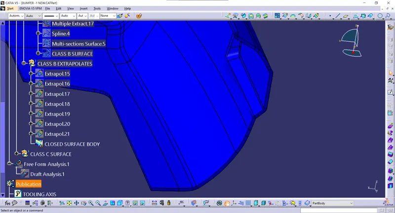
Now, unhide the class B and class C surfaces. Check whether all the sides of class B and Class C surfaces are intersecting properly with each other, to get a closed surface by trimming class B and class C surfaces. If the class B and class C sides are not intersected properly, we need to extrapolate the sides of the class B surface which are not intersecting with the class C surface. Now, check class B and class C surface boundaries whether all the sides are intersecting or not with each other. Once the surfaces are intersecting properly trim them together to get a closed surface.
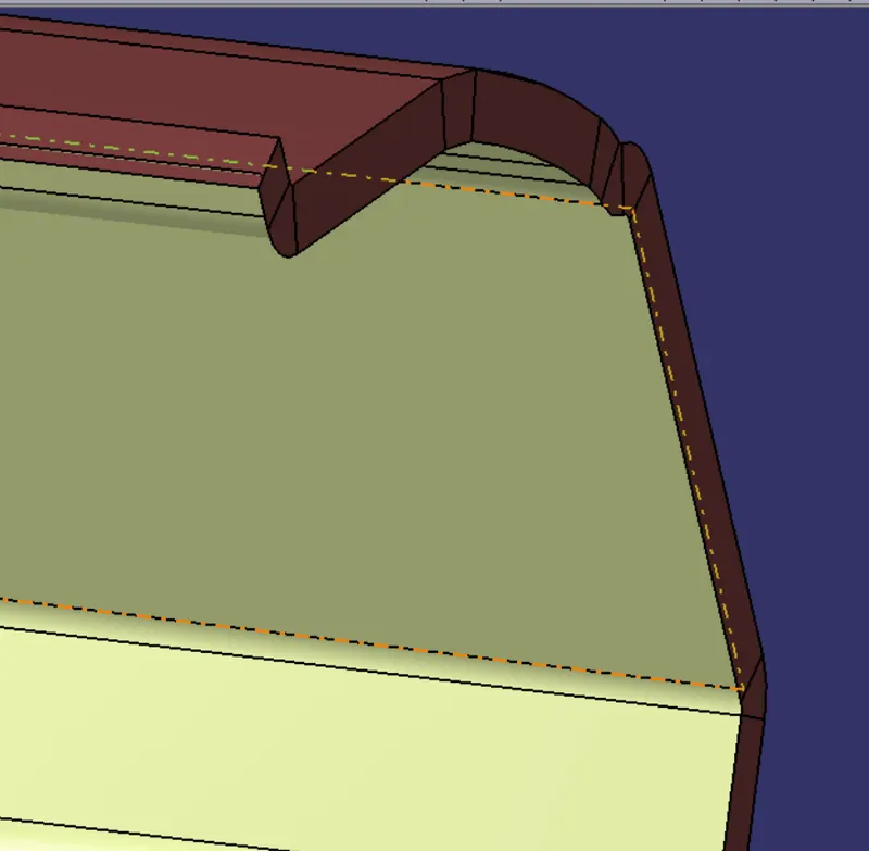
In the above-given image, the sides are not intersected properly. I extrapolated the surfaces which are not properly intersected with each other like above.
The below-given image represents the sides which are extrapolated until the surfaces are intersected.
CLOSED SURFACE
Trim
PART BODY:
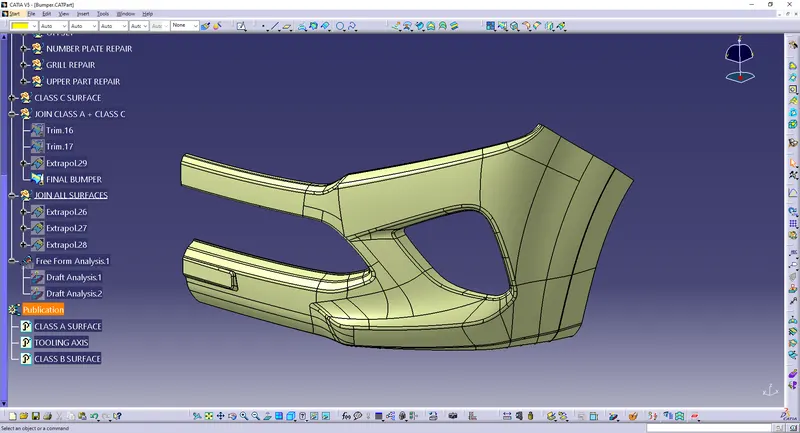
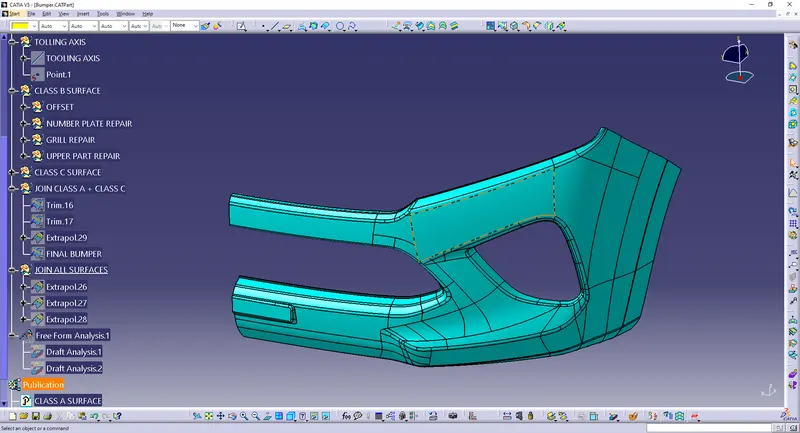
To create the solid part body from the closed surface, I used the closed surface command in the part workbench.
DRAFT ANALYSIS:
After creating a solid body from the closed surface I performed a draft analysis on it, to check the draft angle of the solid body.
Conclusion
1. Class A, Class B and Class C surfaces are created following standards of automotive industry using Catia V5 software.
2. Draft analysis was performed on the Bumper and it was observed that draft was under permissible limit for the manufacturing of the component using injection moulding process.