Week 9 - Project - A pillar Design with Master Section
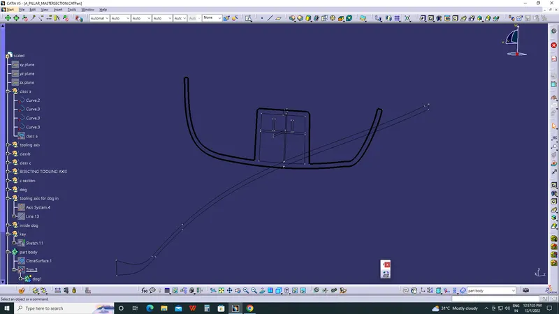
1] Master Section
- Master sections are the guides for design requirements that decide the component packaging after technical (Styling, Concept, or Class-A) surfaces. Creating this master section should need 5 to 6 years of experience.
- This helps you to decide the feasibility, clearance, packaging, and fixation strategy before working it on a 3D. We have a master section.
2] DRAFT ANALYSIS
- For molded or cast parts, the draft angle is the amount of taper perpendicular to the parting line. It is measurable in degrees. Because plastic shrinks and sticks on molding surfaces as it cools, we draft the walls of the plastic part so that it ejects or breaks free from the molding surfaces more easily and without dragging. To reduce the risk of damage to the parts and ensure ejection, a functional injection molding part must have drafts on both the cavity and core sides.
Nominal values for Draft angles
- 3 Degrees is a nominal draft angle.
- some times we have to go with a range in between 0.5 to 3
Importance of Draft in injection molding
- Reduces the possibility of part damage due to friction during the release.
- Reduces mold wear and tear.
- Ensures a uniform, smooth, unscratched finish.
- Ensures the integrity and uniformity of other surface finishes and textures.
- Reduces overall cooling time by reducing or eliminating the need for unusual ejection setups.
Steps followed for Draft Analysis
- The created part must be changed to the materiall mode in the display frame.
- Compass is enabled and placed in the direction of the Tooling Axis.
- The lock command is then used to fix the compass along the tooling axis.
- Colour codes are classified and Draft angle is applied.
- Running point analysis is used to display permissible draft angle.
3] TOOLING AXIS
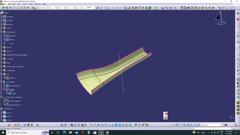
In injection molding, the Class A surface is first analyzed to determine the axis or tooling direction that separates the molds. Tooling direction is critical for plastic product design because it determines mold direction.
TOOLING AXIS CREATION
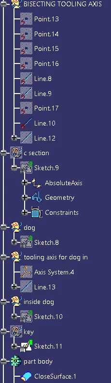
- Tooling axis here created is by selecting one of the natural axes as it clears the draft.
- Here, tooling axis is created by extracting one of the surfaces for creating a point and a new axis is created at that point.
- So, a flat face is extracted and created a point at its centre. Axis is also created at that point.
- Now, line is created using line tool and giving line type as point-direction and selected the point and direction for creating tooling axis and tooling axis is created along x direction.
4] Creation of Class B and Class C Surface
Class B
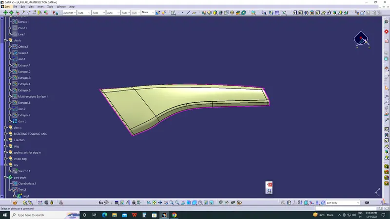
- To create the class B surface, offset the class A surface inside as per our thickness requirement (here the thickness is 3mm, so I offset the class A to 3mm inside).
- Once the offset is created, we can observe some patches on the offset surface by taking the boundary for the offset surface, those patches are formed due to the fillets on the class A surface.
- We covered the patches by using the different surface commands (multi sections surface, fill, blend) in the Generative Shape Design workbench.
Class C
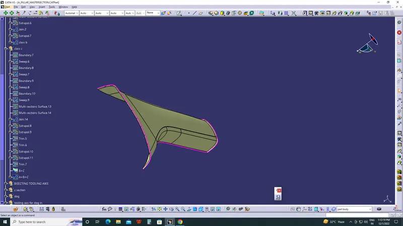
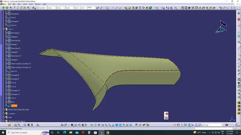
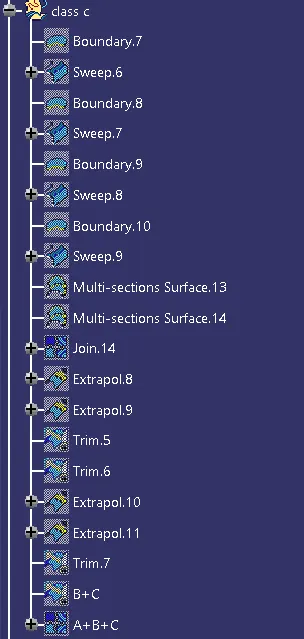
- To create the class C surface concerning the boundary of the class A surface, I used the sweep command. Initially, I extracted the boundary of the class A surface with tangent continuity, and I sweep the extracted boundary concerning the surface at 90deg (for draft angle) for 4mm to intersect properly with the class B surface.
- Once we sweep all the surface boundaries of class A, extrapolate the swept surfaces until both surfaces got intersected properly, and trim them to remove extended extrapolated surfaces to get a proper sweep boundary throughout the entire surface, including the centre hole of the bumper.
- Now, join both class A and sweep boundary to get the complete class C surface.
- Now Class A surface and Class C surface is joined.
- Now Class B surface is also trimmed with the obtained surface to get the closed surface.
- Boundary check is done to check for any open boundaries in the part. The closed surface then obtained moved to part design and close surface tool is used to obtain the part.
class b and class c
class a class b class c joined surface
5] Closed Surface
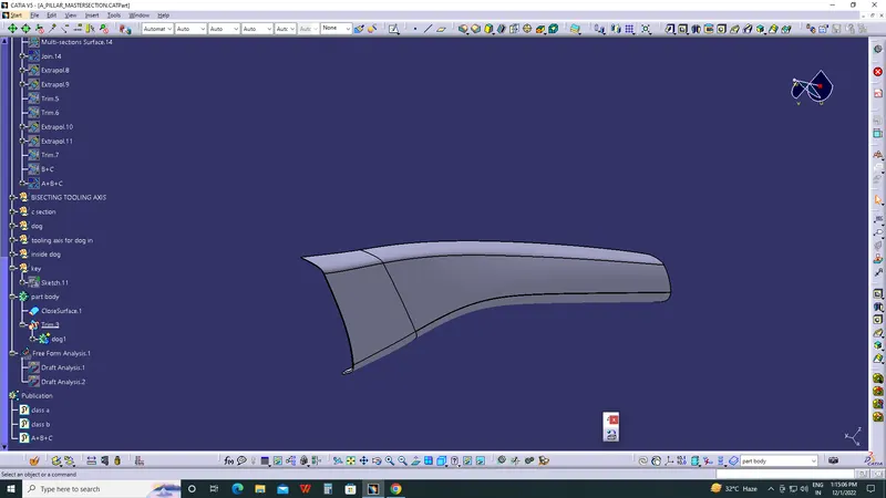
6] Creation of dog house
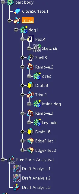
- Doghouses are created by following the design rules. For this, the sketch is created from the master section provided. It is then made into a closed body and is made into a part model.
- Shell operation is performed to get a hollow structure and then coring is done in order to avoid sink marks on the class A surface. Drafts are given for the surfaces as per design rules and proper fillets are also provided. As per the given master section, ribs and supporting features are also added to the doghouse.
- Then, the doghouse is added to the main body. All the sketches used are iso-constraint.
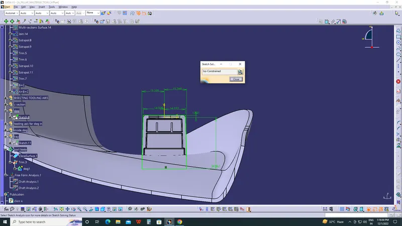
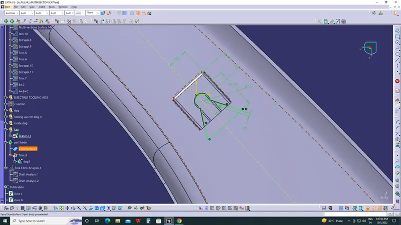
to avoid sink marck we have to make c shape cut in bottopm side of surface giving 4 mm displace ment
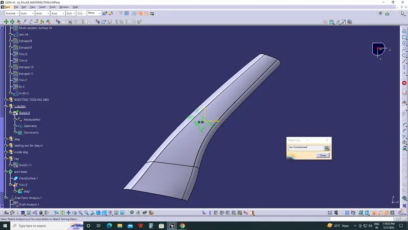
sketch the ribs present inside the dog house
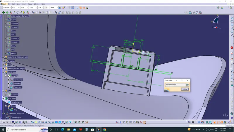
sketch of key
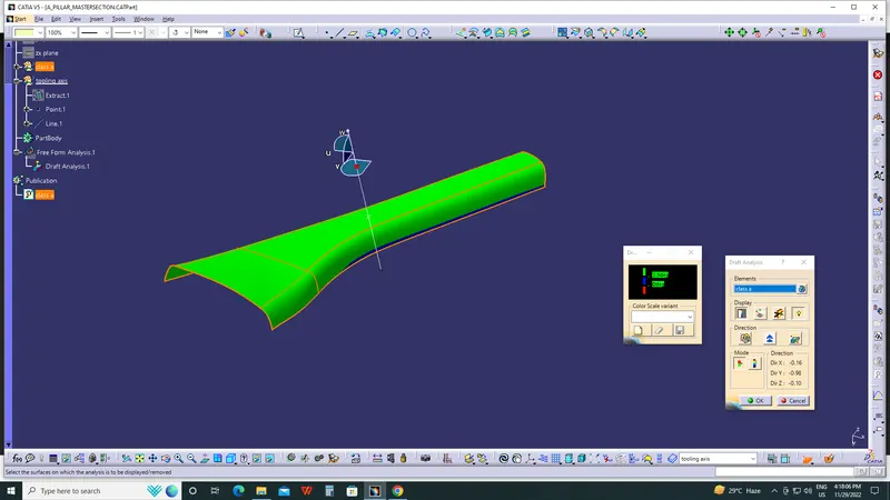
6] Screenshots of the Draft analysis report for both the given Class-A surface and the final plastic component
Procedure for performing Draft Analysis:
- Go to the Insert menu and select the Analysis option.
- Select Feature Draft Analysis.
- Select the Material option and select the surface.
- Drag the compass and place it on the tooling axis.
- Make sure that the top surface is in green color as the draft angle should not exceed 3deg.
- Click on Okay.
Class A (3 degree)
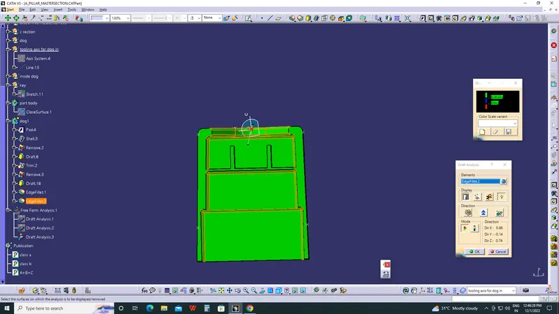
TO PERFORM DRAFT ANALYSIS OF DOG HOUSE I CREATED TOOLING AXIS WITH THE HELP OF BISECTING METHOD
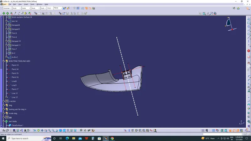
draft analysis of dog house with main tooling axis (1.5 degree)
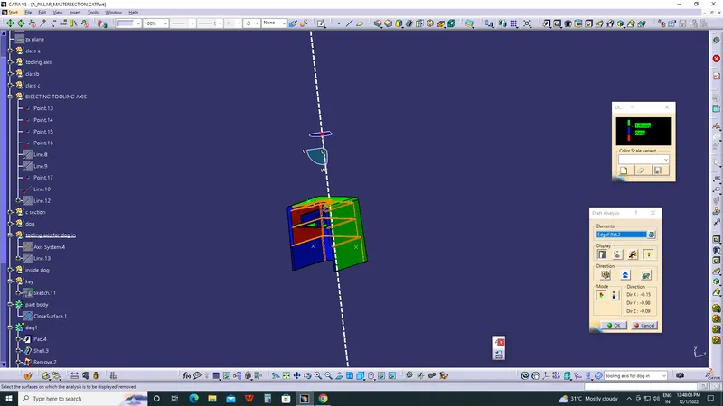
draft analysis of dog house with side core tooling axis ( 0.5 degree)
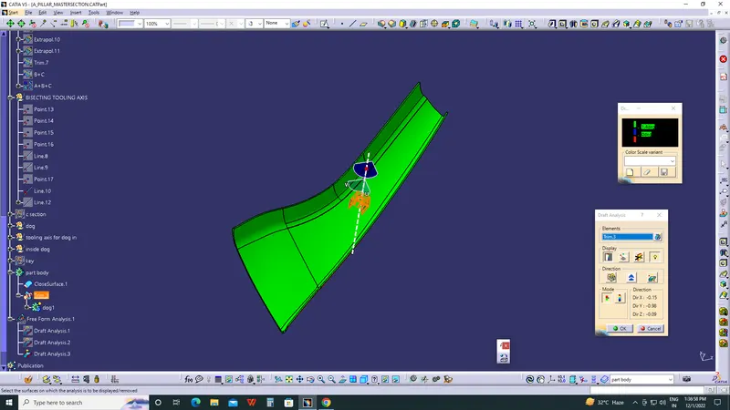
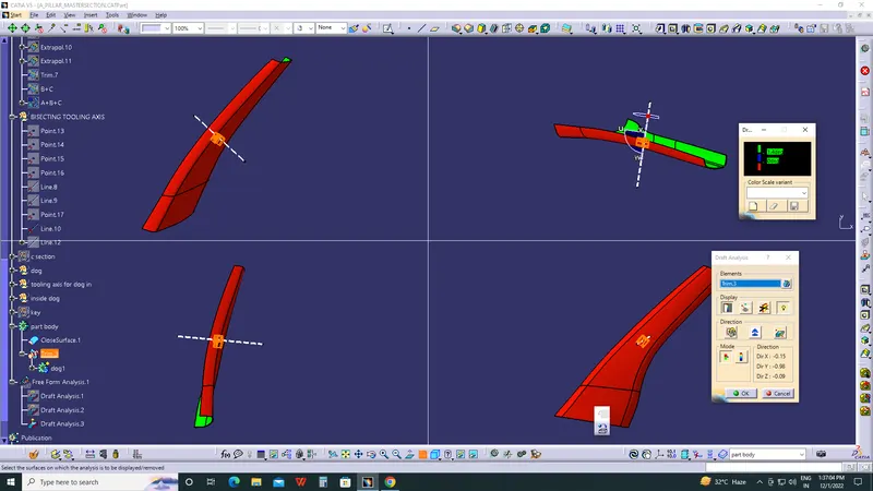
7]Screenshots of the solid model with the proper colour code of the draft angle in various orientations (Isometric, Front, Side, and Top View)
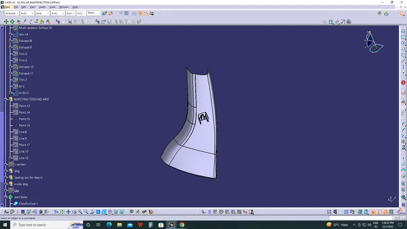
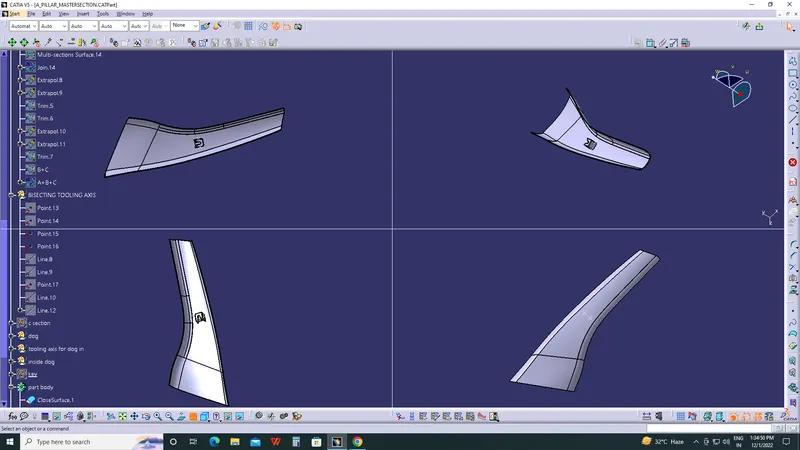
draftb analysis of whole surface body
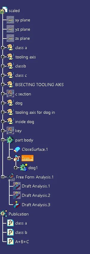
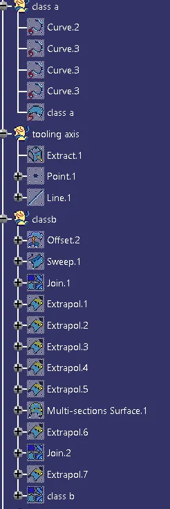
8] Screenshots of the tree structure with Geometrical sets having a proper name based on the sketches present inside of it.
9] Conclusion
- Created Tooling axis
- Created Class B and Class C surface from provided Class A surface.
- Created solid part out ofsurface modeling.
- Created engineering features from the master section provided.
- Draft analysis of Class A surface and final part is also done.