Week 9 - Project - A pillar Design with Master Section
A-Pillar Design with a master section
Aim :
To create the A-Pillar Design with the master section given as the intersection sketch with the Class A surface, create the tooling axis, and perform the Draft analysis for the final solid part.
Objective :
- Create the required Tooling axis by using the master section and bisecting method.
- Design the Class-B and Class-C surfaces and close all three surfaces.
- Design the Dog house and its internal parts as given in the Drafts and Materials section sketch.
- Draft analysis for the final solid part and side core Draft analysis.
Introduction :
CAR PILLARS
Car pillars are the vertical pillars around the car located between the glass (see diagram). Typically, A-pillars are located at the front of the vehicle on either side of the windscreen, B-pillars, or center posts are located on the side, often in between the doors, and C-pillars at the rear, either side of the rear windshield. Longer ‘estate’ cars may have D-pillars located to the rear, with B and C-pillars located to the side.
Essentially the pillars provide structural support to the roof and attachment locations for the doors. The number of pillars varies depending on the make and model of the vehicle, as does the length and width of the pillars.
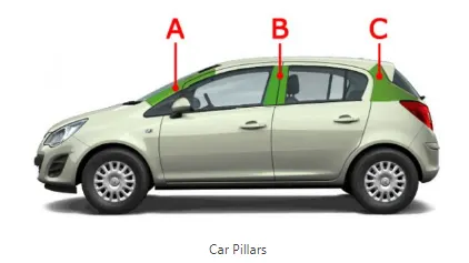
A pillar
- a strong column made of stone, metal, or wood that supports part of a building: A row of reinforced concrete pillars supports the bridge. figurative a pillar of smoke/flame. Westend61/GettyImages. pillar of sth. a very important member or part of a group, organization, system, etc.: Mrs. Maple is a pillar of the local church
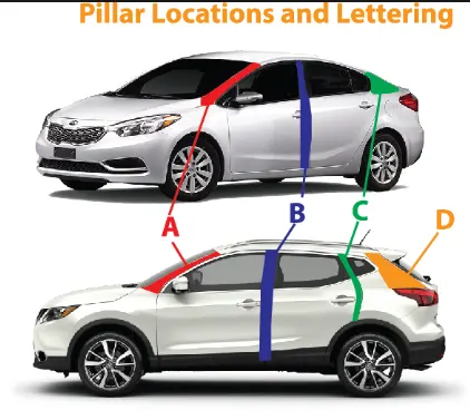
Tooling Axis :
class-A surface is first analyzed to create the tooling axis or tooling direction that molds pull apart in injection molding. Tooling direction is important for plastic product design as it decides the direction for mold separation.
Step followed for the creation of tooling axis :
- Reference point is first created on the extracted surface.
- New axis system is deployed to plot clearance lines.
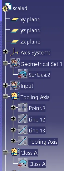
- The X-direction and Y-direction along the class-A were used to create the tooling axis.
- Graphic properties of the tooling axis were changed before publishing.
Draft Analysis :
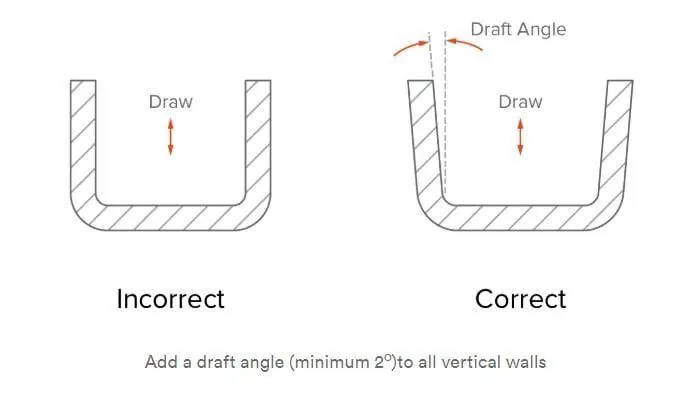
The Draft angle is the amount of taper for molded or cast parts perpendicular to the parting line. It can be measured in degrees. A functional part for injection molding has to have Drafts facing both cavity and core sides to reduce the risk of damage to the parts and ensure ejection. And also important is to overcome the vacuum forces by letting air in between the metal to the plastic for the part to release properly. Adding maintaining a decent cosmetic finish.
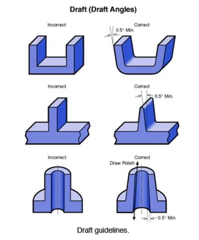
The draft should be a part of the design for manufacturing and the plastic product Designer should be aware of its need at the outset of the design process. This allows considerations for design requirements to be taken into account.
Nominal values for Draft angle :
- 3 Degrees is the nominal Draft angle.
- 7 Degrees for a textured surface.
- At a minimum of 0.5 Degrees can be manufactured by special tools. But it will increase the manufacturing cost.
Tooling Axis Creation
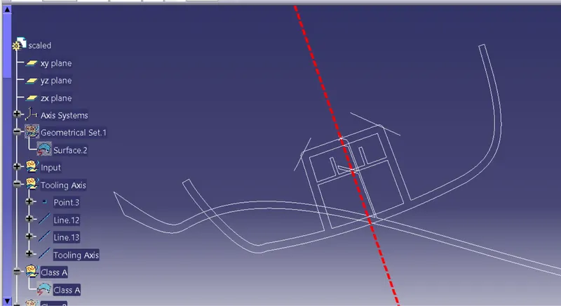
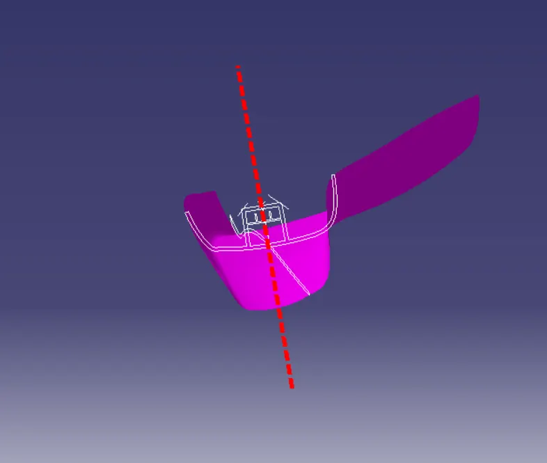
To create the tooling axis, I used the 'bisecting' line method. Initially, I created two lines on the master section by using 'point to point line', and then I created a bisecting line at the center of those two lines by using bisecting line option in the line command.
Point-to-point lines on the master section:
Final Tooling Axis
Draft analysis for class A surface:
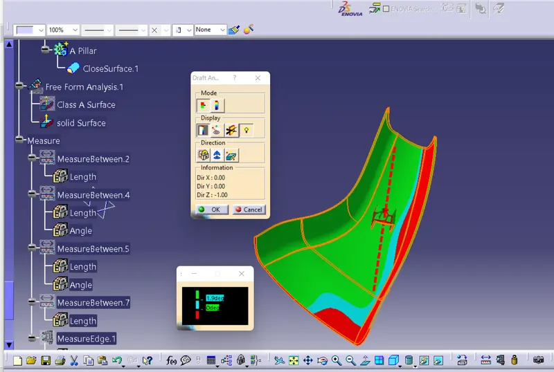
The craft analysis check is performed on the class A surface before we create the solid part from that class A surface, to check whether the given class A surface is drafted properly or not. The draft angle for a plastic component is 0.5deg to 3deg). some faces on the class A surface are not clearing with a 3deg draft angle. I reduce the draft angle gradually to clear the faces which are not clearing with 3deg
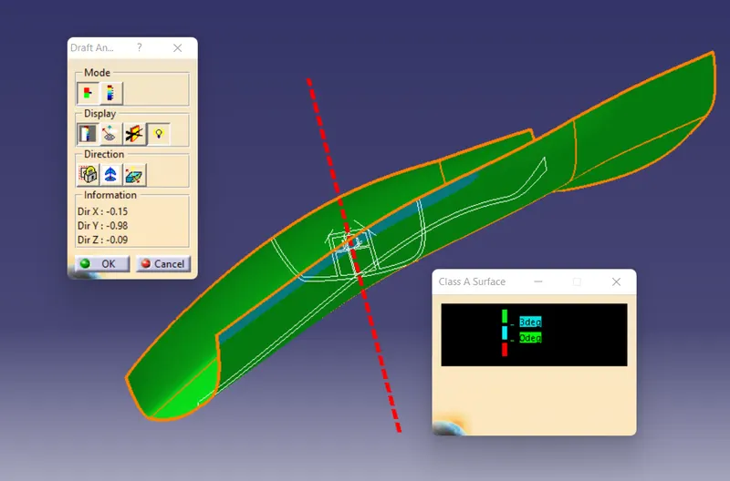
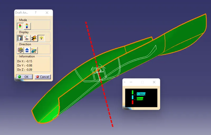
In the above-given images initially, I gave a draft angle of 3 deg and still some faces are not cleared later I gave a 2deg draft angle to check if all the faces are cleared or not. Still some faces are not cleared with 2deg also, so I reduced the draft angle to 1.9deg, with a 1.9deg draft angle all the faces in class A are cleared properly.
Class B surface creation:
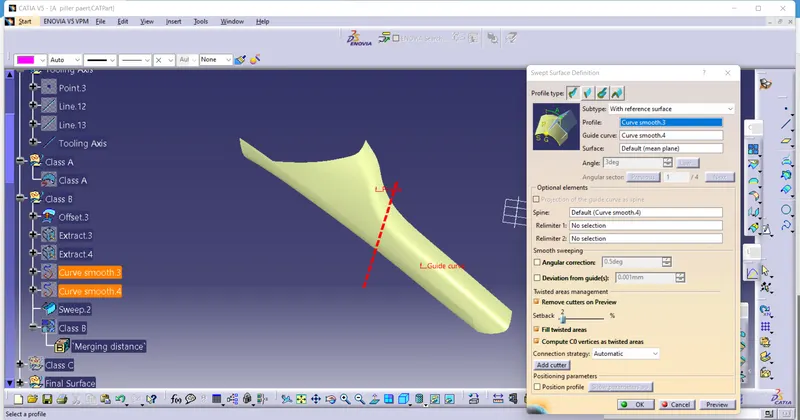
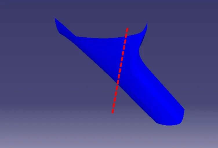
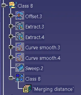
To create the class B surface initially, I measured the thickness of the master section (2.5mm). I offset the class A surface 2.5mm to the inside direction. The styling fillets on the class A surface are not offset properly, it created the patch on the offset surface. I used the sweep command to close the patch on the offset surface.
Offset by 2.5 mm
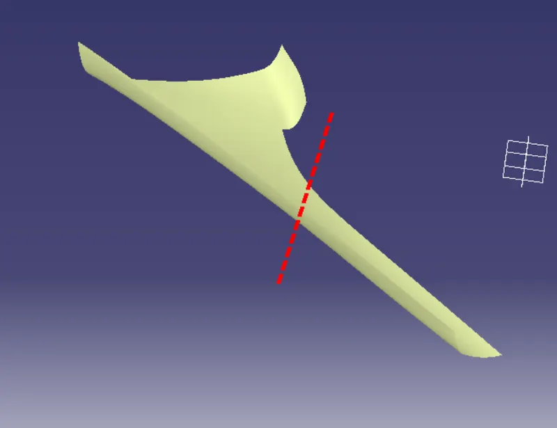
Extracted the edges of the patches, to give as a sweep command's guide curves to close the patch.
Class B surface final:
Class C surface creation:
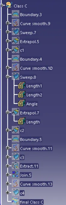
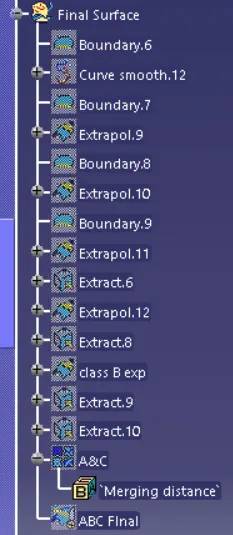
To order to create the class C surface, I used the sweep command. I sweep the class A surface edges along with referencing the surface for 4mm inside with 90deg. After the creation of the class C surface, the surface edges are needed to be extrapolated to intersect properly from all 4 sides. I trim the surfaces which extrapolated, to get the closed class C surface. I joined the class A surface and Class C surface to get a single surface of class A+C surfaces. I trim the Class B surface with class A+C surface join, to get the closed surface to create the solid bod
Class C Surface
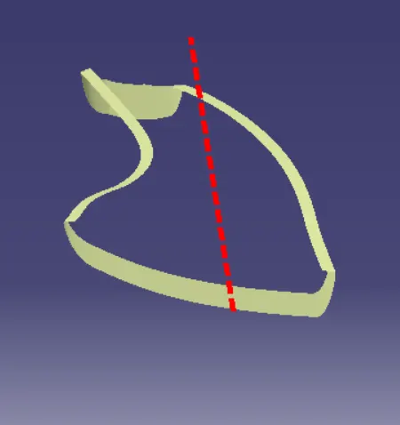
A&C Surface
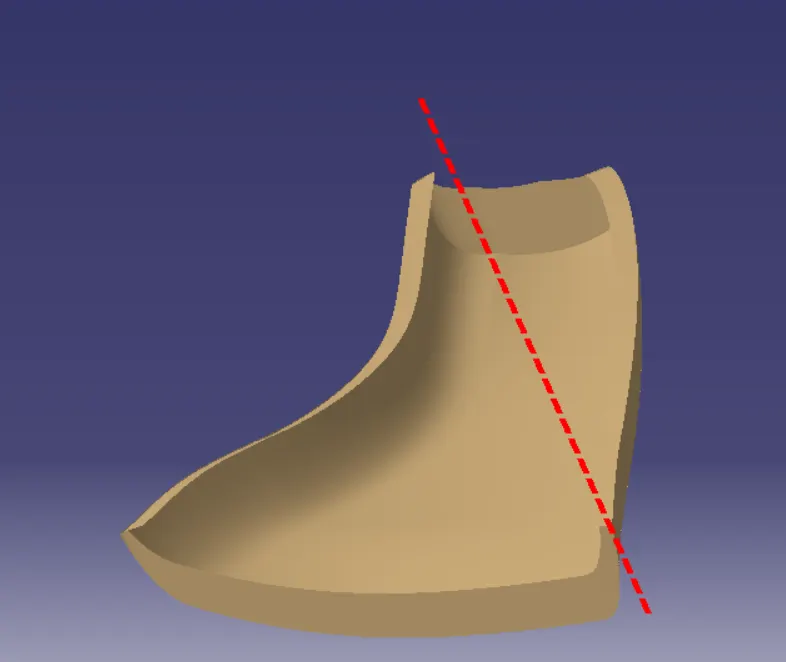
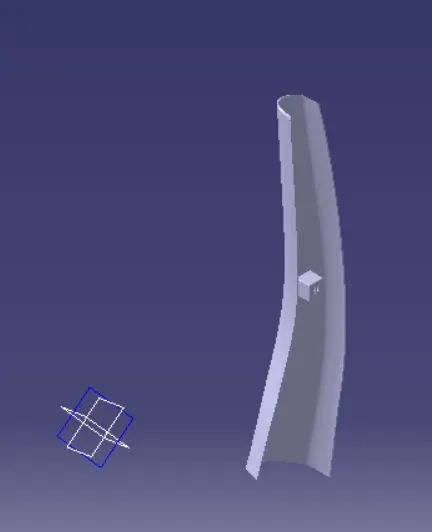
Final Part Surface
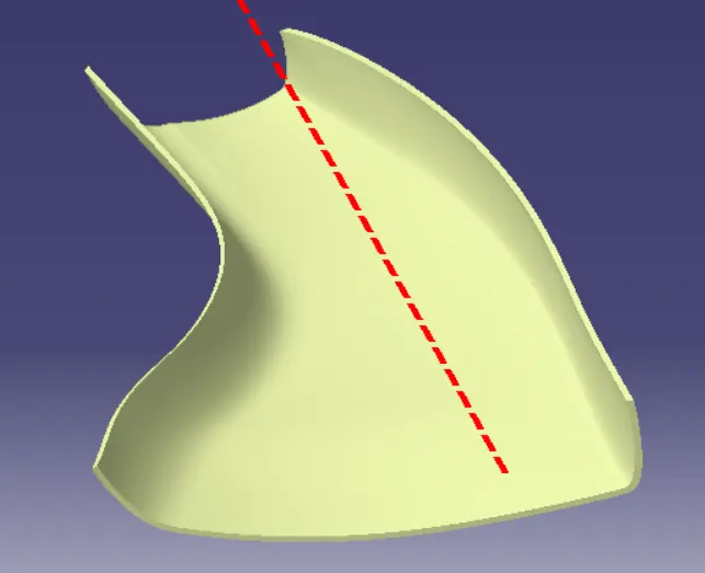
Solid part body creation:
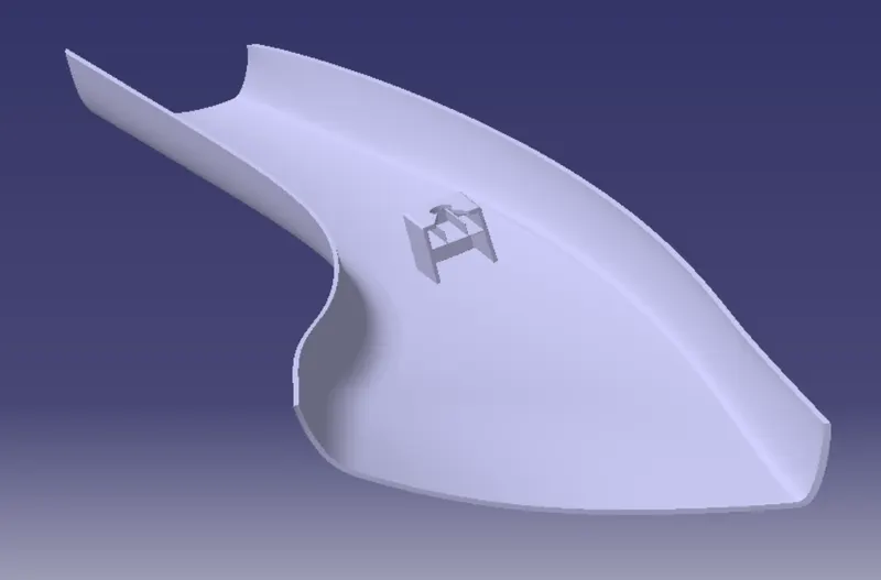
To create the solid part body, We used the closed surface command in the part workbench. we gave the closed surface as an input in the closed surface command.
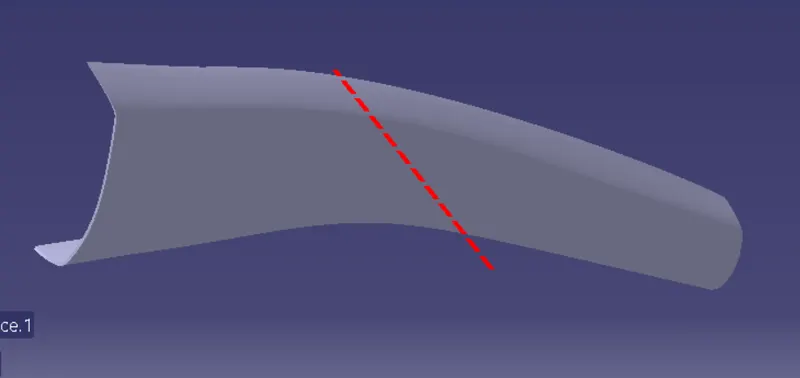
Dog House creation:
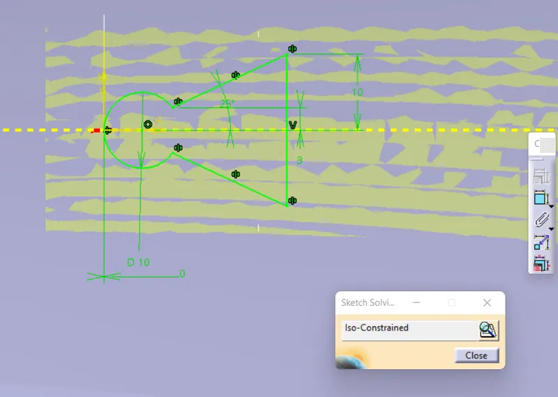
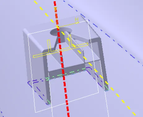
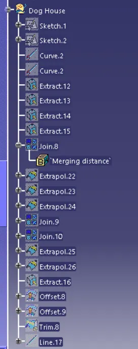
- To create the dog house on the B-side, I extracted the lines on the master section and I create a plane to extract the lines concerning the master section.
- I extracted the faces which are required to create the shell for the dog house, and I trim the surfaces with each other as per the master section dimensions.
Dog house outer shell:
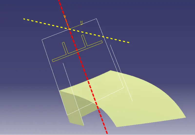
- I created the side core access, by creating a line at the centre of the back surface by creating the point.
- I thicken the shell for mm to inside. After thickening the surface, I gave deg draft to inner surfaces of the dog house.
- Now we need to give the bottom cutout for the dog house. To give the bottom cutout, I extracted the surface and offset it to 1mm outside (the bottom cutout should be 40% of the thickness of the dog house). I extract the upper surface of the dog house and offset it to 17mm bottom direction, to trim with the offset of the inner surface.
- After trimming the bottom cutout surface, I split the surface from the solid shell of the dog house. I gave a 0.5deg draft angle to the bottom area concerning to the side core axis.
- I created the rib base and ribs concerning the master section dimensions, and I gave a 0.5deg draft angle to the rib base and ribs. After drafting the rib base, I added the rib base and ribs to the dog house shell to make a single body.
- I created a sketch for the top cutout on the dog house, and I pad the sketch to the downside and removed it from the dog house part body.
Dog house top cutout sketch
Dog House
Solid part body of A pillar with Dog house:
Draft analysis for the solid part body:
The draft analysis is used to check the surface draft angel and to know whether all the surfaces are drafted properly or not.
- The draft angle for the solid body of A pillar is 3deg, some surfaces are not cleared properly with a 3deg draft angle. Previously I mentioned in the class A draft analysis report with a 1.9deg draft angle all the surfaces are cleared properly.
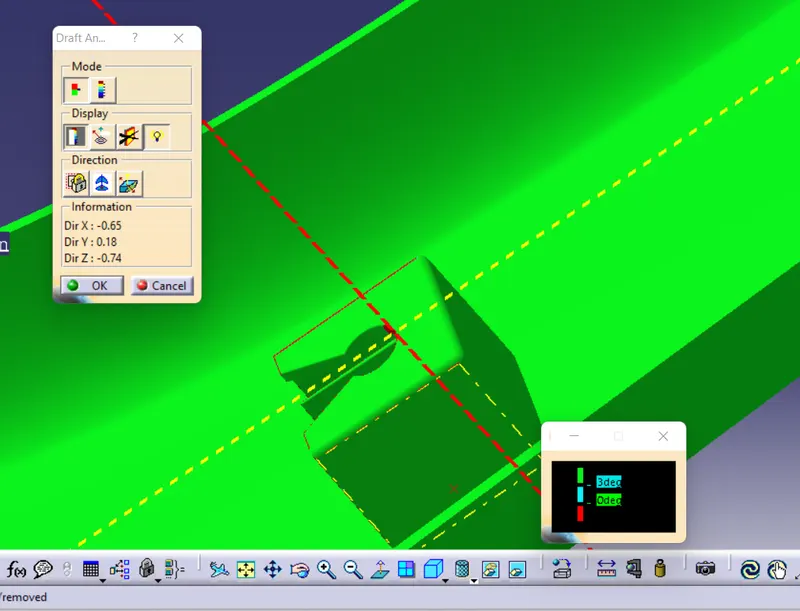
- The draft angle for the outer surface of the dog house is 1.5deg.
- The draft angle for the inner surface of the dog house is 0.5deg.
Draft Analysis For A pillar
with 3 degree Angle
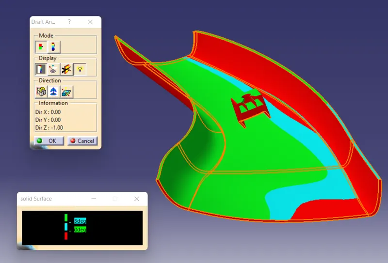
With 1.9 Degree Angle
With 0.5 degree Angle
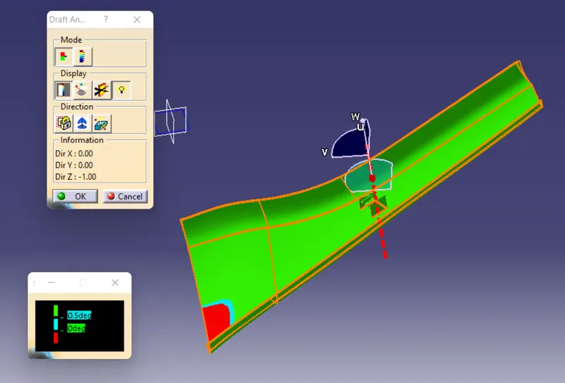
- Because of class A surface curvatures and deviations, some areas on the class C surface are not highlighted in green colour.
Draft analysis for dog house outer surface:
Drawing view
Isometric view
Front View
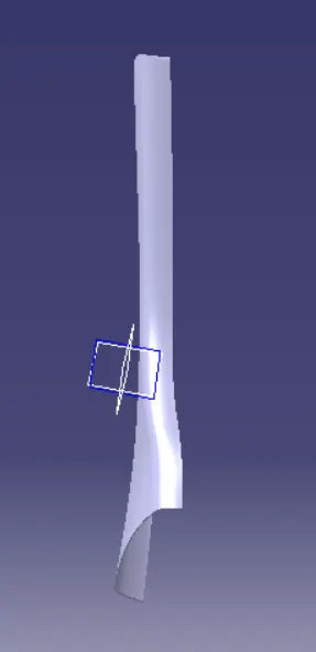
Side View
Left Side View
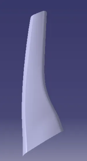
Right Side View
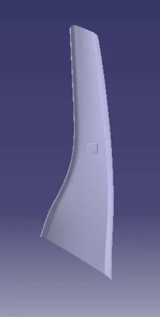
Top View

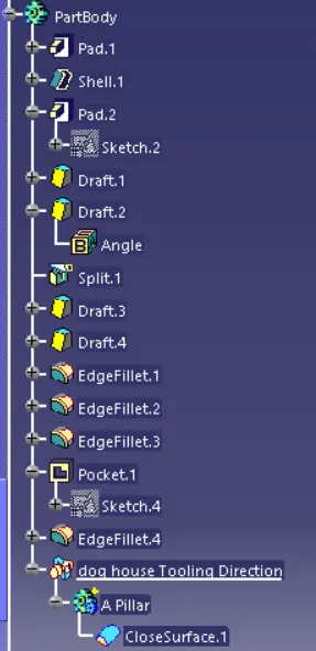
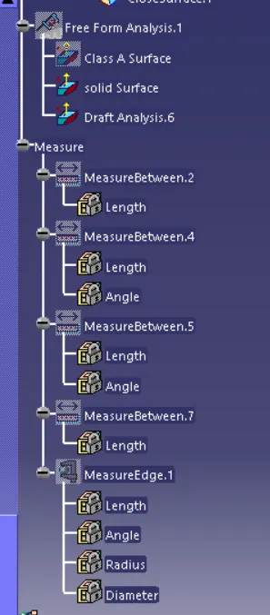
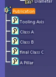
Tree Stracture
 .
.
Conclusion :
Hence the A-Pillar Design with the master section given as the intersection sketch with the Class A surface is done successfully and creating the tooling axis and performing the Draft analysis for the final solid part is also done successfully. From the Draft analysis for the class A surface some areas in a minimum draft angle of 1.9 Degrees so we need to correct it Class A surface itself by informing the Class-A surface creating team.