Week 9 - Project - A pillar Design with Master Section
PROCEDURE FOR DESIGNING A PILLAR COMPONENT :-

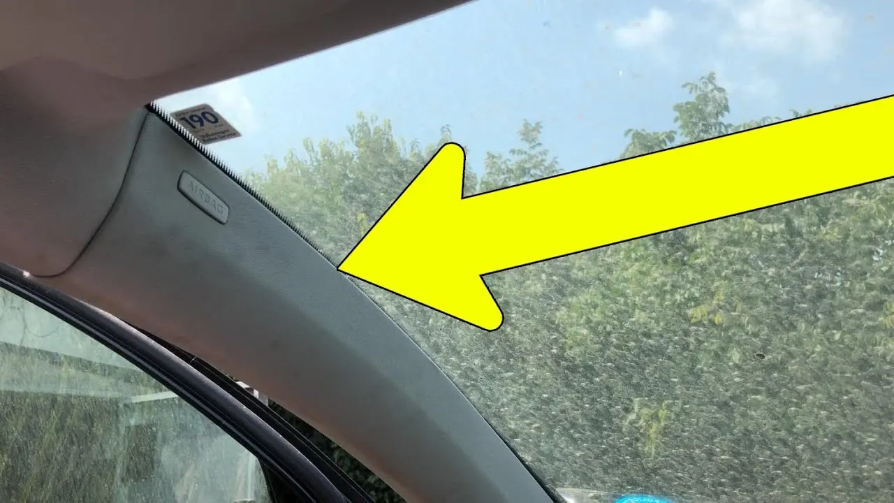
Class A surface: Class A surface is a Styling surface or aesthetic surface get it from the styling team. we will design the plastic component by using the Class A surface as input.
- Check all the views of the given class A surface that can help us to understand and get more understanding of the component.
- Connectivity of the class A surface that there is no gap between the component, by using joining command or boundary command we can check.
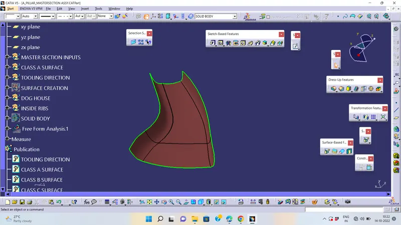
Tooling Axis :-
Class-A surface is first analyzed to create the tooling axis or tooling direction that molds pull apart in injection molding. Tooling direction is important for plastic product design as it decides direction for mold seperation.
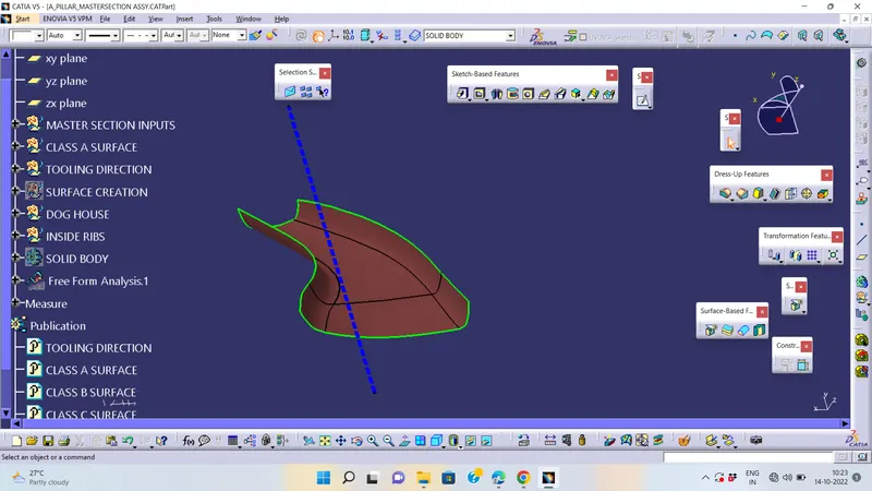
- Reference point is first created on extracted surface.
- New axis system is deployed to plot clearance lines.
- The X-direction and Y-direction along the class-A were used to create tooling axis.
- Graphic properties of tooling axis were change before publishing.
Draft Analysis :-
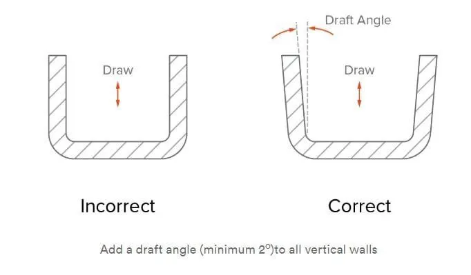
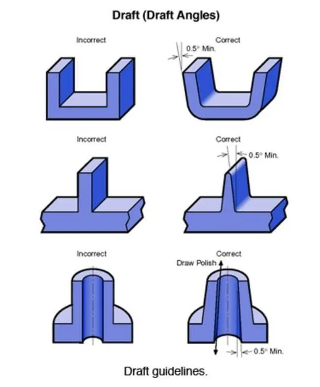
The Draft angle is the amount of taper for molded or cast parts perpendicular to the parting line. It can be measured in degrees. A functional part for injection molding has to have Drafts facing both cavity and core sides to reduce the risk of damage to the parts and ensure ejection. And also important is to overcome the vaccume forces by letting air in between the metal to the plastic for the part to relaese properly. Adding maintaining a decent cosmetic finish.
PROCUDURE FOR DRAFT ANALYSIS :-
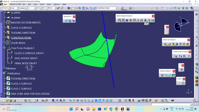
- The part created has to be changed to material mode in display frame.
- Compass is enabled and align it along with the tooling direction.
- Lock command is then classified and Draft angle is applied.
- Color codes are classified and Draft angle is applied.
- Running point analysis is used to display permissible draft angle.
CREATING CLASS B SURFACE:-
Class B surface is to be creating the engineering features and offsetting the surface of class A. Firstly we will extract surfaces by using the extract command and from the class A surface. And if there are any patches we have to make it a smooth surface and finally get the complete boundary.
CREATING CLASS C SURFACE:-
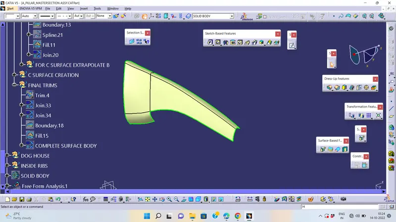
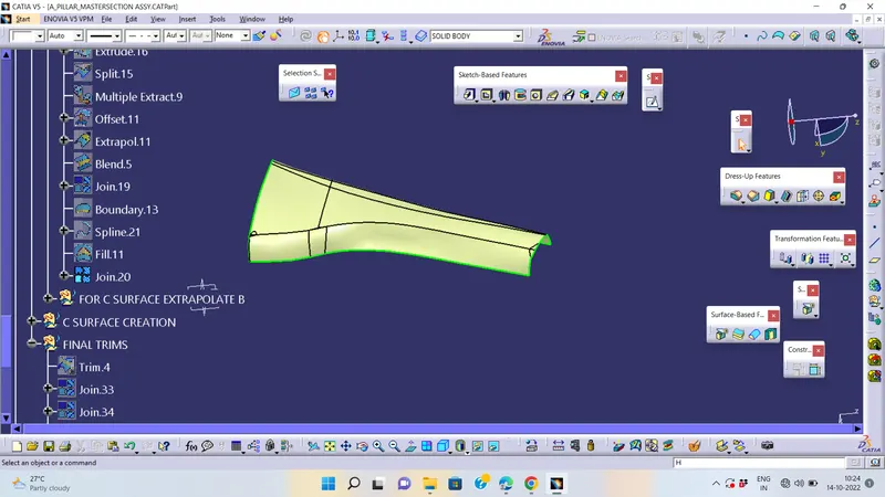
Class C surface is connected the Class A and Class B, For the class C surface, we need to create the entire boundary of the component by using the boundary command.
And also creating the best way for the tooling direction to manufacturing easily in an effective way.By using the sweep command we can combine them and trim the surfaces so we can get the completed closed surface body and draft angle given as min 3 degrees.Before trimming the most important things join them all.
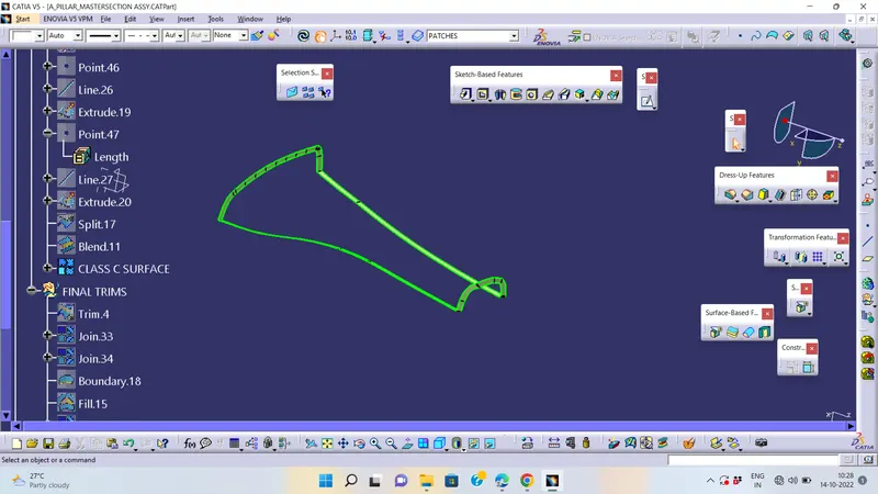
FINAL CLOSED BODY
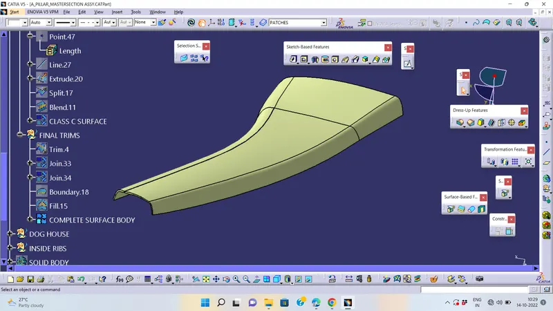
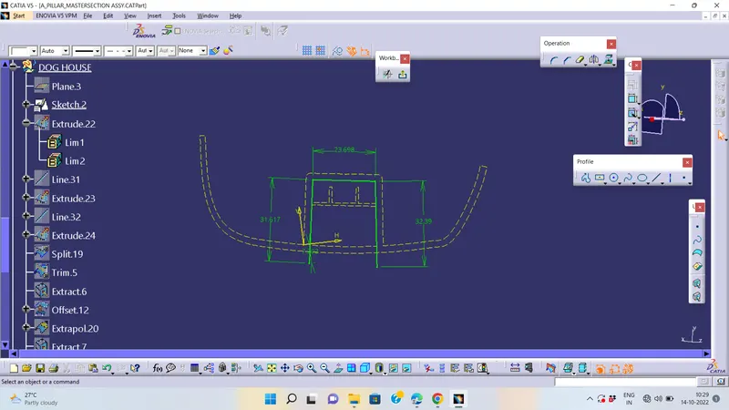
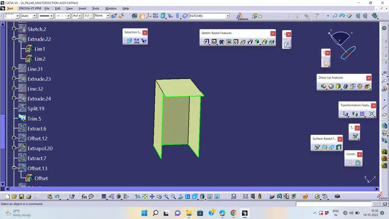
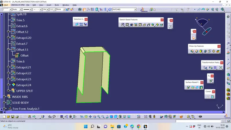
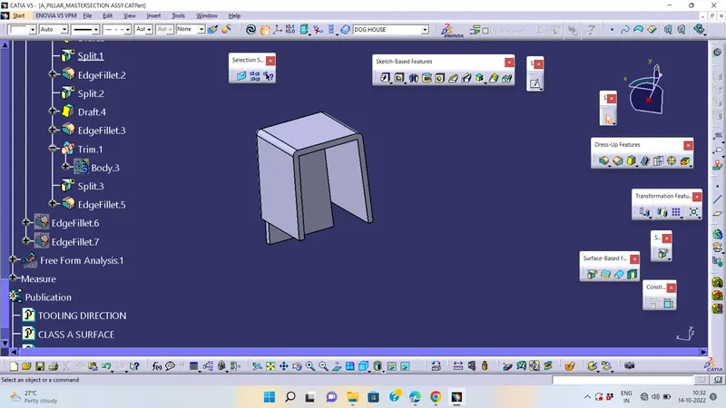
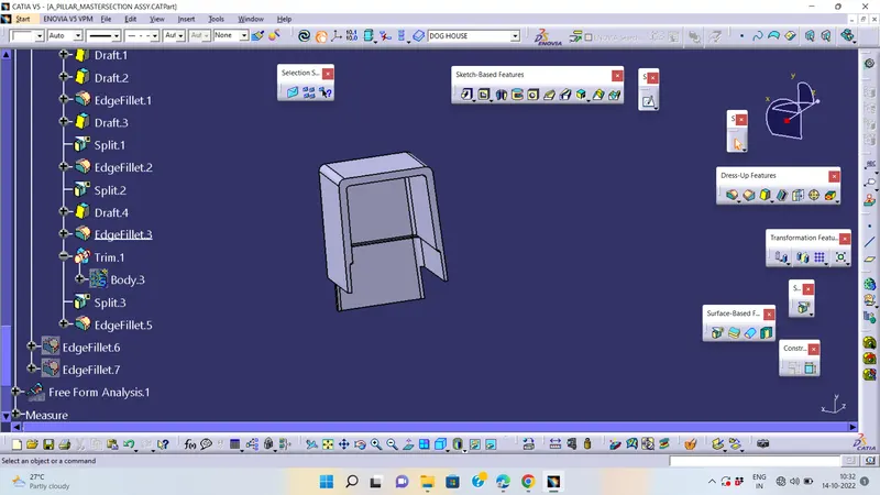
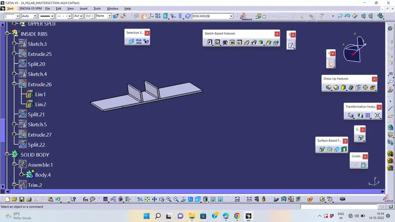
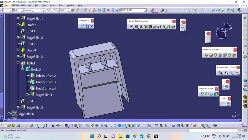
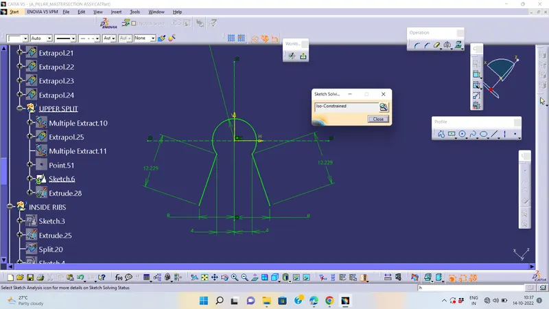
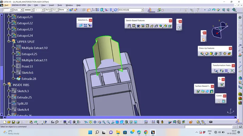
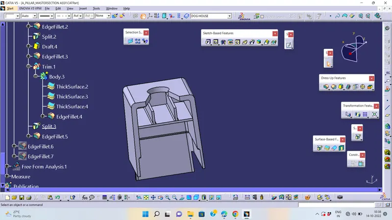
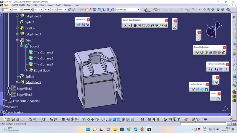
Creation of Dog House :-
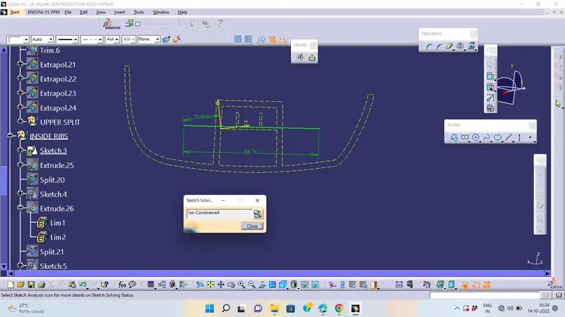
i should follow as my sketches in using master sketch only, because we have to follow anyone of SPEC MATRIX
given master sketch:-
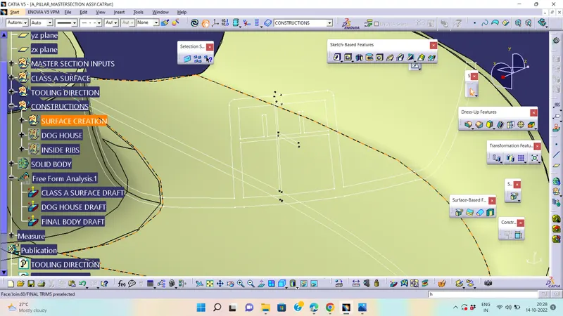
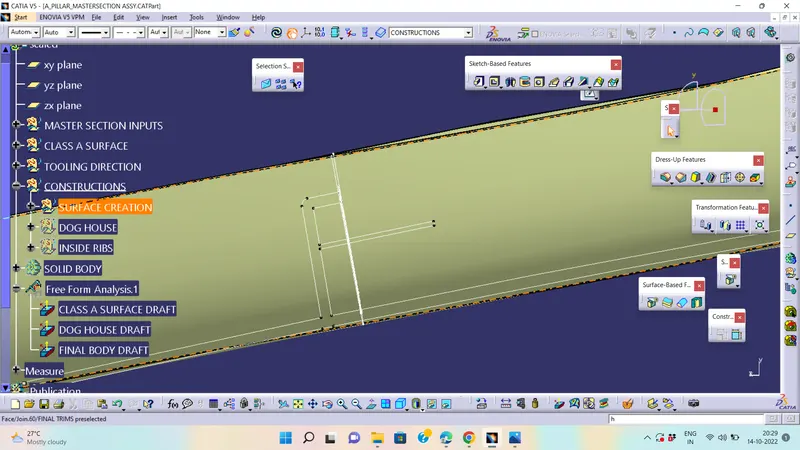
CREATING DOG HOUSE PROCEDURE :-
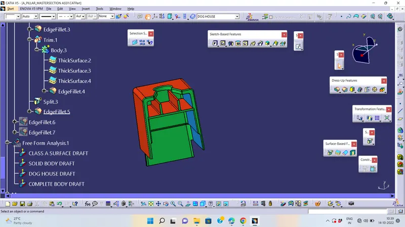
FINAL COMPONENT:-
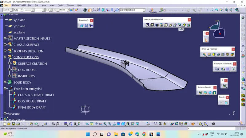
Draft analysis :-
- The part created has to be changed to material mode in display frame.
- Compass is enabled and align it along with the tooling direction.
- Lock command is then classified and Draft angle is applied.
- Color codes are classified and Draft angle is applied.
- Running point analysis is used to display permissible draft angle.
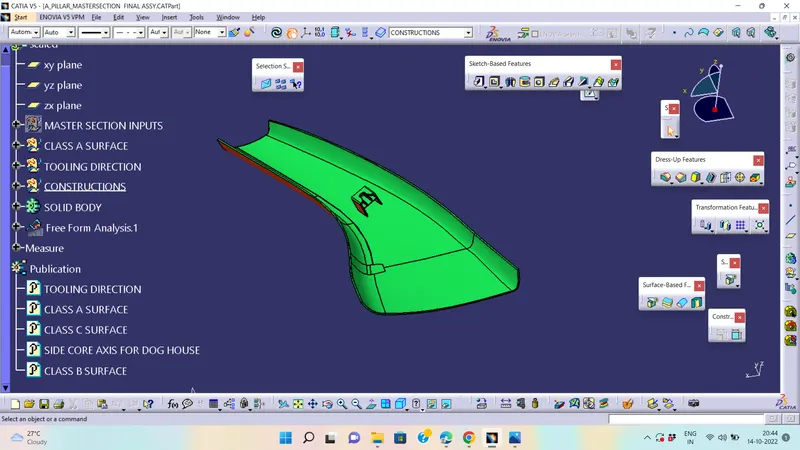
Draft Analysis For final solid part :-
Conclusion :-
Hence the A Pillar Design with the master section given as the sketch with the Class A surface is done sucessfully and create the tooling axis and perform the Draft analysis for the final solid part is also done successfully.