Week 9 - Project - A pillar Design with Master Section
The initial step is to check for any discontinuity in the class A surface model using Join or Boundary option.
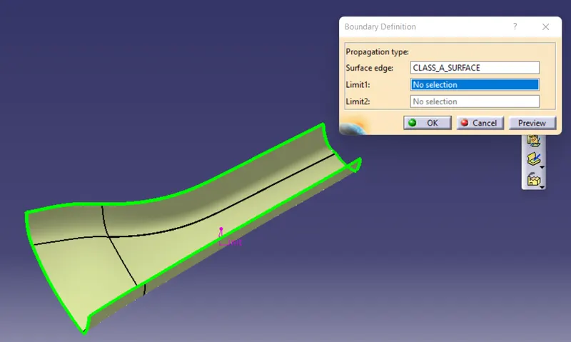
Here only the outer boundary line is found. There is no discontinuity between the surfaces.
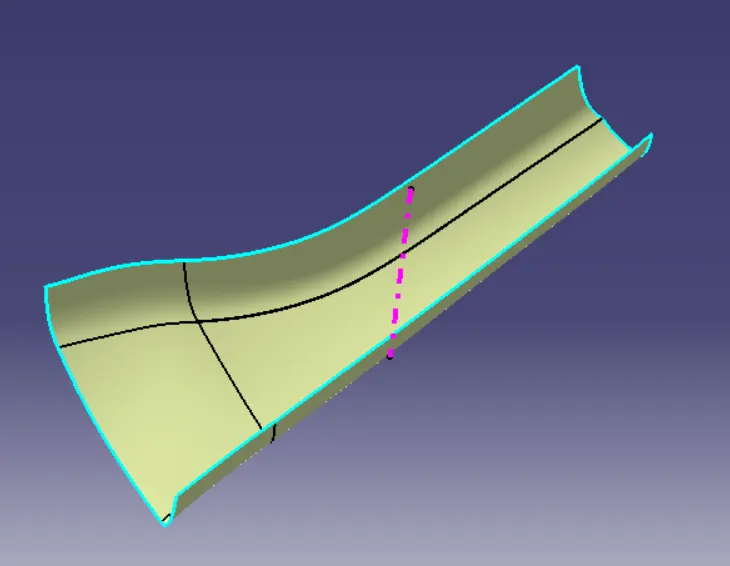
The next step is to define the tooling direction. Here the Bezel bin is more suitable for defining the tooling axis.
There is a flat face that is on the surface. Using Master geometry lines, bisecting two lines and creates an tooling axis line.
Draft analysis on Class A surface:
Draft analysis is performed on class A surface to check the draft angle's of each face.
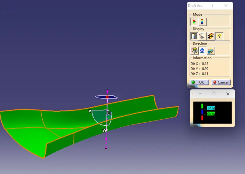
Green color on the class A surface denotes- Draft angle 3 degrees and above.
Other codes on the dialog box
Red denotes- 0-3 deg angle
Blue denotes- Less than 0 degree
Class_B_Surface_creation:
Offsetting Class A surface inward some faces were missed while offsetting. Those surfaces were created using sweep options.
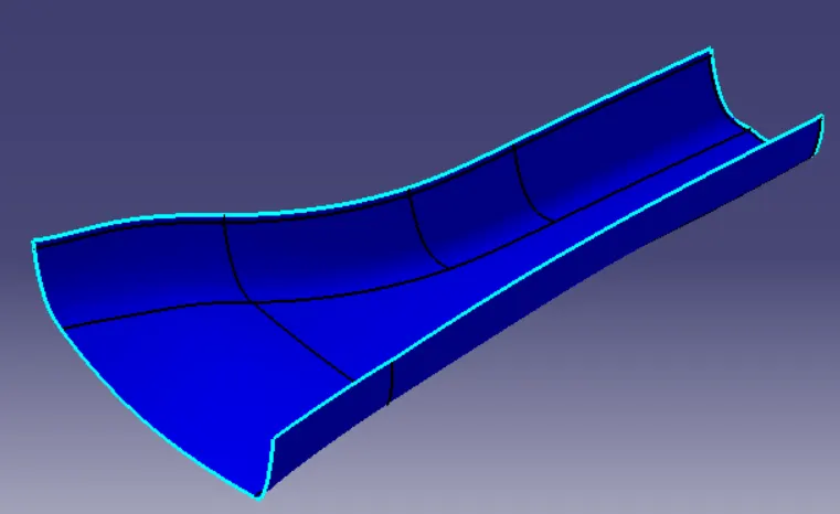
Class_C_Surface_creation:
Class C surface is used to close class A and Class B to form a closed surface.
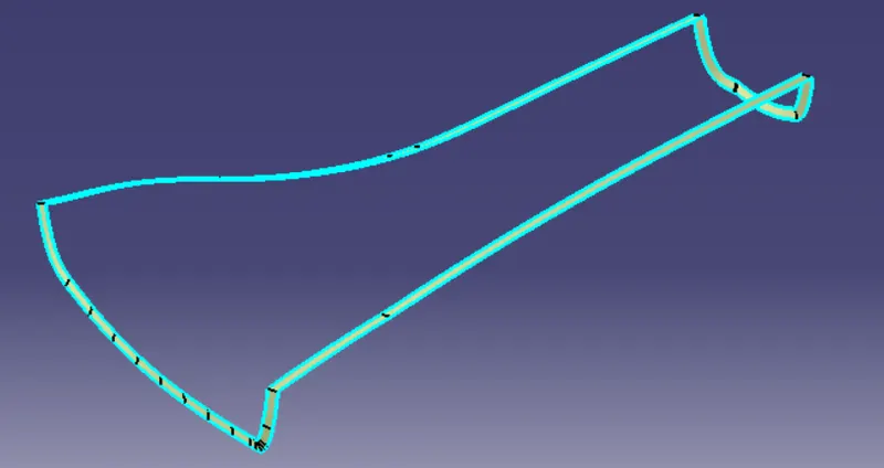
Class A+C Surface:
Joining Class A& Class C surface and trim with Class B surface to create a closed surface.
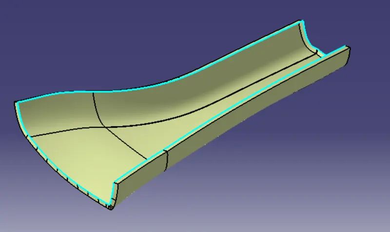
Final Closed surface
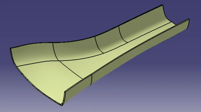
Creating a solid model:
Using the closed surface option in part modeling to form a solid model.
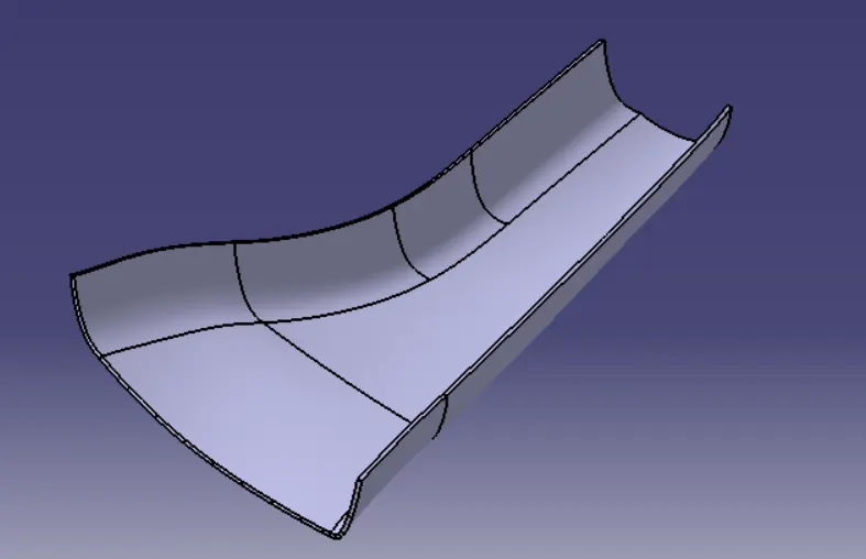
Creating B-side Features using master geometry
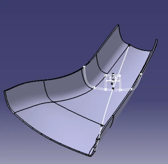
Creating the planes using master geometry to draw the profile. Mastergeometry lines show that there is a doghouse with an internal rib structure.
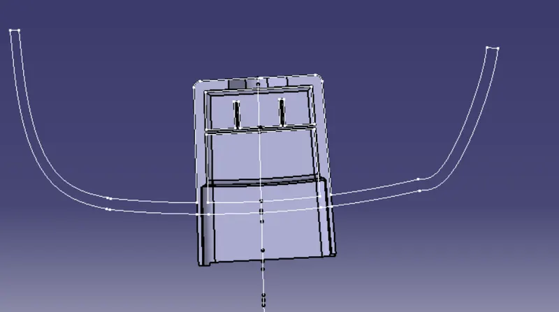
Using master geometry doghouse and inside ribs were created.
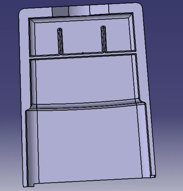
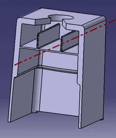
The extended bottom profile will be trimmed using a class-A surface.
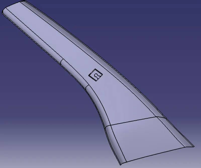
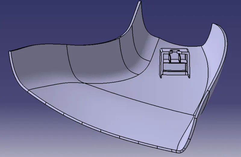
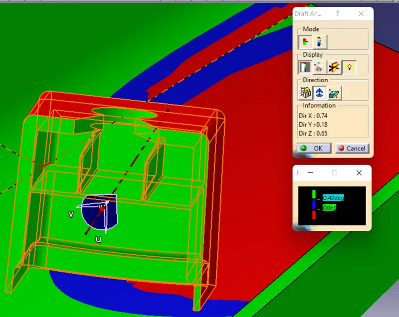
Draft analysis on the finished component:
Green color denotes- Draft angle 3 degrees and above
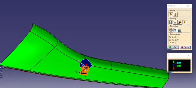
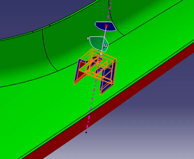
From side core tooling axis