Week -2
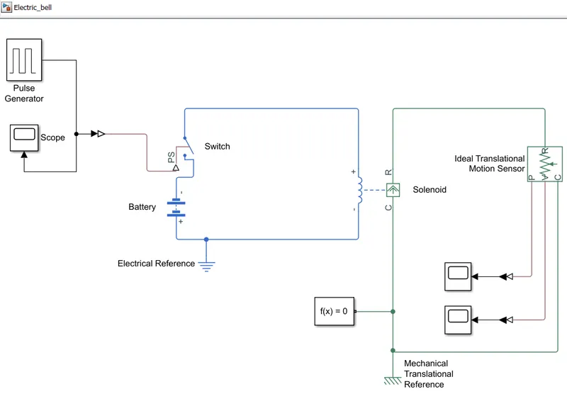
- Make a Simulink model of Doorbell using solenoid block with the following details:
Blocks used to create electric bell:
1. Pulse generator
2. Switch
3. Battery
4. Solenoid
5. Ideal translation motion sensor
Pulse Generator:
Pulse generator is used to generate rectangular or digital pulses.
Solenoid:
Solenoid is a device comprised of a coil of wire, the housing and a movable plunger(armature). When an electric current passes through this wire, a strong magnetic field is created around the coil which pulls the plunger. (Electrical energy converted into mechanical motion.

Operating condition:
Create a situation where the switch is closed for 2 seconds and then released. Observe the physical movement of the plunger.
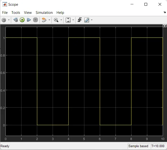
To make the switch closed for seconds and then it turn on. For that situation pulse generator is used. Using pulse generator period set assec and pulse with is 50 and time delay 0. It generate a rectangular pulse initially for 2 seconds and then off, again after 2 seconds pulses on then pulses off. To see the pulse generation a scope block is added.
The output from the pulse generator is given as input to the switch. The output from pulse generator has to be converted into physical source using Simulink-PS converter and then connected to switch. The switch is connected to a battery terminal and a solenoid.
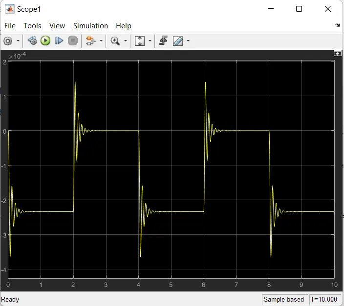
To observe the physical motion of a plunger, Ideal translation sensor is connected to the solenoid. To visualize the output from Ideal translation sensor, Scope block is connected to it. Two o/p from Ideal translation sensor. one is for the position and another one is for velocity. The output from Ideal translation sensor is converted from physical to simulink source using PS-Simulink converter and then connected to Scope block.
A solver configuration which is connected and an electrical reference is connected to electrical blocks and mechanical reference is connected to solenoid.
Working:
If the pulse is generated from pulse generator (for 2 seconds), switch turns on and the battery connection become closed so the current flows through the solenoid coil and magenetic flux is created around the coil. Due to magnetic flux it pulls the plunger for 2 seconds. After that the pulse generator switches off. After 2 seconds again generate pulses, the cycle repeats.
2. Use a thermistor to sense the temperature of a heater & turn on or turn off the fan:
Thermistor:
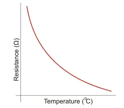
Thermistor or Thermal reisitor is a type of resistor whose electrical resistance varies with changes in temperature. Thermistors are passive components in circuit.
Types of Thermistors:
1. Negatice Temperature Coefficient (NTC)
When Temperature increases, resistance decreases and the temperature decreases, resistance increases. NTC is most common type of resistor.
2. Positive Temperature Coefficient (PTC)
When temperature increases, resistance also increases and if the temperature decreases, resistance also decreases.
Working condition:
Time period 0-10 seconds- 20 deg celcius
Time period 10-30 seconds- 27 deg celcius
Time period 30-50 seconds- 23 deg celcius
Fan should be on only if the temperature is above 25 deg celcius otherwise fan should be in off condition.
Blocks used to create the model:
1. Signal Builder
2. Controlled Temperature source
3. Thermistor
4. Voltage sensor
5. resistor
6. Battery
7. Switch
8. Controlled voltage source
9. Dc motor
10. Ideal rotational motion sensor
11. Scope block
12. Solver
13. Simulink-PS solver
14. PS-Simulink Solver
15. Thermal reference
16. Electrical reference
17. Mechanical rotational reference
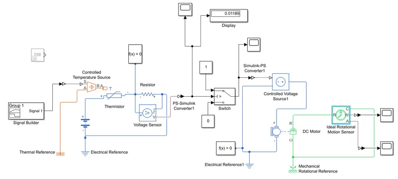
Signal builder which is used to create the temperature source conditions like from 0-10 seconds- 20 deg celcius (293K), 10-30 seconds- 27 deg celcius (300), 30-50 seconds- 23 deg celcius (296). Themistor sense the temperature only in kelvin so the celcius values are converted into kelvin by adding 273(i.e 0 deg= 273K).
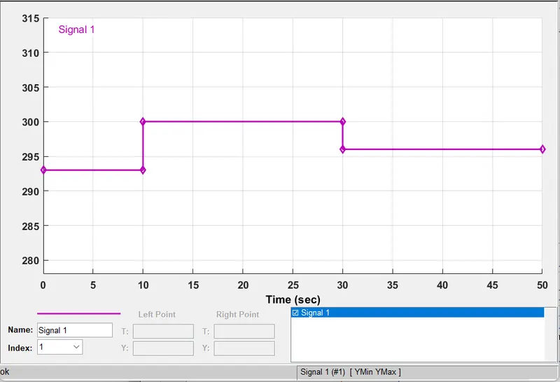
Output from Signal builder changed into physical signal using Simulink-PS converter. That physical signal is given as a input to controlled temperature source. This output is given to Thermistor.
Thermister is connected with Resistor & Voltage sensor & Battery. Due to increase in themperature there should be an voltage drop will cause. To find that voltage, Voltage sensor is used. To find the voltage drop at 25 deg celcius(i.e 298K) a model is created with constant block having 298K value for finding the voltage drop. The voltage drop value is displayed in display block (0.01189). That is the threshold value.
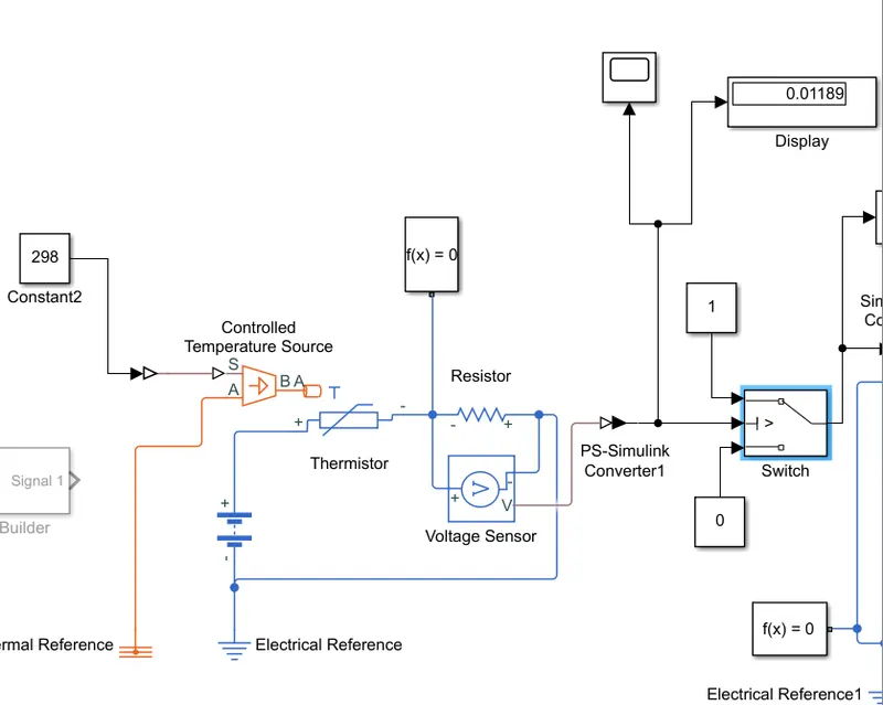
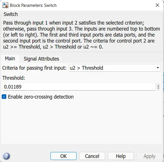
Now the output from voltage sensor is converted as Physical to Simulink signal using PS-Simulink converter and then it is given as input to switch. In switch set the Threshold value 0.01189. Two constant blocks having 1 & 0 are attached to switch.
Output of the switch is conerted from Simulink to physical using Simulink-PS converter and connected to a Controlled Voltage Source & DC motor. DC motor output is connected to Ideal Rotational Motion Sensor to sense the rotation of dc motor for the applied inputs Ideal rotational motion sensor shows velocity and angular displacement outputs. These output graphs are viewed using Scope block. Thermal, Electrical, Mechanical rotational reference blocks are used to connect reference points. Solver configuration used to solve the model.
Working:
Temperature from signal builder goes to thermistor and there should be an voltage drop is caused due to temperature change. For 298K(25 deg celcius) voltage value is 0.01189. Only if the temperature value 298K then the voltage input agrees with switch threshold value then the dc motor turns on. Otherwise the fan remains off.
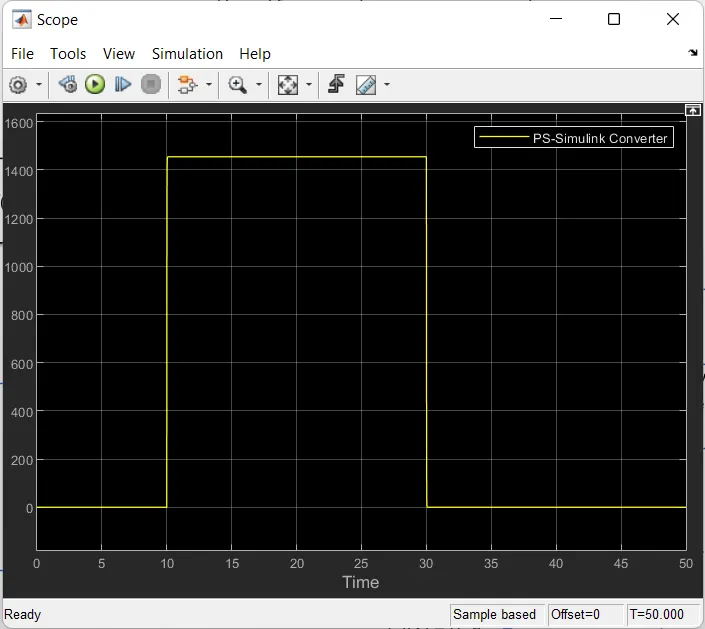
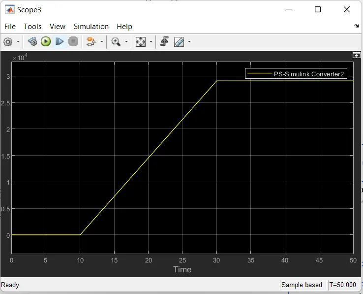
Velocity output:
Output:
The above graph shows, for 0-10 sec fan remains off, after that temperature above 25 deg celcius the fan switched on, after 30 second temperature is 3 deg celcius fan switches off.