Week 9 - Project - A pillar Design with Master Section
AIM:
- To design the A-Pillar with B-Side attachment features of the dog house and ribs through the reference of the master section.
TOOLING AXIS:
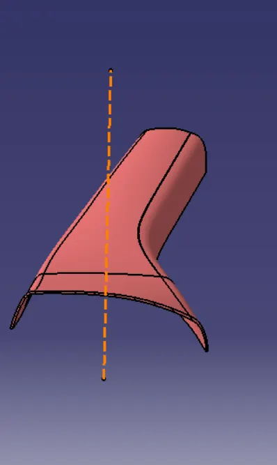
- Tooling axis is the defined axis to perform the manufacturing process within the injection molding according to its direction.
CREATION OF TOOLING AXIS:
- First of all analyze the given input surface to see which direction is suitable for creating the tooling axis.
- In this model we have the create the tooling axis by the reference of the master section.
- Extract the side wall of the master section and create the point between these lines using the point command.
- Create a line by using the point-direction line type option with reference to the z direction.
- Final sketched line is called as tooling axis.
DRAFT ANALYSIS:
- The analysis of the model should maintain the nominal 3-degree draft angle to the tooling axis.
- Draft analysis reveals the manufacturing feasibility of the component, whether the designed part is able to manufacture or not without maintaining the nominal draft angle.
- Draft should be given to the plastic component to reduce the wear and tear and improve the production quality and accuracy while ejecting the part from the mold cavity.
How to perform the draft analysis
1. Go to insert < analysis< feature draft analysis.
2. Align the tooling axis with a compass.
3. Click on the surface to see whether it is in permissible limit draft values or not.
4. The entire surface should be green in color.
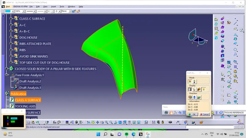
DRAFT ANALYSIS FOR CLASS A SURFACE:
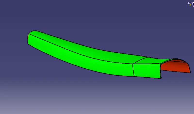
DRFAT ANALYSIS FOR CLOSED BODY OF A PILLAR:
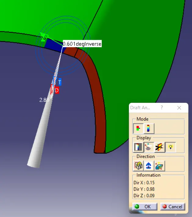
The highlighted area contains the minimum draft area of 0.601 degrees.
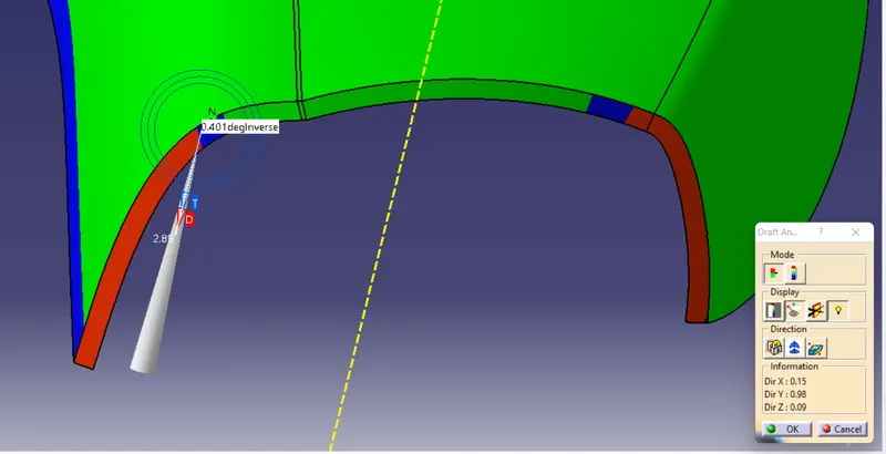
The above-highlighted area contains the minimum draft area of 0.401 degrees.
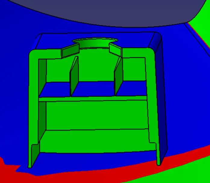
DRAFT ANALYSIS OF DOG HOUSE BY SIDE CORE AXIS:
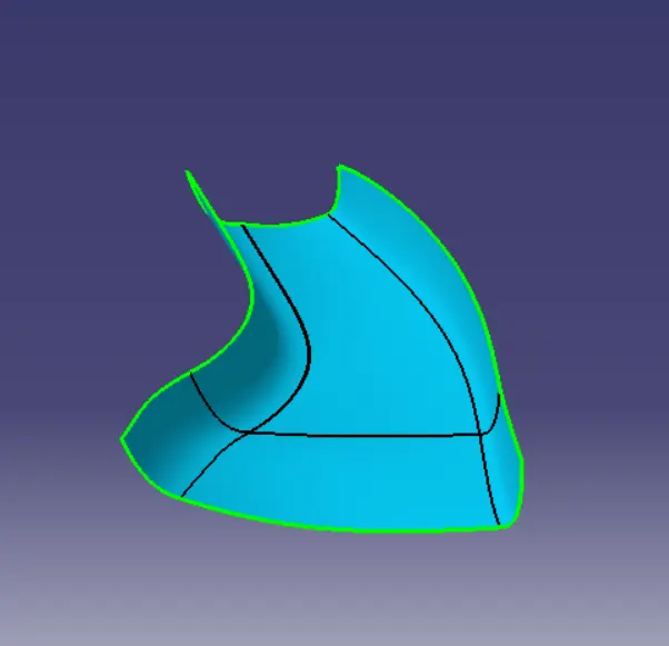
CLASS- A SURFACE:
- Class-A surface is given as an input surface by designers.
- Generally the class-A surfaces have the tangent continuity
- Class-A surface is the outermost aesthetic surface.
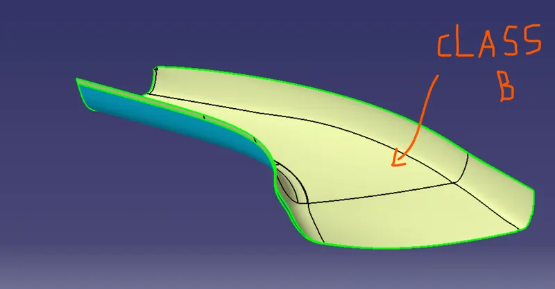
CLASS B SURFACE :
- Class B surface is an engineering surface.
- The engineering features of ribs, screw boss, dog house, heat stakes, and locators are designed on the class B surface.
- Class B surface is created by the offset of class A surface.
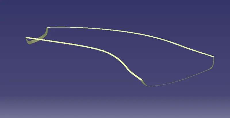
CLASS C SURFACE:
- Class C surface is the closing surface of class A and class B surfaces.
- It is the extraction of the boundary of class A surface.
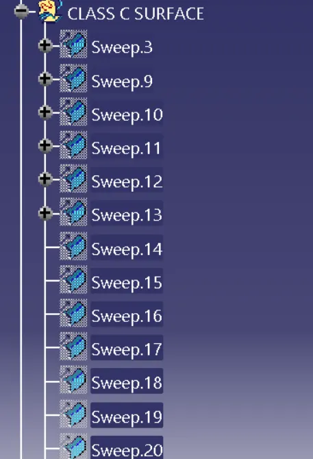
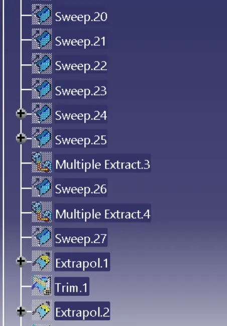
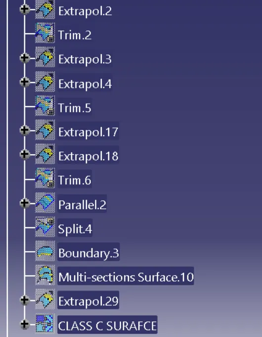
- Apply the sweep feature to create the class c surface, For guide reference click the extracted boundary and for the drafting reference option click the tooling axis and give a 3-degree draft angle.
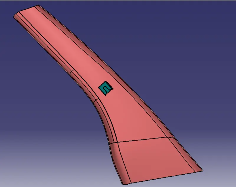
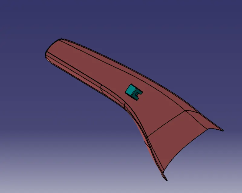
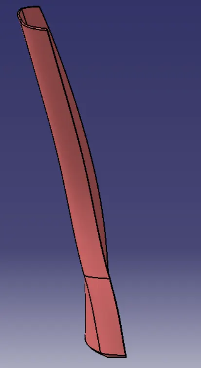
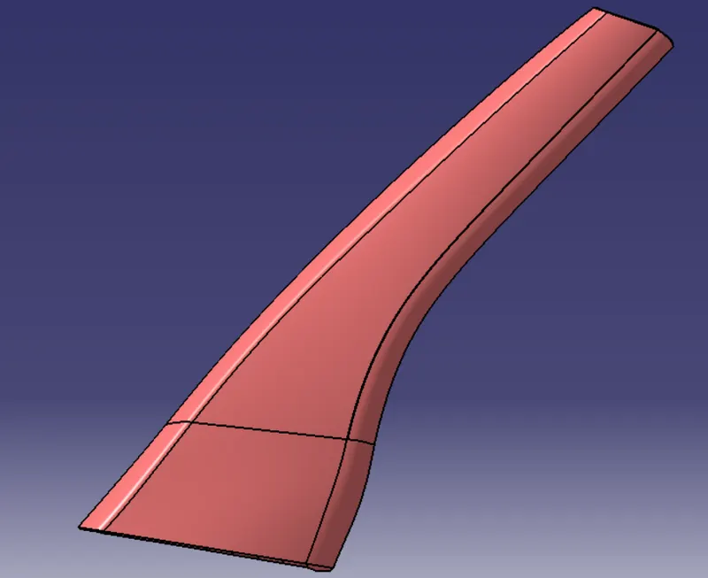
FINAL COMPONENT IMAGES:
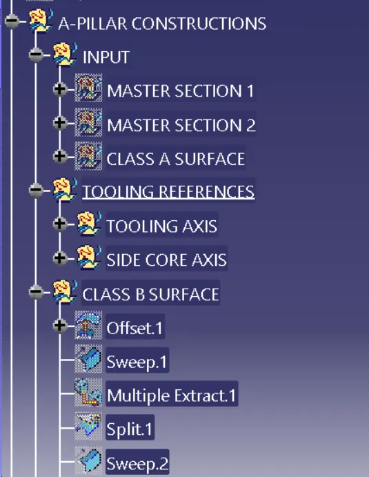
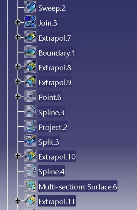
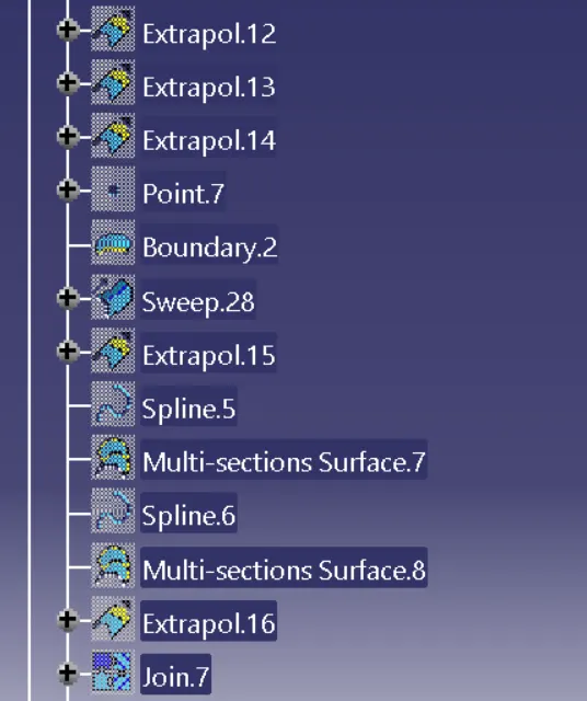
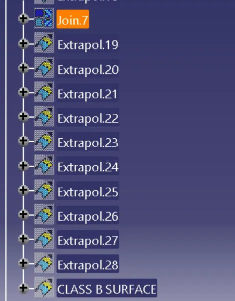
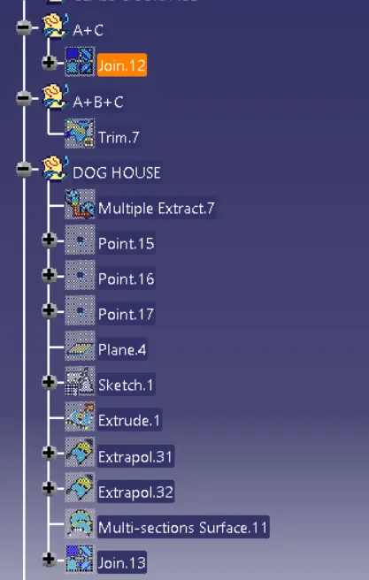
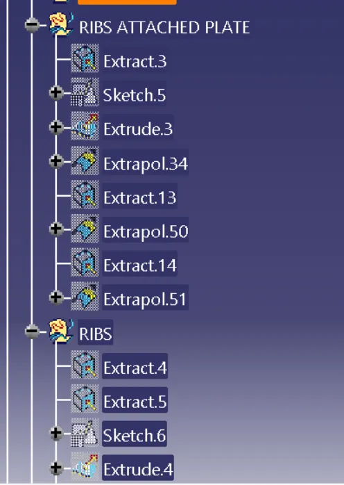
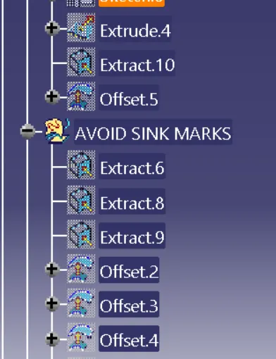
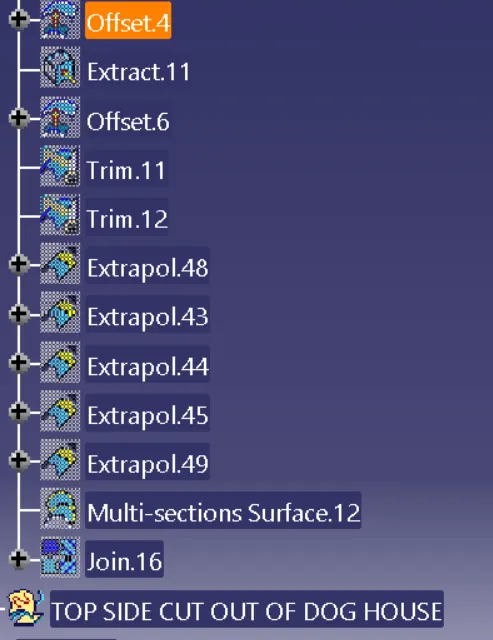
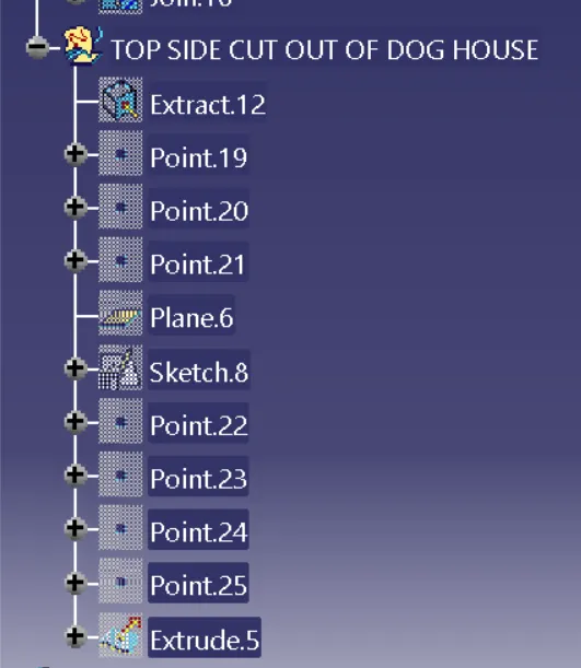
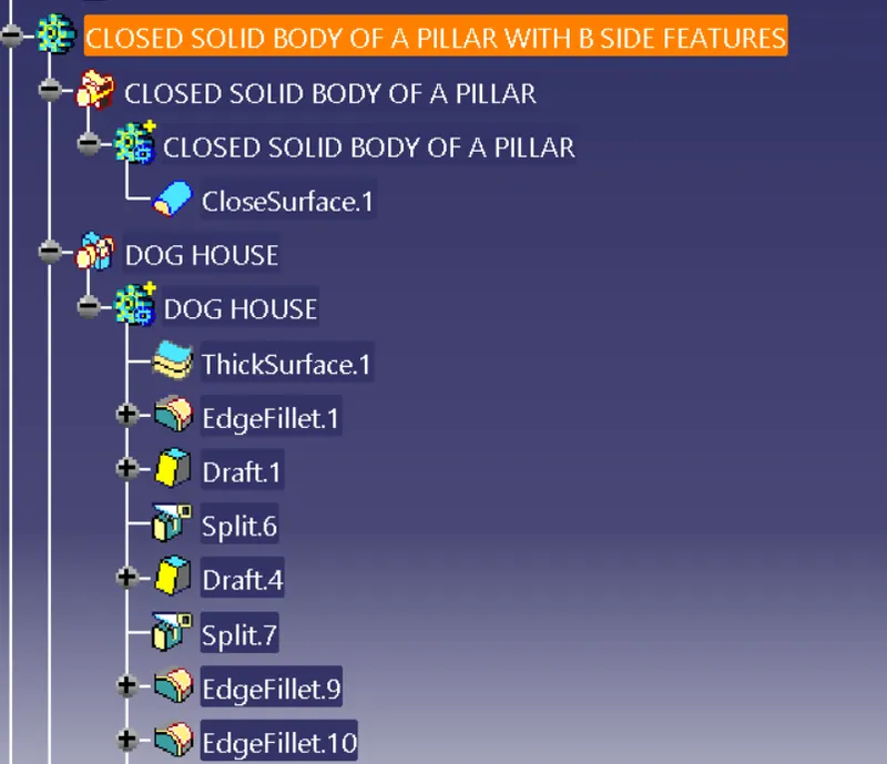
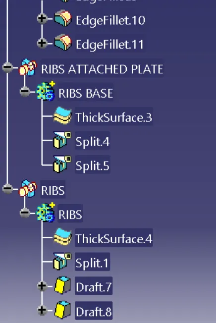
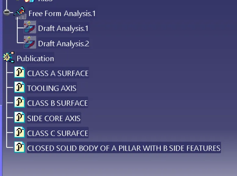
EXPANDED TREE FOR A PILLAR: