Week 9: Project 1 - Surface preparation and Boundary Flagging (PFI)
Aim: Simulate no hydro simulation for a Port Fuel Injection engine using converge and post process results using paraview.
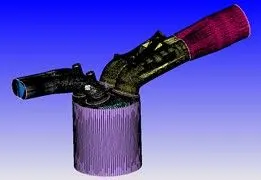
The geometry used in the simulation.
Setup-
Application Type-
Crank angle-based IC engine
Physical Parameters:
Bore =0.086 m
Stroke = 0.09 m
Connecting rod length = 0.18 m
RPM = 3000
Materials-
Gas Simulation- The therm.dat file was uploaded to import the thermodynamic properties of the fuel.
Reaction Mechanism – mech.dat file was imported for the simulation.
Simulation Parameters:
Run Parameters:
Transient, Crank angle based engine simulation, No hydrodynamic solver.
Simulation Time Parameters:
Start time : -480 deg
end time : 240 deg
initial time step/min time step: 1e-7/1e-8
max time step:0.0001
max convection/diffusion CFL limit: 1.0 / 2.0
Boundary Conditions:
Law of wall for velocity & temperature boundary conditions
- Piston-Velocity-piston motion, temperature - 450K
- Exhaust valve top – wall, translating, moving, temperature - 525K, Exhaust lift profile is imported
- Exhaust valve angle temperature - wall, translating, moving, temperature - 525K, Exhaust lift profile is imported
- Exhaust valve bottom - wall, translating, moving, temperature - 525K, Exhaust lift profile is imported
- Intake valve top - wall, translating, moving, temperature - 480K, intake lift profile is imported
- Intake valve angle - wall, translating, moving, temperature - 480K, intake lift profile is imported
- Intake valve bottom - wall, translating, moving, temperature - 480K, intake lift profile is imported
- Liner – wall, stationary, fixed, temperature - 450K
- Head - wall, stationary, fixed, temperature - 450K
- Spark Plug - wall, stationary, fixed, temperature - 550K
- Spark Plug terminal - wall, stationary, fixed, temperature - 600K
- Exhaust port - wall, stationary, fixed, temperature - 500K
- Intake port – 1 - wall, stationary, fixed, temperature 425K
- Intake port – 2 - wall, stationary, fixed, temperature 425K
- INFLOW - pressure - 1 bar total pressure, temperature - 363K, species - Air
- OUTFLOW- Pressure - 1 bar, temperature - 800k, species concentration – CO2(0.192304), H2O(.088559), N2(0.719137)
Regions and Initial conditions:
- Intake port - 1
IC8H18 - 0.025508
O2 - 0.20157
N2 - 0.77292
Temperature - 390k
pressure – 101325pa
- Intake port - 2
Air
Temperature - 370K
Pressure – 101325pa
- Cylinder region
Pressure – 101325k
Temperature - 300K
Species - CO2(0.192304), H2O(.088559), N2(0.719137)
- Exhaust region
Temperature – 1360K
Pressure – 185731pa
Species - CO2(0.192304), H2O(.088559), N2(0.719137)
Events
Cyclic
Cylinder region – intake port 1 – Valve
Cylinder region – exhaust region – Valve
Permanent
Intake port 1 – Intake port 2 - open
Turbulence Modelling:
RANS k-epsilon RNG model
Grid Control:
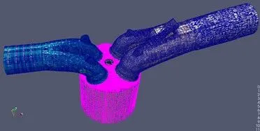
Base Mesh- dx=dy=dz=0.004m
Mesh
Graphs
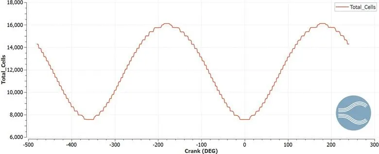
The total no of cells are shown in the graph above. It varies from 16000 to 7500 cells as the piston moves from TDC to BDC through the crank angle degrees.
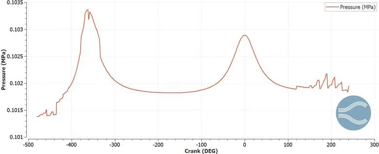
The pressure graph shows pressure variation across the crank angles. It can be seen it reaches 0.1034MPa pressure values however there are no reactions happening as this no hydro setup is just to check the mesh. Thus the values don’t provide a significant result of value.
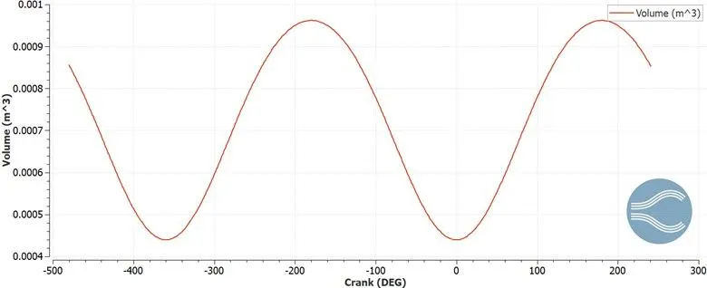
The volume graph shows variation of volume continuously through the crank angle degree or the piston movement in the chamber. It varies from 0.00044m3 to 0.00096 m3. However as the simulation is no hydro type to check the setup. There are no reactions happening and thus the significance is less.
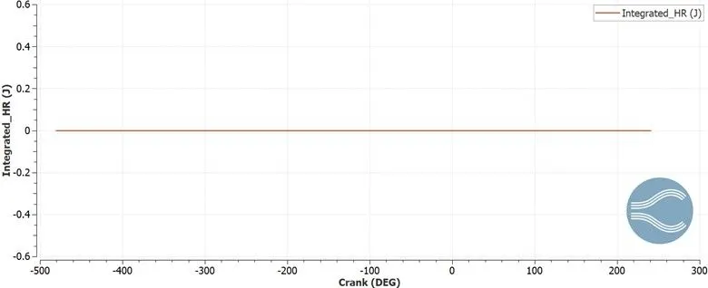
The Integrated heat release graph shows the heat release in Joules. The graph shows zero joules through the crank degree as the reactions are not happening and thus this no hydro simulation is checking the setup. As there are no reactions, the results are not of significance.
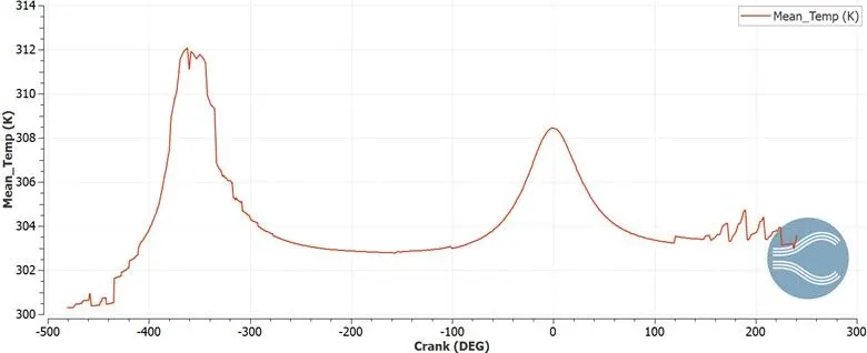
The mean temperature graph shows variation of temperature through the crank angle degree as the piston moves from TDC to BDC and vice versa. The max value is reached about 312K and as this is a No Hydro setup only to check if setup runs fine. There are no combustion or spray happening, the results are of minimal value.
Conclusion:
The No hydro setup for a PFI engine was simulated using converge.
As this no hydro setup was to check and simulate the setup without combustion, spray modeling, the pressure, temperature, Volume and heat release graphs are of minimal value.
The setup was run successfully without any errors.
Youtube Animation Link: