Week 9: Project 1 - Surface preparation and Boundary Flagging (PFI)
Aim- The aim of this project is to simulate the no hydro simulation for an ICE engine.
Theory:-An internal combustion engine (ICE) is a heat engine in which the combustion of a fuel occurs with an oxidizer (usually air) in a combustion chamber that is an integral part of the working fluid flow circuit. In an internal combustion engine, the expansion of the high-temperature and high-pressure gases produced by combustion applies direct force to some component of the engine. The force is applied typically to pistons, turbine blades, a rotor, or a nozzle. This force moves the component over a distance, transforming chemical energy into useful work.
Case Setup:-
1. The STL file consisting of the geometry was loaded into CONVERGE.
2. A diagnosis was run to evaluate the quality of the geometry. The following errors in the geometry were noticed
Intersections, Non-manifold Problems, Open Edges, Overlapping and Normal Orientation
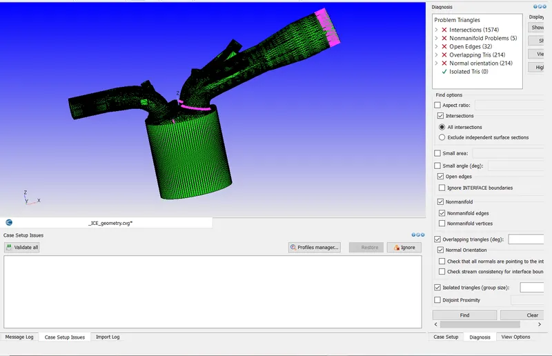
3. Prior to rectifying the errors in the geometry, Boundary's were first identified as follows.
- Piston:-
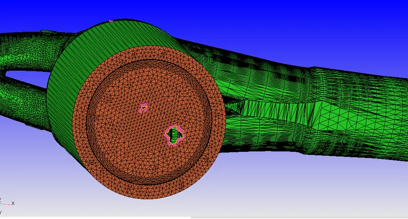
- Inlet (Light Yellow Highlighted)
- Liner (Yellow)
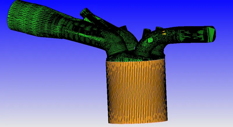
- Cylinder Head
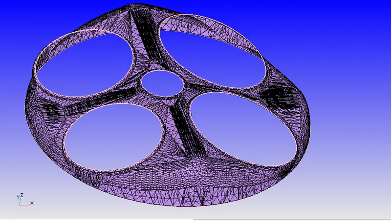
- Exhaust Port
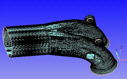
- Outflow

- Exhaust Valves
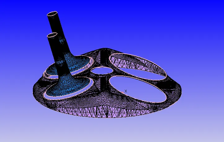
- Exhaust Valve Angle (Red Highlighted)
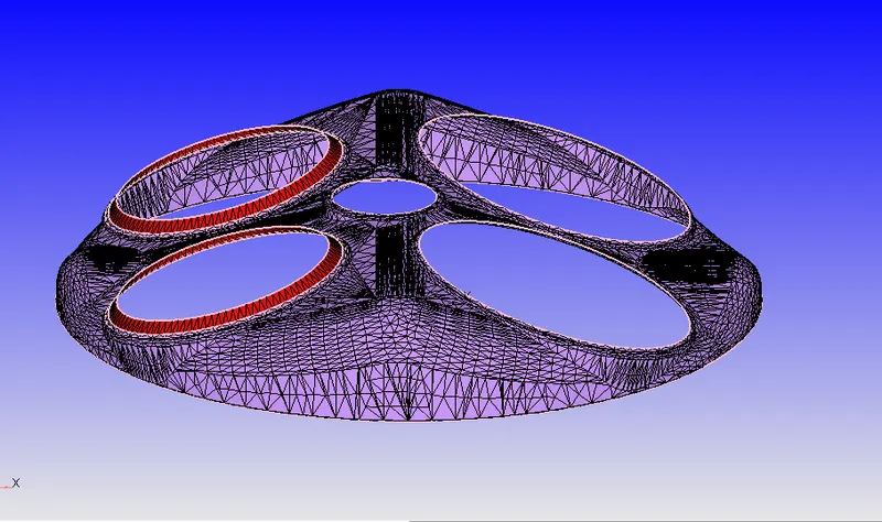
- Exhaust Valve Bottom (Green Colour)
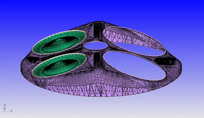
- Intake Port (Divided into two portions)
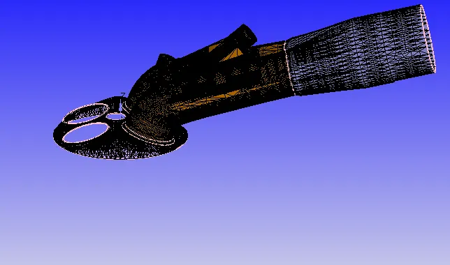
- Intake Bottom
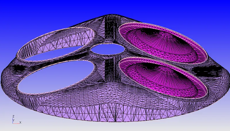
- Intake Angled (Light Yellow)
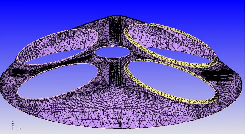
- Intake Valve
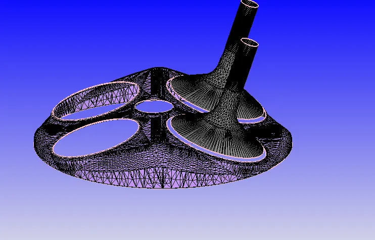
- Spark Plug Terminal
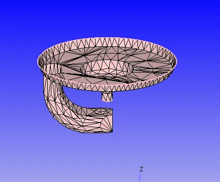
Rectification of Problems in Geometry
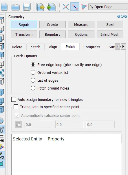
1. Open Loop Edges- The Geometry comprised of Open Edges in Piston, Exhaust Port and Liner. This was rectified using the following command
Geometry-Repair-Patch-Free Edge Loop- Edge Select- By Open Edge
- Piston before rectification
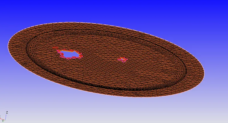
- Piston after rectification
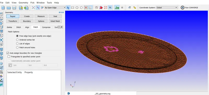
A similar procedure was adopted to rectify the other open edges
2) Intersecting Edges
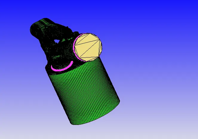
In the geometry, it was noted that the intake ports were interfering with the cylinder head. In the below snap, we can see that Intake port (green colour) clashing with cylinder head (purple).
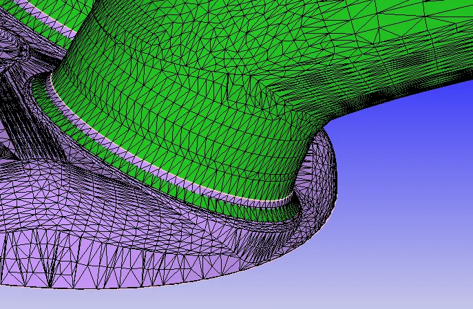
In order to rectify the above issue, The intake valve normal's were first computed. The normal vectors were noted. The intake valve was then translated by an amount of 0.005 to rectify this clash. The below command was used to rectify this problem
Geometry- Transform-Directional Vectors (Valve normal values inserted)- Translational amount.
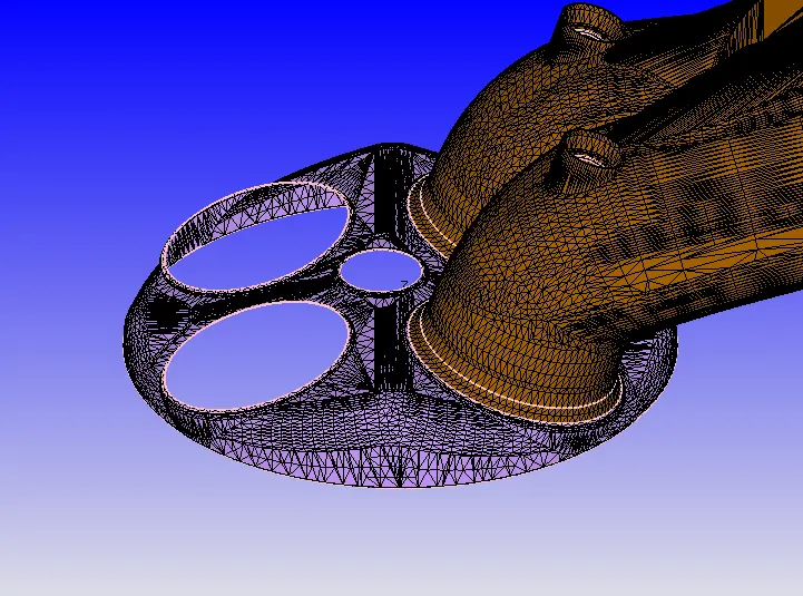
- Rectification of Normals- In the imported geometry all the normal vectors were pointing outwards. This was rectified by using the
Geometry-Transform-Normal-Propagate change from a single triangle.
This was done to ensure that the Normals pointed inwards in the direction of the flow.
Boundary Flagging
1. Application Type- Crank Angle based IC engine
2. Materials-
- Gas Simulation:- Defaults retained
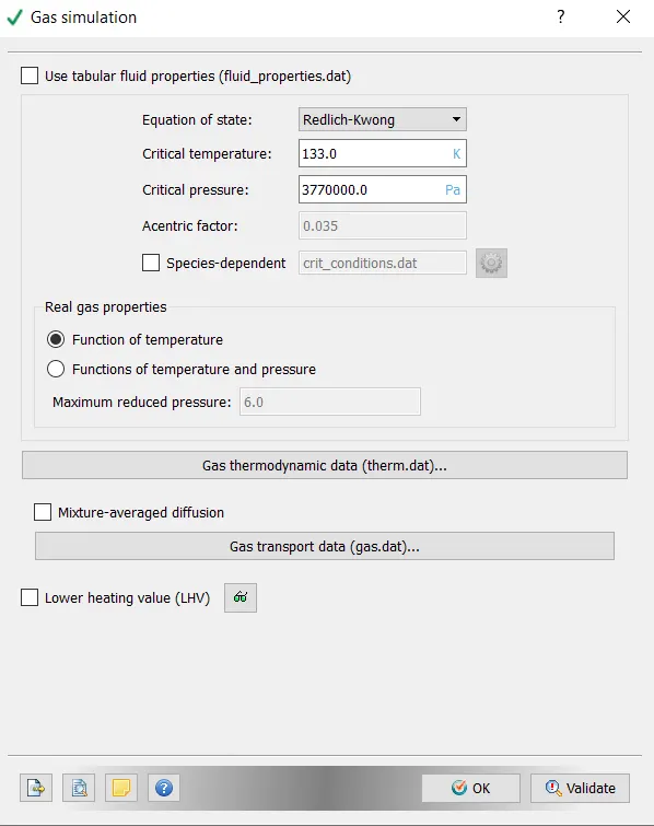
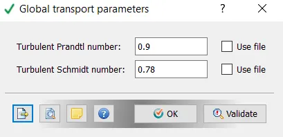
- Global Transport Parameters- Default retained
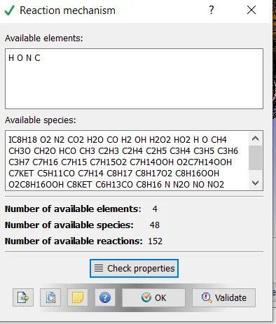
- Reaction Mechanism- For Reaction Mechanism, The mech.dat and therm.dat files provided were loaded into the simulation
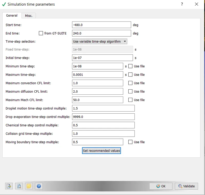
- Simulation Time Parameters:- Since the period of an ICE engine cycle is 720 degrees, the start and end time have been set keeping this in mind
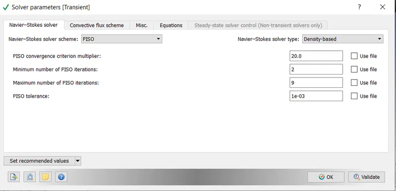
- Solver Parameters (Default has been retained).
- Regions and Initialization
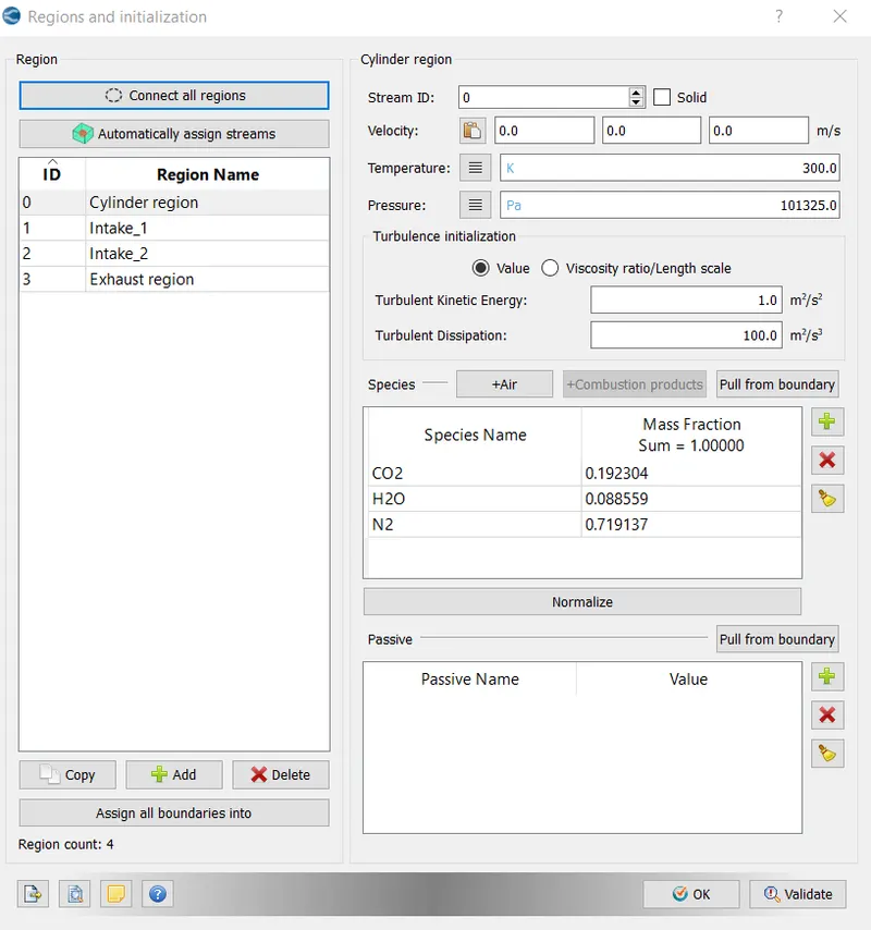
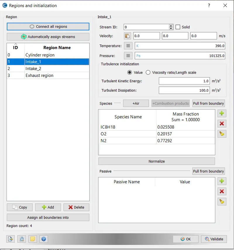
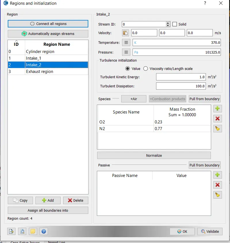
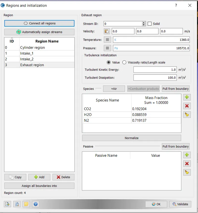
The ICE engines were classified into four regions, namely Cylinder, intake1, intake 2 and exhaust region
i) Cylinder Region:- The mass fractions of the species were calculated based on the requirement for complete/stoichiometric combustion
ii) Intake 1- The mass fraction for fuel air mixture were inserted based on typical composition for a standard ICE engine.
iii) Intake_2:- Since air is taken in from intake port 2, the typical composition of air has been inserted.
iv) Exhaust Region:- Since whatever gas is to be exhausted through the exhaust region, comes from the combustion chamber, the composition of the exhaust gases are same as that of the cylinder region.
Events
- To synchronize the cyclic opening of the intake and exhaust ports, events were created. The timing of the opening were obtained theough the exhaust.in and intake.in files
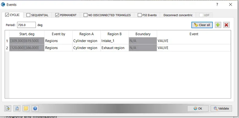
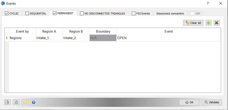
Also the intake valves would be open throughout the combustion cycle. So a Permanent event was created.
- Permanent
Boundary Conditions
The component of the ICE engine was classified into different region as shown below
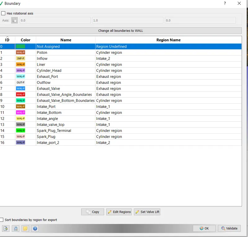
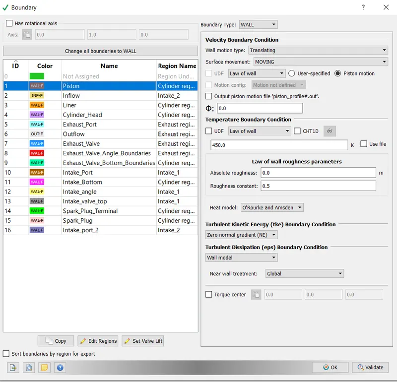
The boundary condition for each of the component has been set as shown below.
- Piston:- Boundary Type- Wall
- Inflow:- Boundary Type- Inflow
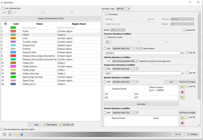
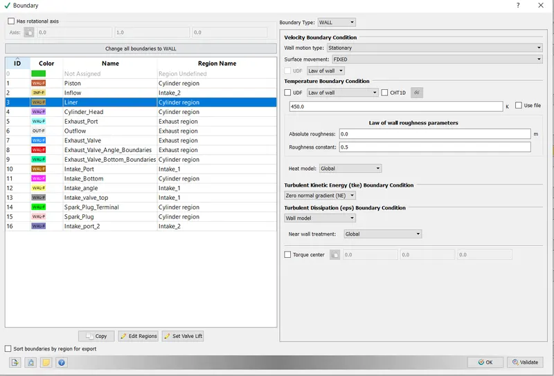
- Liner:- Boundary Type- Wall
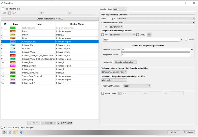
- Cylinder Head:- Boundary Type- Wall
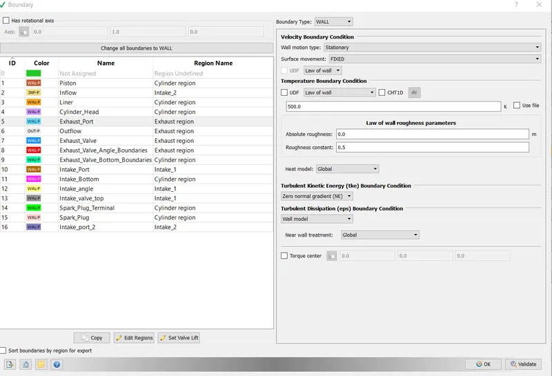
- Exhaust Port:- Boundary Type- Wall
- Outflow:- Boundary Type- Outflow
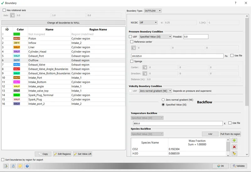
- Exhaust Valve:- Boundary Type- Wall, Movement as per exhaust_lift.in
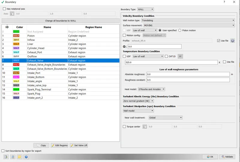
- Exhaust Valve Boundaries:- Boundary Type- Wall. Movement as per exhaust_lift.in
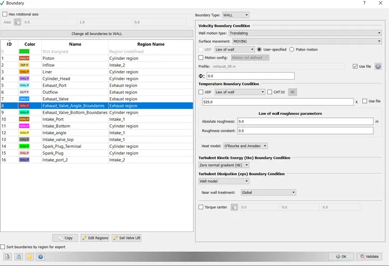
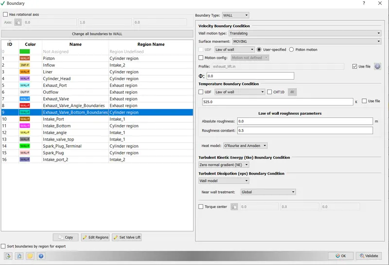
- Exhaust Valve Bottom Boundaries:- Boundary Type- Wall. Movement as per exhaust_lift.in
- Intake Port:- Boundary Type- Wall
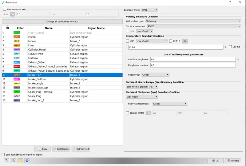
- Intake Bottom:- Boundary Type- Wall. Movement as per intake_lift.in
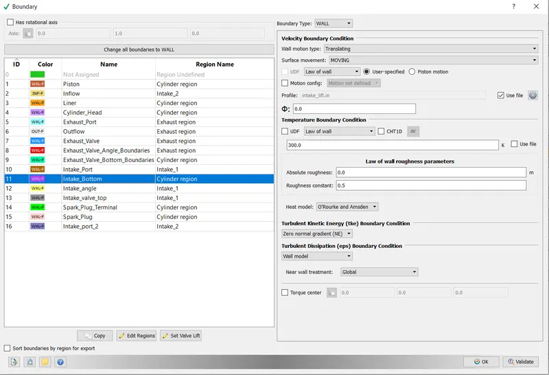
- Intake Angle:- Boundary Type- Wall. Movement as per intake_lift.in
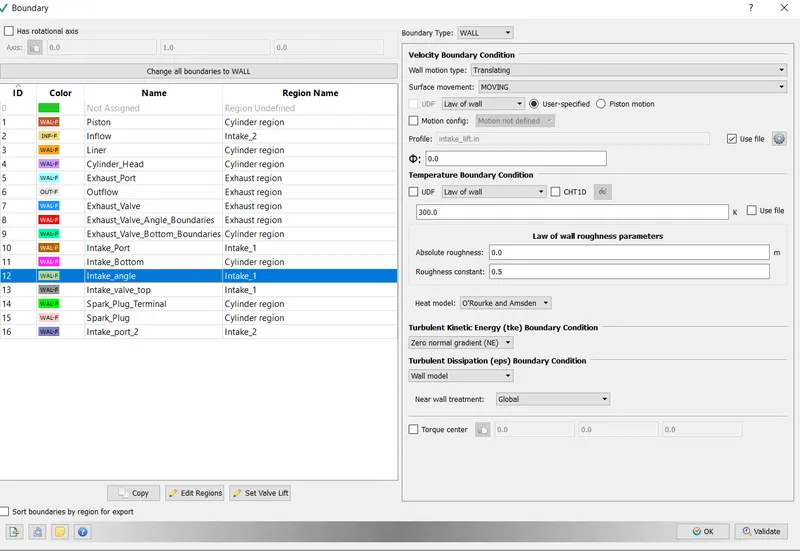
- Intake Valve Top:- Boundary Type- Wall
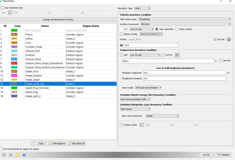
- Spark Plug Terminal :- Boundary Type- Wall
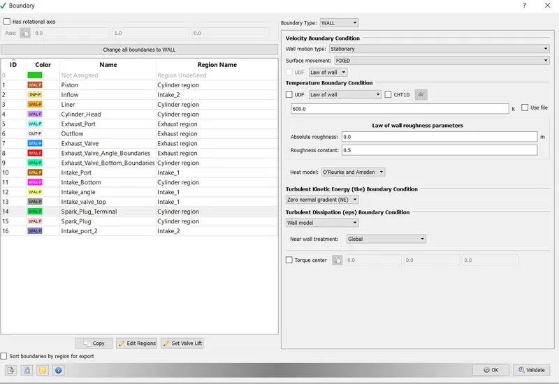
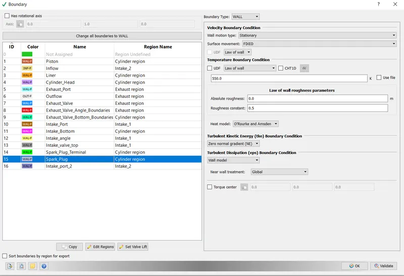
- Spark Plug:- Boundary Type- Wall
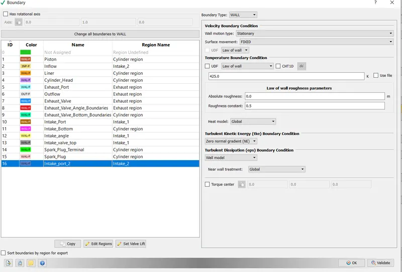
- Intake Port:- Boundary Type- Wall
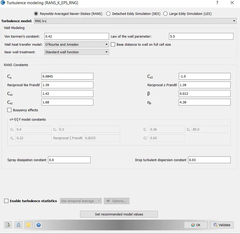
- Turbulent Modelling:- RNG k-epsilon model is used.
- Base Grid:- An element size of 0.005 m has been selected,
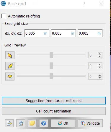
-Fixed Embedding was enabled. This was done to ensure local refinement of the mesh so as to better capture the flow properties. Converge uses an octri data structure.
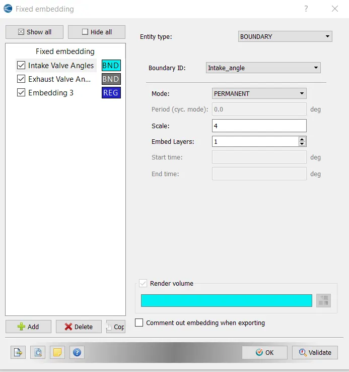
a) Intake Valves: Embedding type Boundary, mode of embedding- Permanent. Scale factor is 4. This means the mesh cell size value at intake is 0.005/4=0.00125
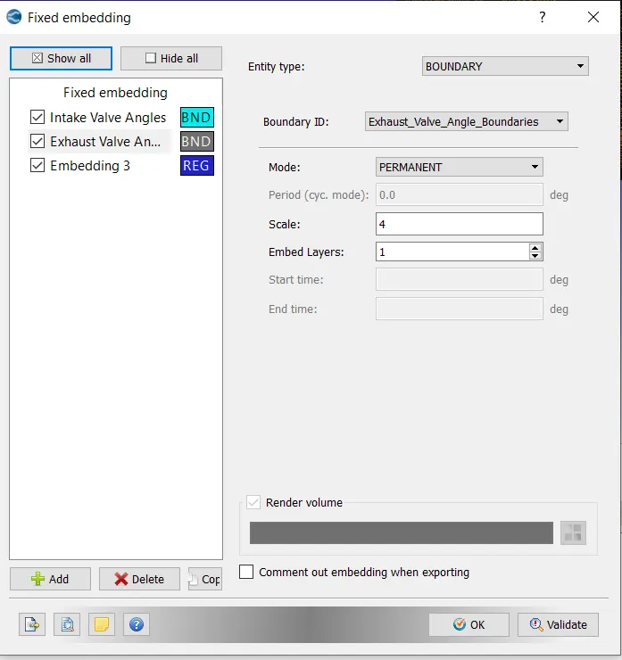
b) Exhaust Valve= Embedding type Boundary, mode of embedding- Permanent. Scale factor is 4. This means the mesh cell size value at intake is 0.005/4=0.00125
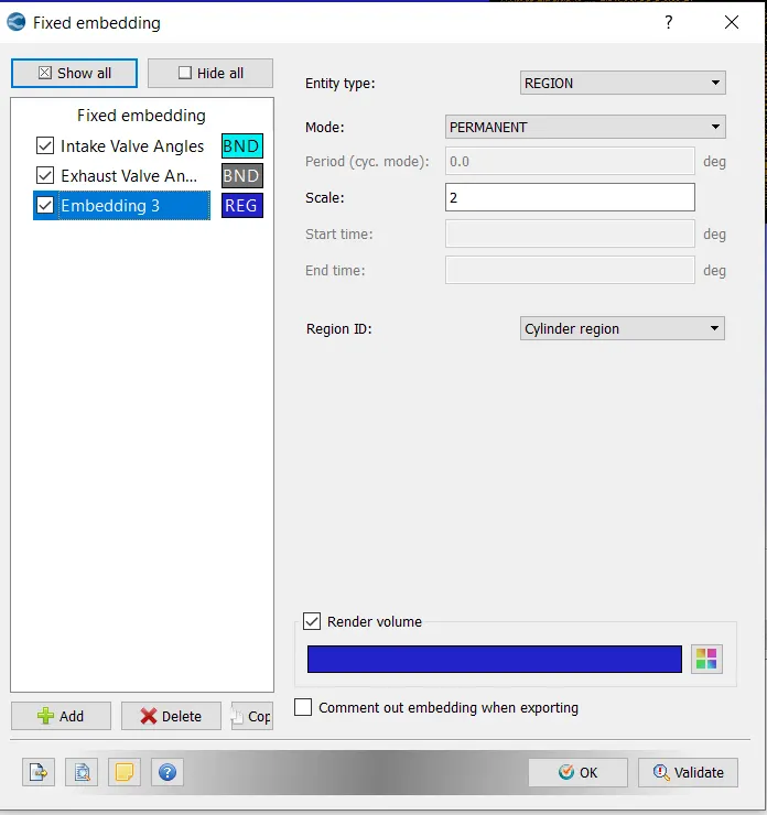
c) Cylinder region:-Embedding type Boundary, mode of embedding- Permanent. Scale factor is 4. This means the mesh cell size value at intake is 0.005/2=0.0025
After setting the above, the input files were exported to a directory.In order to execute the simulation, the directory in which these input files were stored was accessed in Cygwin and the following command was typed "mpiexec.exe -n 4 converge.exe"
After the Simulation was executed, the results were converted into a form which would be compatible with Paraview. This was done using the post_convert.exe command.
Results
i) Mesh Generation
https://drive.google.com/file/d/1Hg6g26P_pDj2AnVHWU3lJTbWMTG5JW9y/view?usp=sharing
ii)Valve Movement
https://drive.google.com/file/d/1cLgqUvIdkgfbtQa0j2X7Q45e9vMM2kZv/view?usp=sharing
Conclusion
In this project, the no hydrodynamic model was set up and observed in converge. THe Valve motion and mesh refinement were found in accordance with the expected result.