Week 9 - Project 1 - Door Trim Lower with Engineering Features
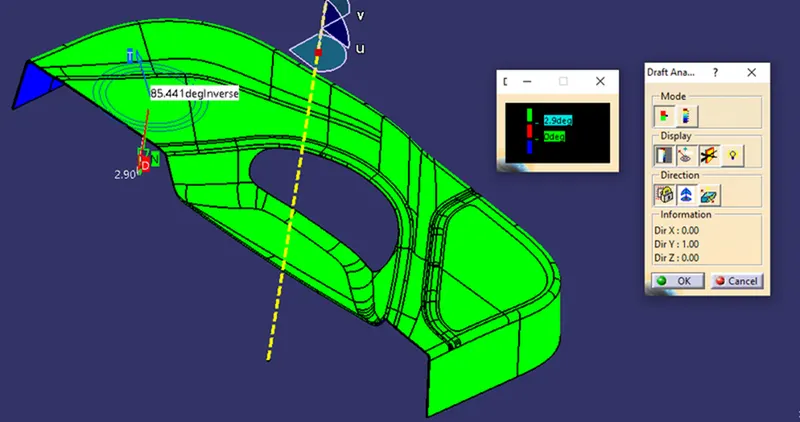
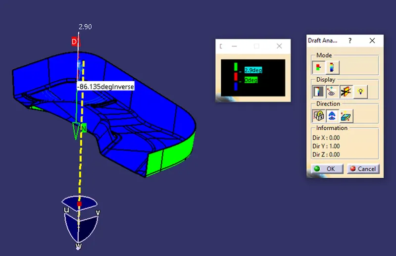
AIM:- TO Create the DOOR TRIM component through the given Class-A surface and the tooling axis for the given Class-A Surface should be created meeting the requirements of the draft angle and at the end perform the Draft analysis on the model.
PROCEDURE:-
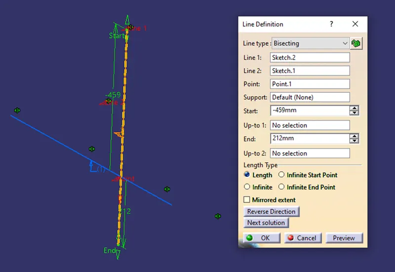
First i created the maion tooling axis from the class A surface by creating the plane and intersect the surface a with the plane and created the sketch and bisect the two lines and created the main tooling axis.
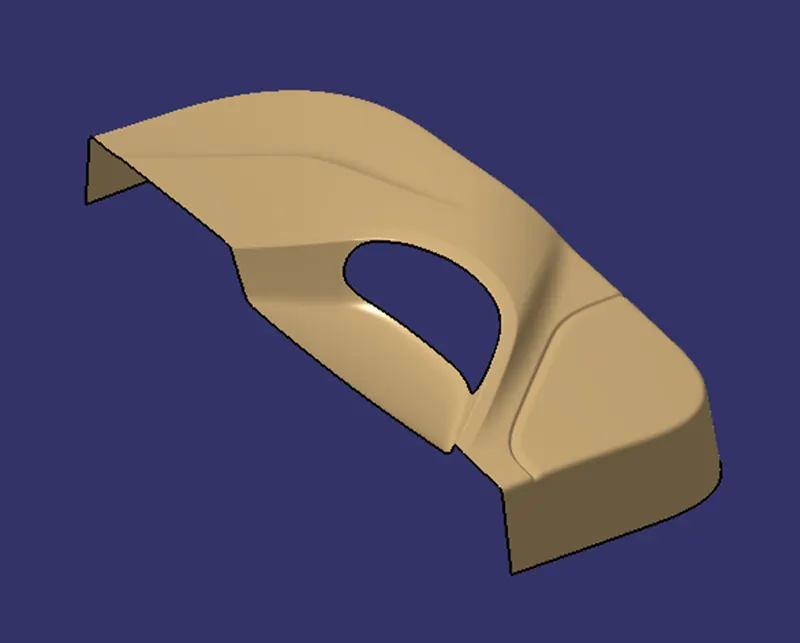
CLASS A SURFACE:-
MAIN TOOLING AXIS:-
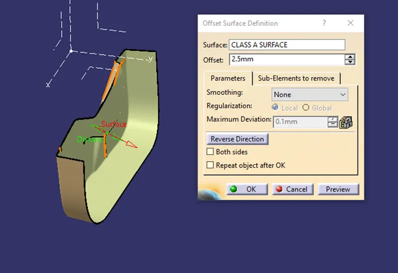
creating the class B surface by offseting the class A and clear all the patches that are left after the offset as shown below
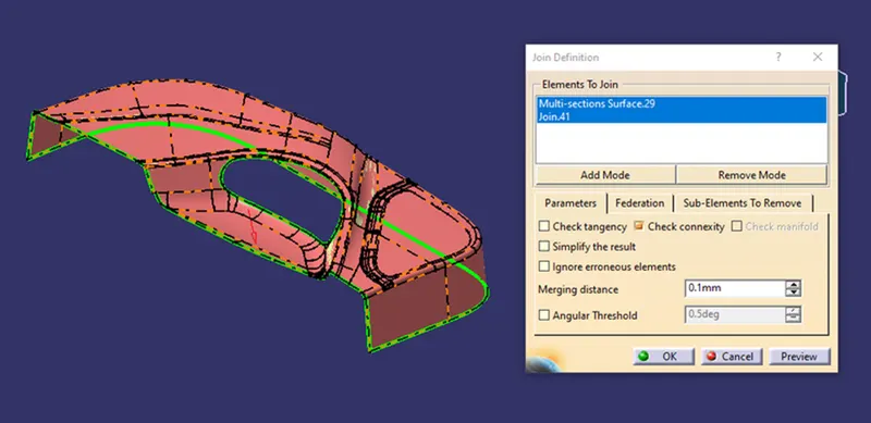
and finally create the class B as shown below
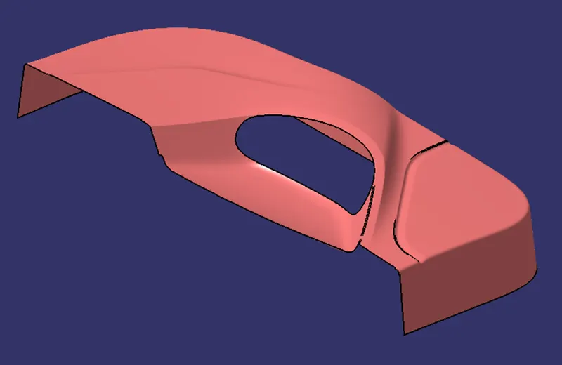
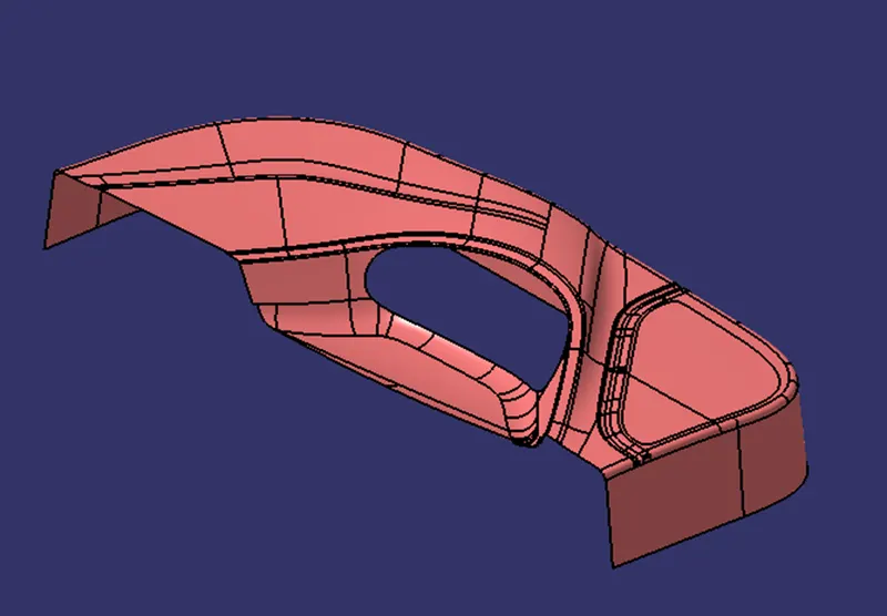
then create the class C by taking the boundary from the class A and sweep with the reference surface and created the class C as shown below
By using the tool multiextrapolate and sweep with the reference surface of class A created the small and small sweep and final join all the sweep and join with the class A and created the class A and class C as shown below
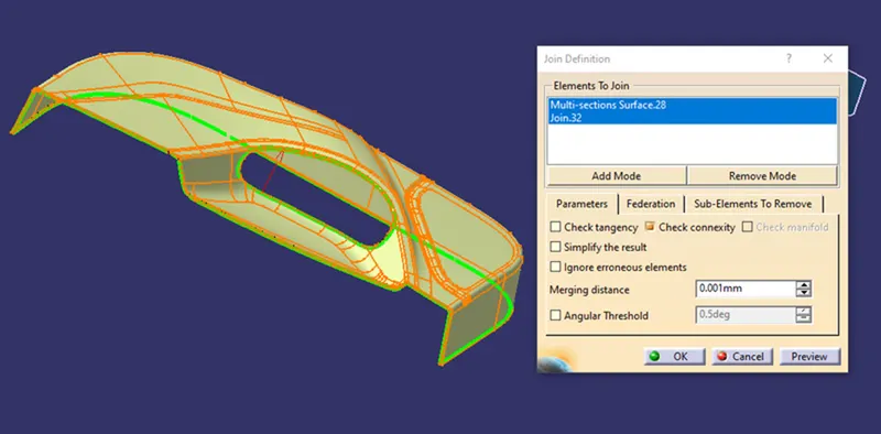
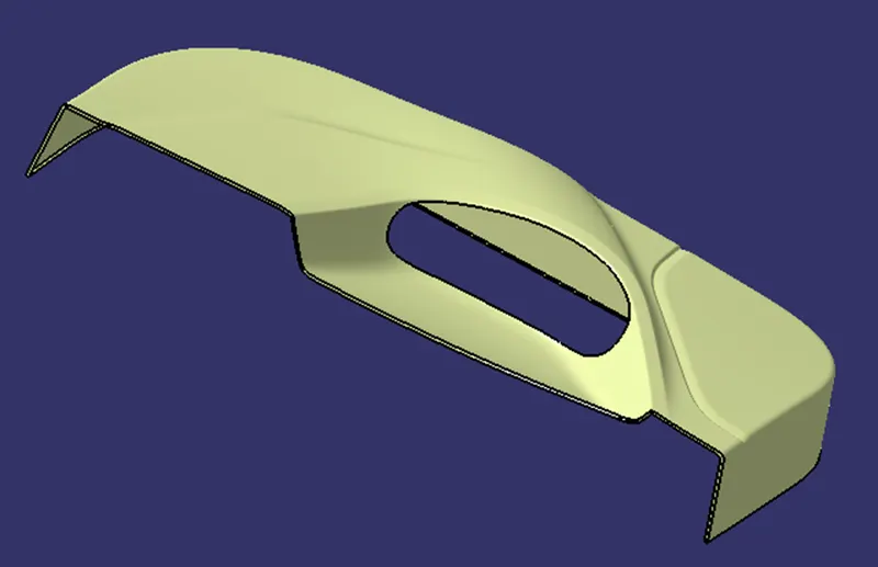
and then trim both the join A and c with the class B as shown below
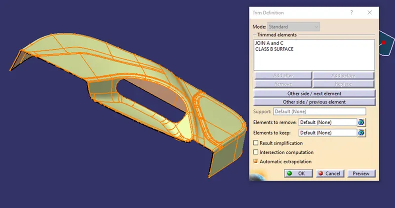
first i checked the intersection between the join and the class B
FINAL TRIM
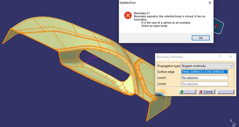
Checked the close boundary and checked in the part design for the close surface and finally created the close surface door trim as shown below
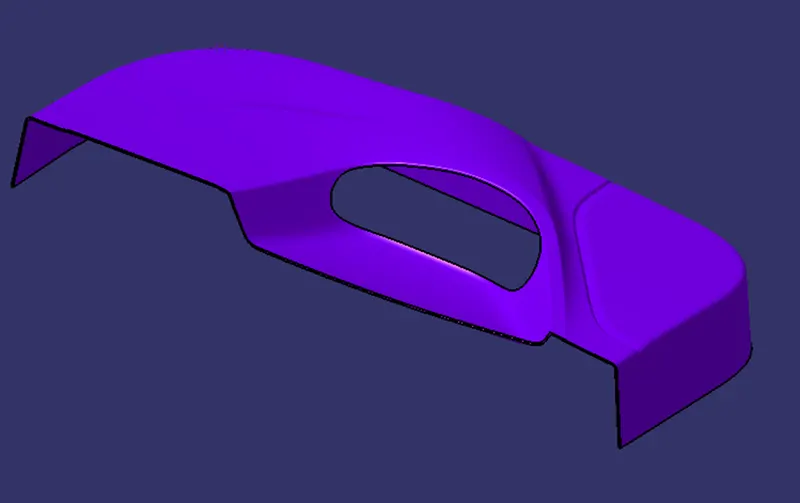
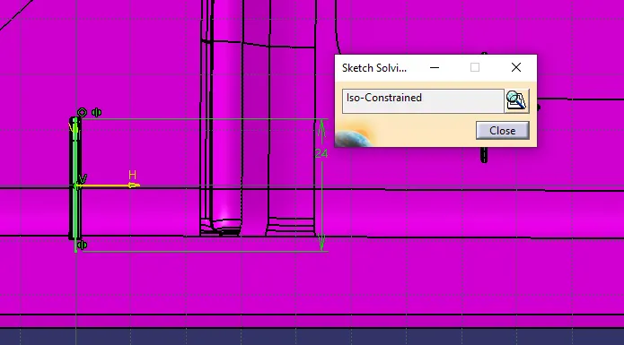
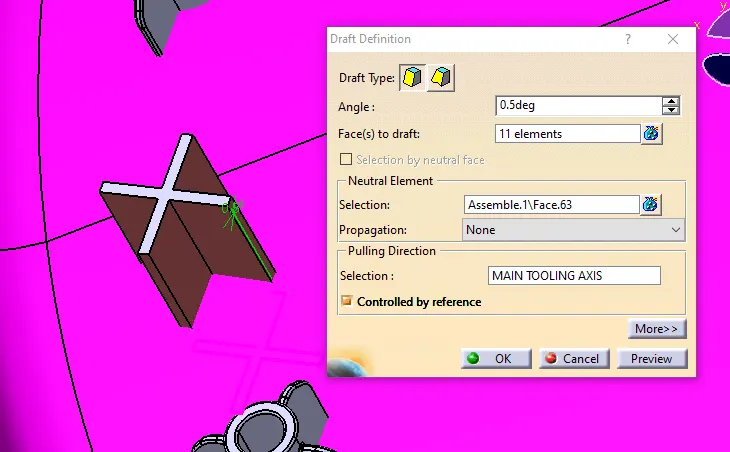
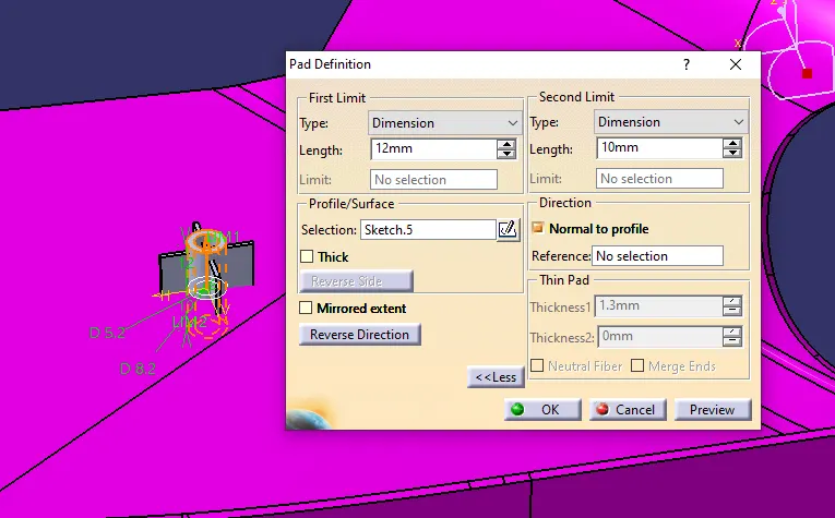
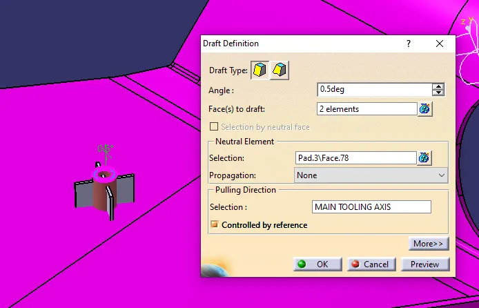
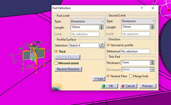
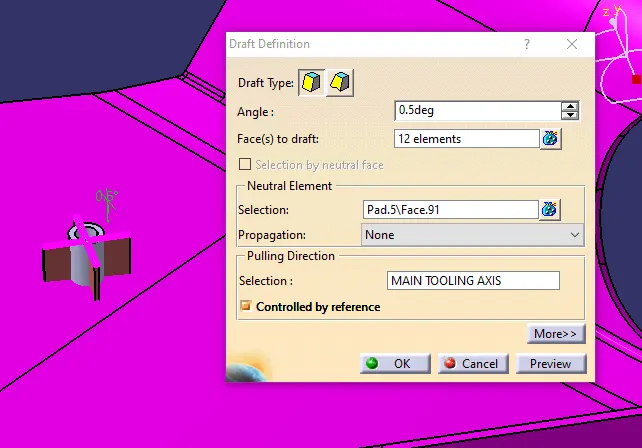
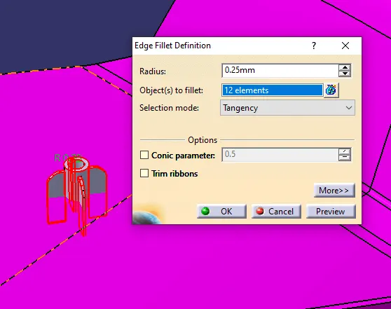
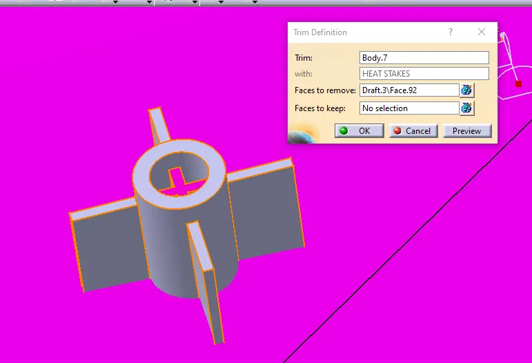
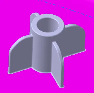
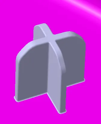
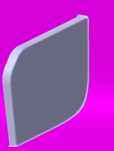
Then i created a new geometrical set with a name 4 way locator and 2 way locator and created a sketch and created the new body and construct the 4 way and 2 way and provided the draft of 0.5 and fillet and union trim with the main body and all this done by taking the extract surface from the class b surface and created the point and after ffinal 4 way and 2 way locator i union trim with the main body as shown below
4 way locator
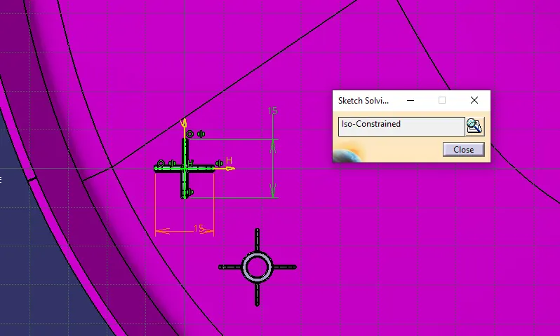
2 way locator
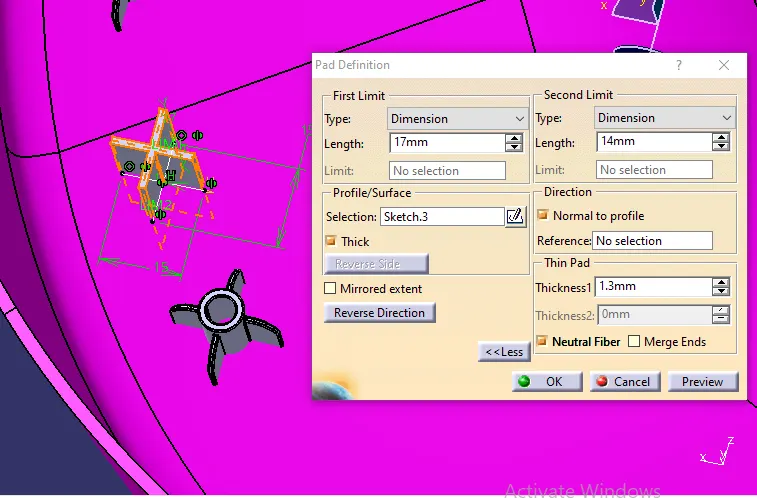
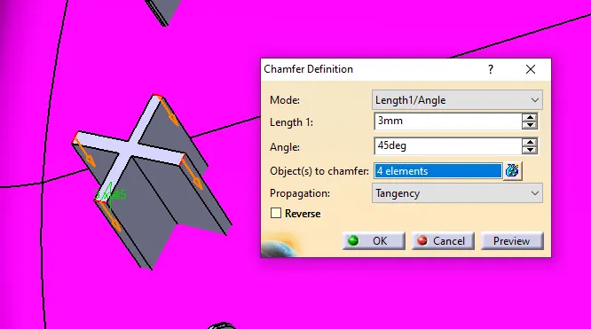
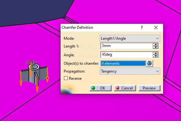
4 way locator pad feature and chamfer of 3mm in 45 degree and fillet provided as shown below
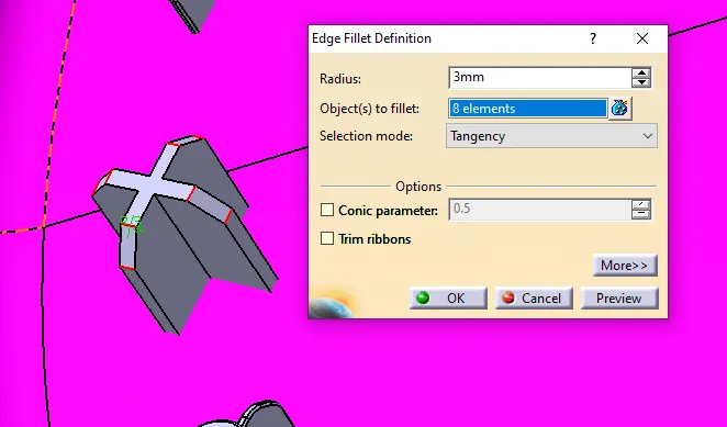
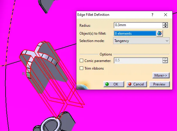
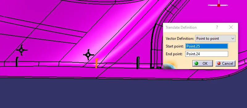
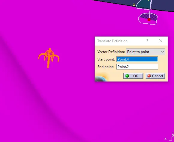
Then use the translate locate the 4 way locator from point to point as per the required challenge as shown below
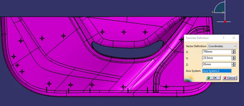
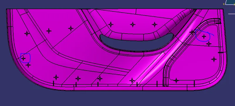
2 way locator pad feature, draft it and chamfer of 3mm in 45 degree and fillet provided as shown below
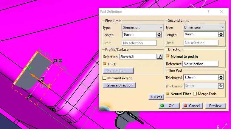
4 way locator pad feature and chamfer of 3mm in 45 degree and fillet provided as shown below
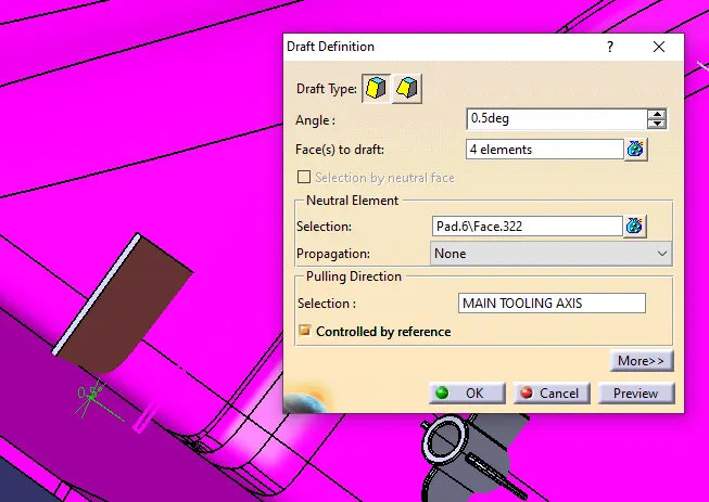
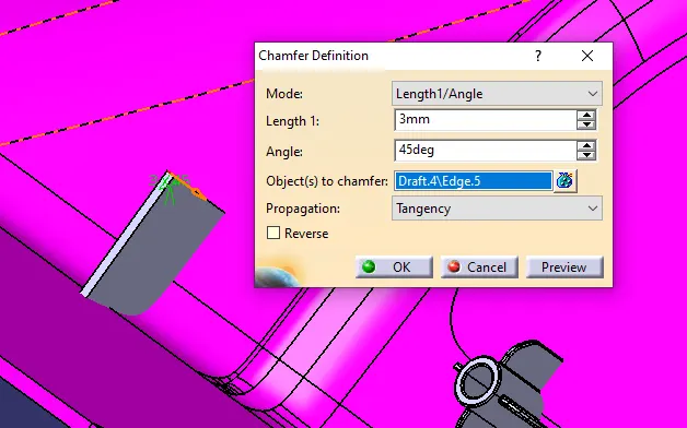
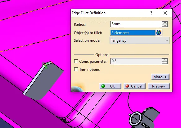
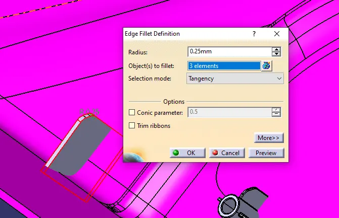
Then i created the point according to the challenge for the 2 way locator and translate the 2 way locator as per the challenge as shown below
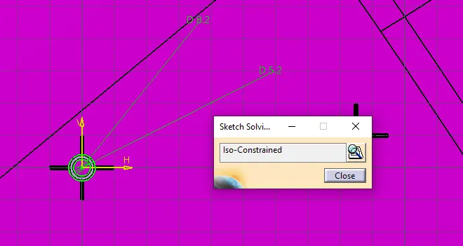
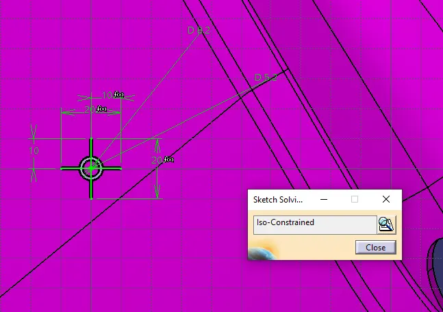
Then i created the heat stake by extracting the surface and created the point as a cordinated and adjust it with respect to the challenge and created the sketch and pad it draft it and chamfer and fillet it and translate all it in one body with the copy paste from the main foldet with a link and union trim that all heat stake in body into the main body as shown below
PUBLICATION:-
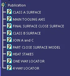
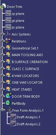
GEOMETRICAL TREE OF DOOR TRIM WITH THE HEAT STAKE AND THE LOCATOR:-
DRAFT ANALYSIS OF CLASS A
DRAFT ANALYSIS OF CLOSE SURFACE OF CLASS A B AND C

DRAFT ANALYSIS OF THE HEAT STAKE AND THE LOCATORS
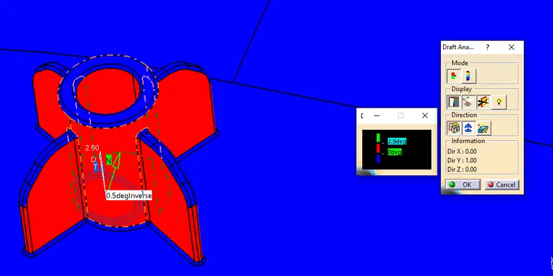
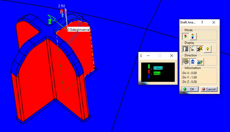
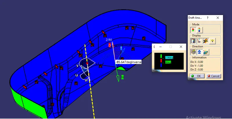
INVERSE THE DRAFT DIRECTION AS SHOWN BELOW
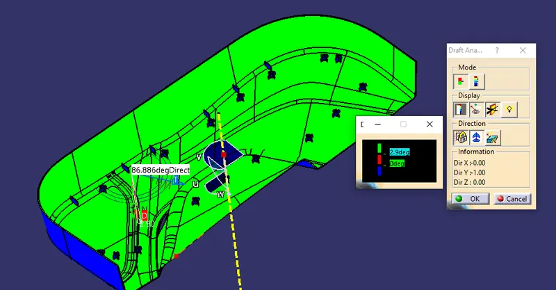
ORIENTATION VIEW
ISOMETRIC VIEW
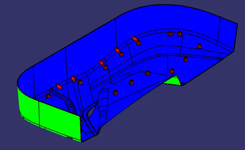
FRONT VIEW:-
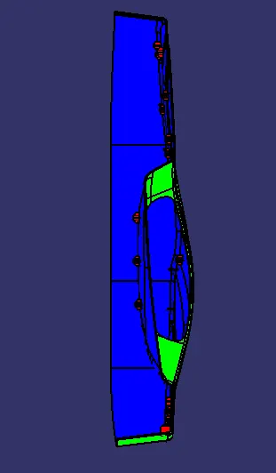
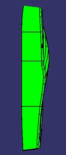
SIDE VIEW:-
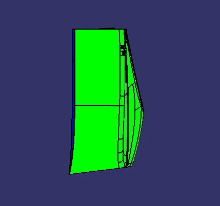
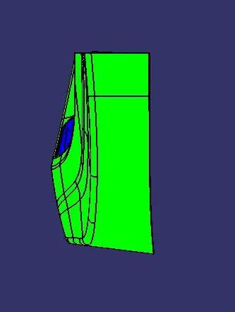
TOP VIEW
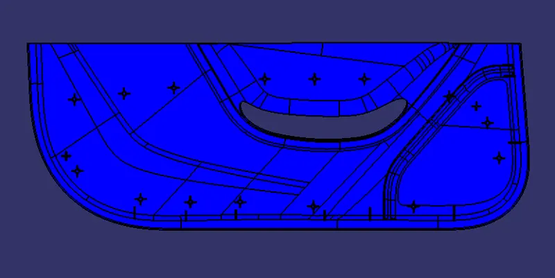
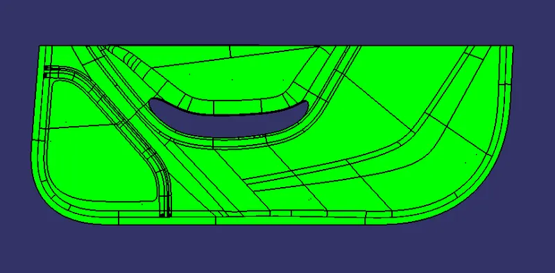
FINALLY THE AS PER THE CHALLENGE OF HEAT STAKES AND THE LOCATOR AS PER THE LOCATION SHOWN BELOW
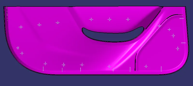
CONCLUSION:-
Finally created the class B and class C from the class A and created the close surface model of the DOOR TRIM and also created the 4 way and 2 way locator and the heat stakes as per the challenge and done the draft analysis and gave the orientation view.