Week 8 - Challenge 1 - Base Bracket Design
OBJECTIVE:-
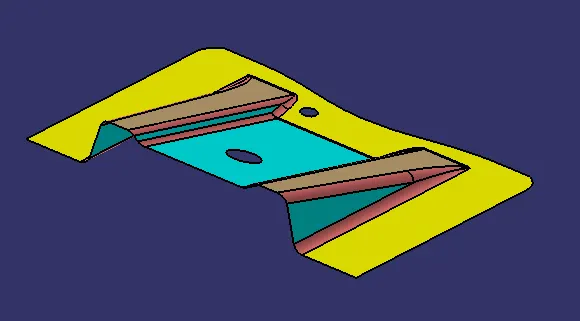
To design the base bracket by using the class A surface using the catia v5
INTRODUCTION:-
By using the class A surface we are going to create a solid part by following OEM regulation. The designed part should be ready for molding so, the part is designed by assigning the proper draft.
PROCEDURE:-
- Import the class A surface and check the patches on the surfaces.
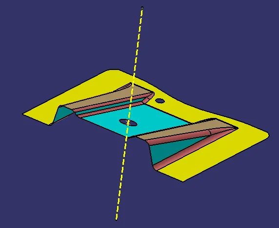
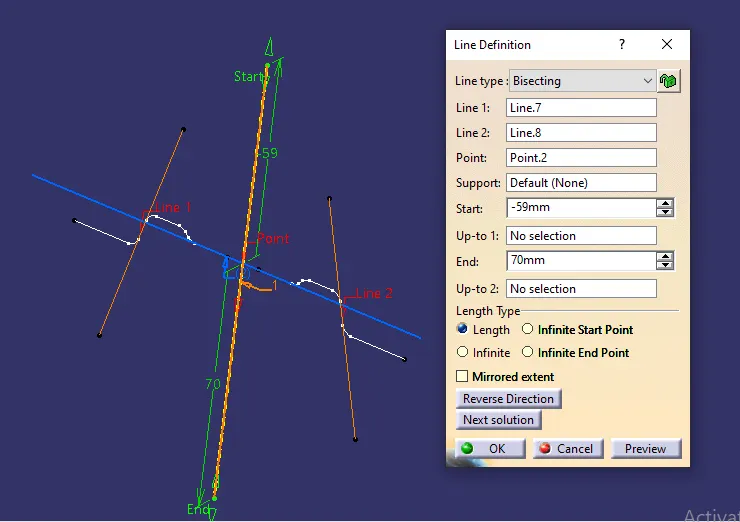
- Add the point at an appropriate location and create a new axis system ot the point location and then create the axis and create the intersection and lines on the draft side and bisect bothe the lines with the axis and create the tooling axis.
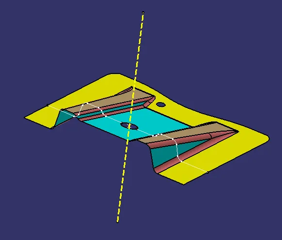
Then to create the B surface we started extracting the ribs 1 and ribs 2 drom the class A surface and extraplolate the surface and trim the surface as per the class A and created the following surface of B surface
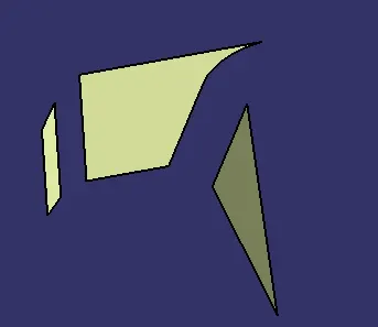
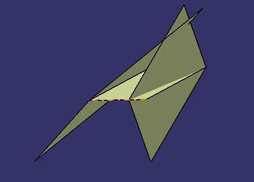
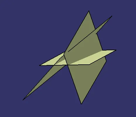
Then after trimming i created a offset of 2.5 mm downward direction and same process done to ribs 2
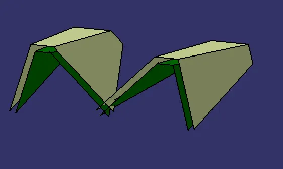
Then after that i extract the surface from the class A as a BASE SURFACE and extraplote and untrim the surface and after that trim the extraplote surface according to the class A aurface and offset the surface to 2.5 mm as shown below
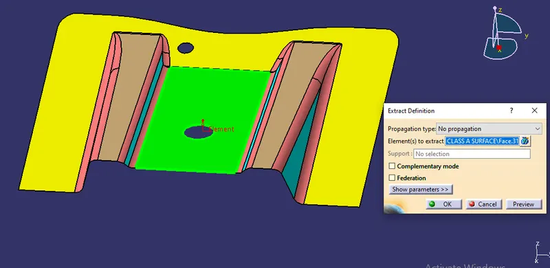
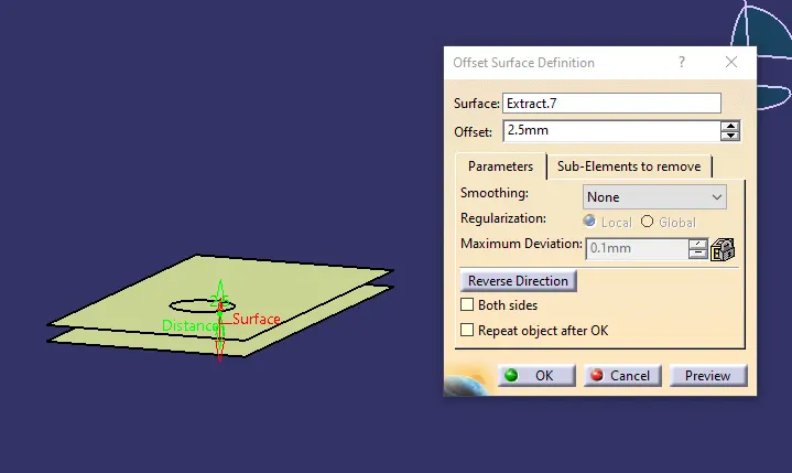
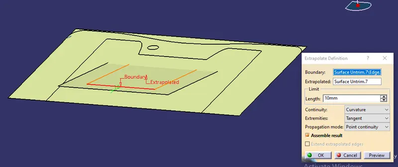
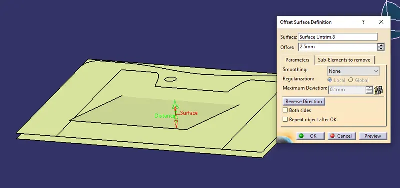
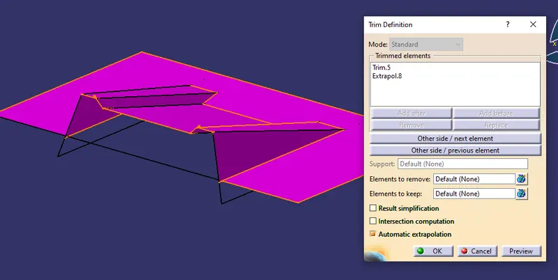
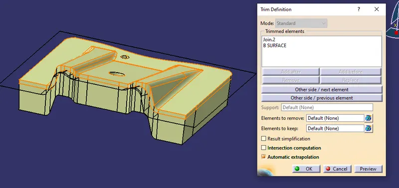
Then i created a final trim to the base surface of the complex surface by taking the reference of surface A and created the following B surface as shown below
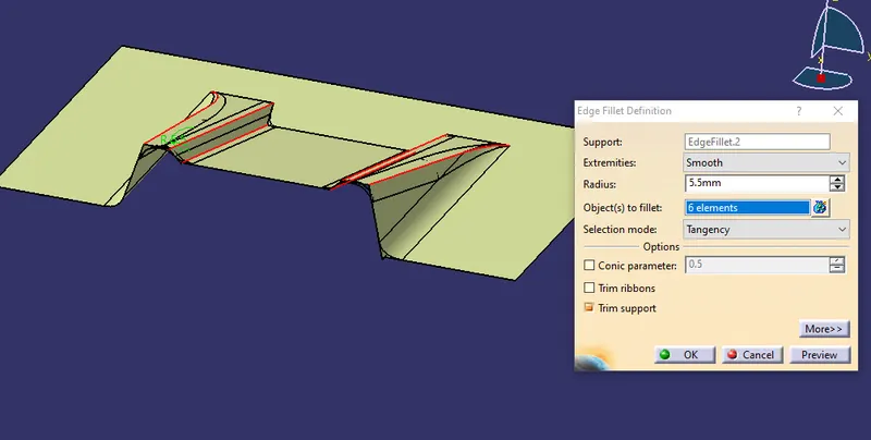
Then i applied the fillet to the class B surface by 3mm+2.5 mm value as it has offest of 2.5 mm and
by observing from the class A surface it looks to be 3mm fillet by calculating its fillet value will be 5.5 mm as shown below
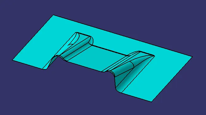
And finally CLASS B surface obtained as shown below
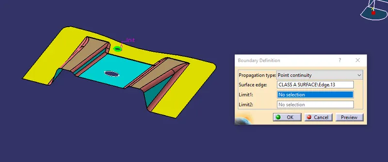
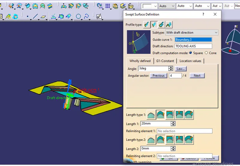
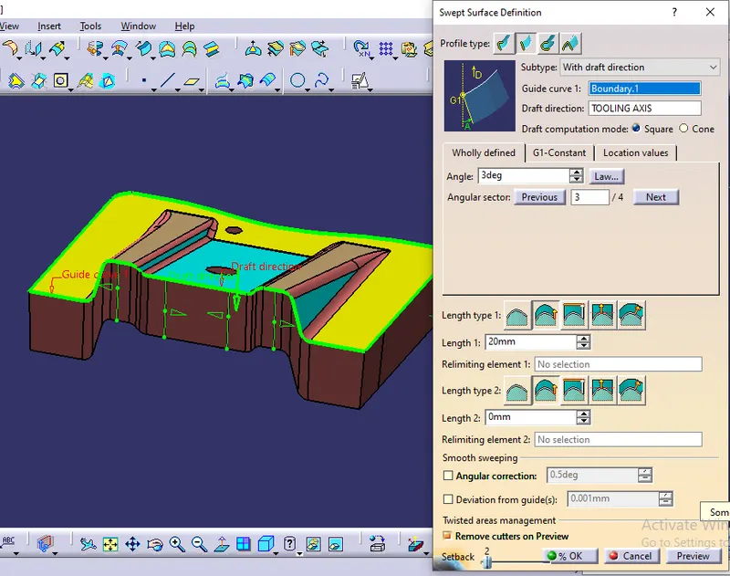
Then i created the surface c by creating the boundary from the class A surface and also created the 2 nos hole from the class A surface and with the help of the tooling axis and draft direction under sweep command i created the CLASS C surface as shown below
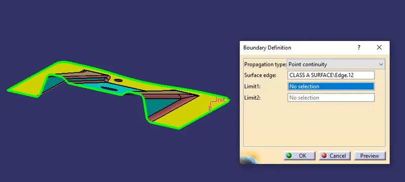
Then join both class A and class C and trim with the class B as shown below
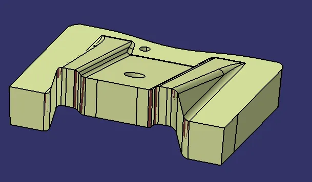
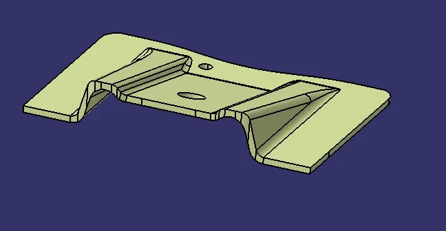
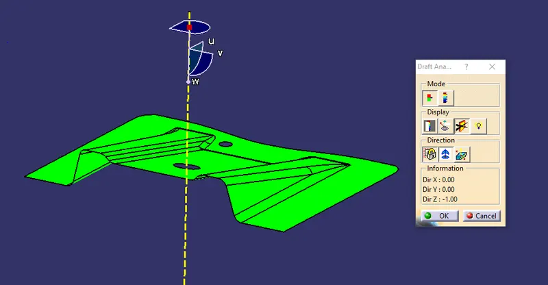
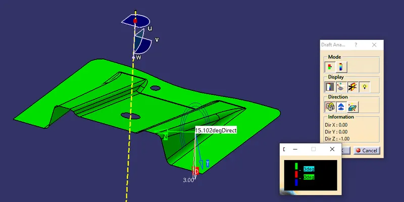
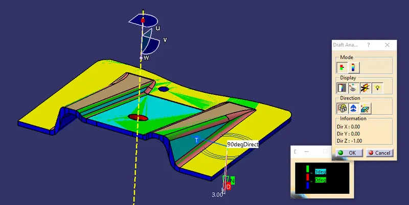
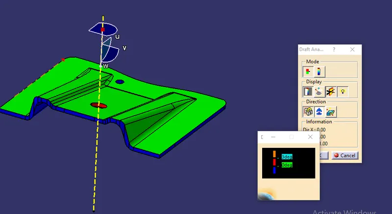
Drafting analysis of the base bracket
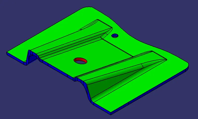
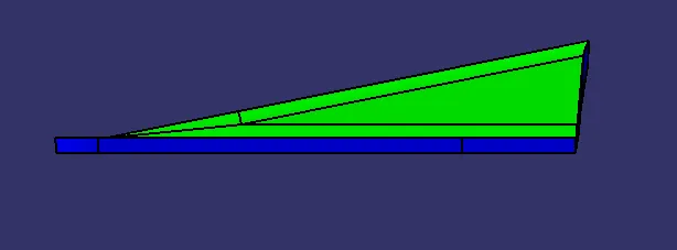
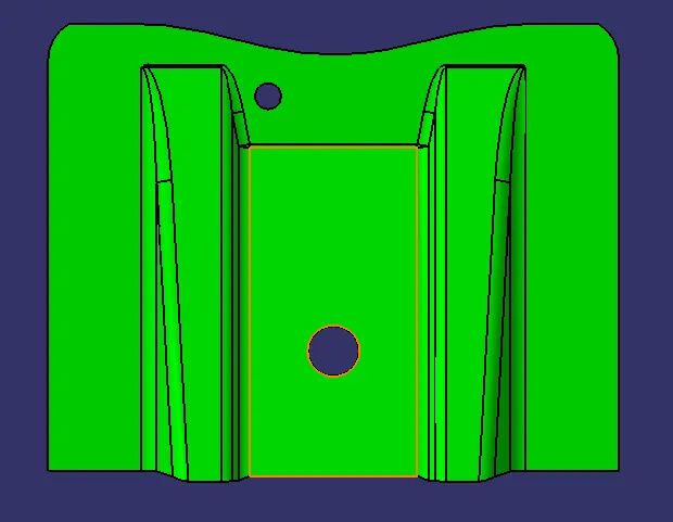
The various orientation of the solid model as shown below
ISOMETRIC VIEW:-
FRONT VIEW:-
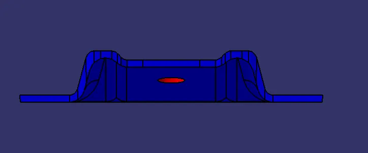
SIDE VIEW :-
TOP VIEW:-
CONCLUSION:-
In this project designed the base bracket and made ready for manufacturing by allowing a proper draft according to the requirement.