Week 9 - Project_1 - Door Trim Lower with Engineering Features
NOTE: I have Attached the Report, Photos and CADpart in the Attachment
Week 9 - Project_1 - Door Trim Lower with Engineering Features
AIM:
To Create the Door Trim Lower Plastic component through the given Class-A surface. To begin with, the tooling axis for the given Class-A Surface should be created meeting the requirements of the draft angle and at the end perform the Draft analysis on the model.
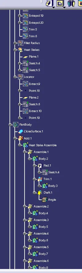
To Create the Heat Stakes and the locators considering the design rules mentioned in the video for the door applique.
OBJECTIVE:
- Sketches
- Use Positioned sketch
- Sketches should be Iso-Constrained
- References
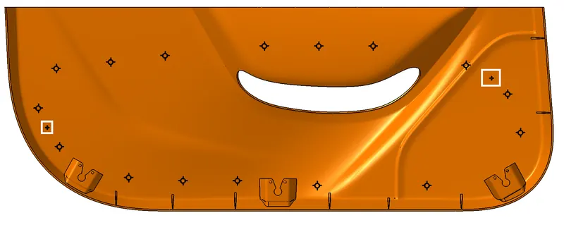
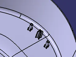
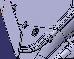
- Use the given points in the model to create the locators and Heat stakes
- Refer to the below-given image for more details
- Tree Structure
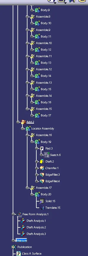
- Ensure Proper Tree Structure
- Geometrical sets should have a proper name based on the sketches present inside of it
- All the sketches should be created under the Geometrical set
- Report
- A detailed report should be done explaining the draft analysis and the tooling axis creation.
- An explanation should be given on the way of creating the tooling axis, particularly the Bisecting method.
SOFTWARE USED : CATIA
Let us look at how we have designed
INPUT:
CAD DATA is downloaded and Opened with CATIA.
TOOLING AXIS:
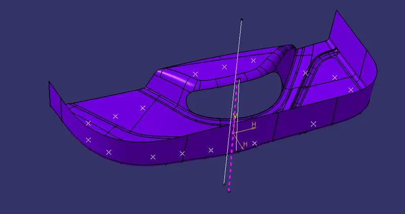
Tooling axis is defined as such all the features of the part can be manufactured easily. so here we followed the below steps to create the tooling axis.
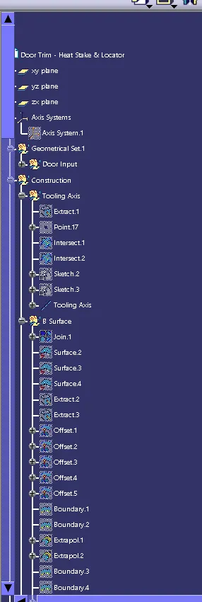
- Extract the base and Create a point in the middle of the surface.
- Create a axis on the point
- Intersection is taken with the axis system and Class A.
- Sketch is drawn with taking the intersection curve and draw a line with bisecting.
- Another line is drawn with a sketch
- Both the lines are taken for bisecting and getting the Tooling Axis
- Hence we get the Tooling Axis
DRAFT ANALYSIS:
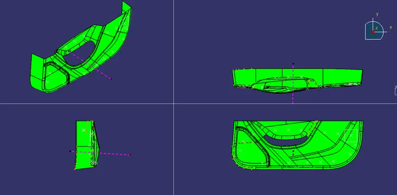
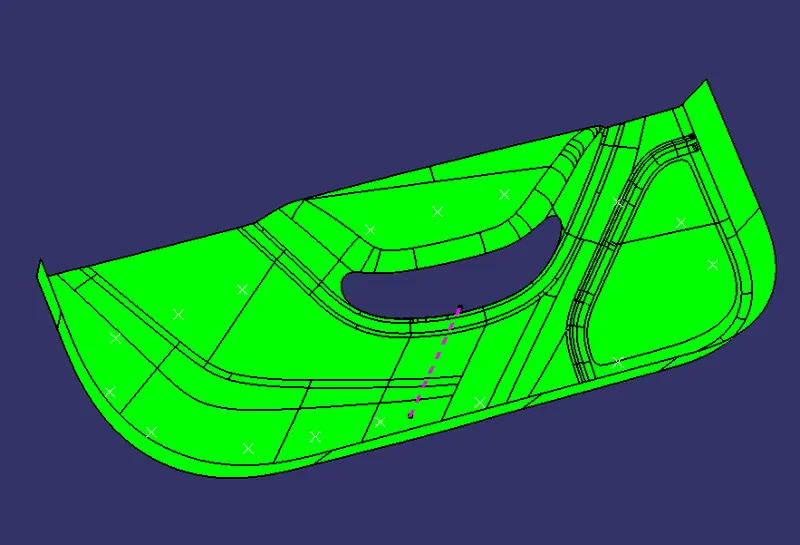
- Draft is done on the Class A surface.
- Change it to material in customise view.
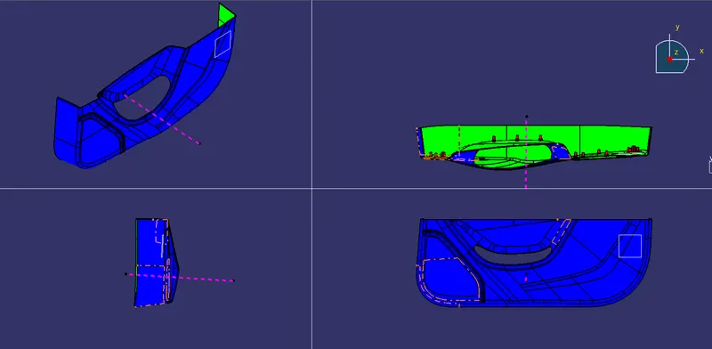
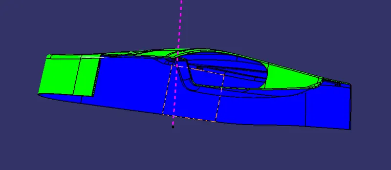
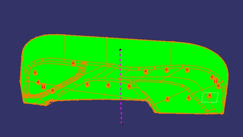
- Click the Draft analysis tool and click the surface and align the compass to tooling axis.
- 3 degree is the clearing angle
- So here is photo of cleared (Green) draft.
B SURFACE:
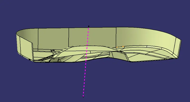
- B surface is created by using the given Class A surface.
- Apart complicated face join other faces.
- Offset it to 2.5mm beneath the Class A.
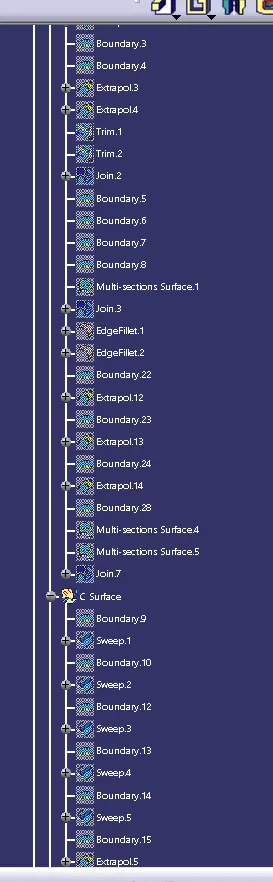
- Create boundry and Create MSS, Extrapolate for the rest of the sections.
- Trim the extrapolates and join if needed.
- Hence we have created the B surface.
C SURFACE:
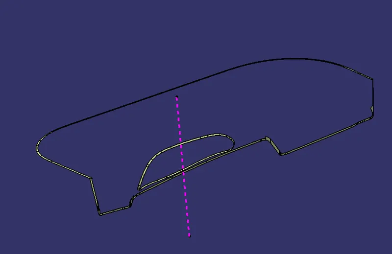
- The outer edge of the Class A surface is taken as reference boundry.
- Sweep is made with reference to tooling axis with draft.
- Join the sections and create the C Surface.
FINAL TRIM:
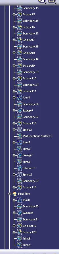
- Join A and C surface.
- Trim with the B surface.
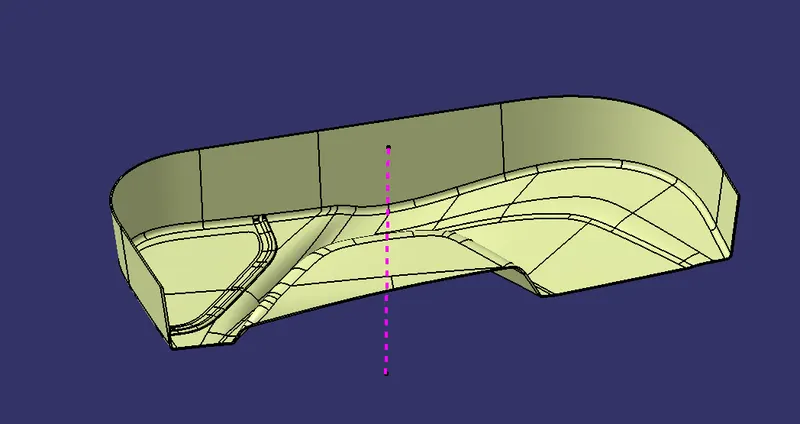
- Closed Body is created
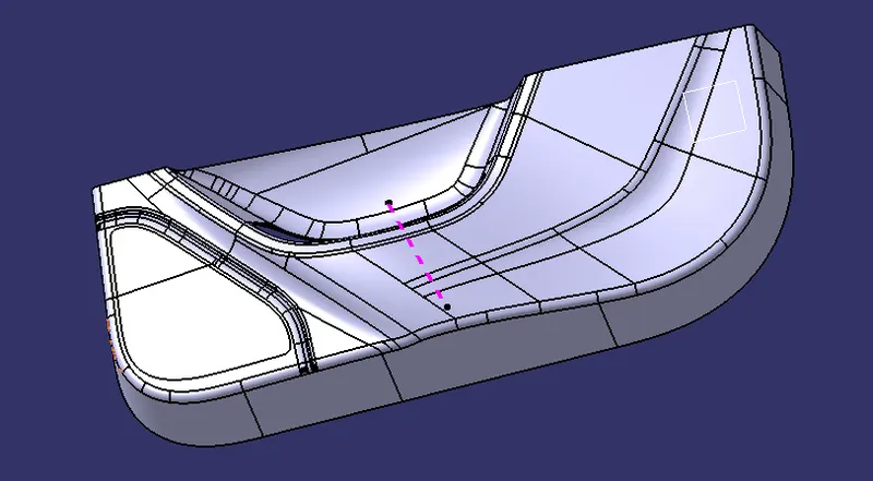
Heat Stakes:
- Heat stakes are created on the mentioned points
- Sketch is drawn with nominal diameter and ribs are also drawn.
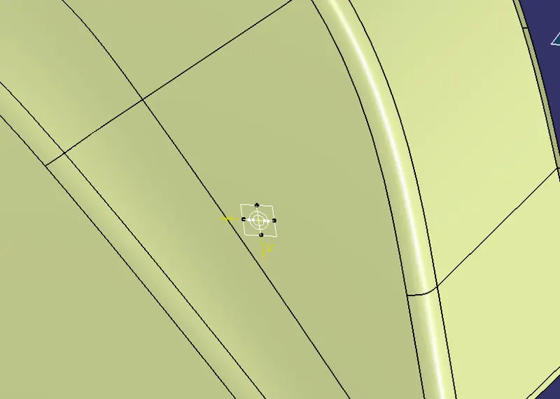
- Switch to part design and pad the sketches and given draft along the tooling direction
- Translate this body to all the points
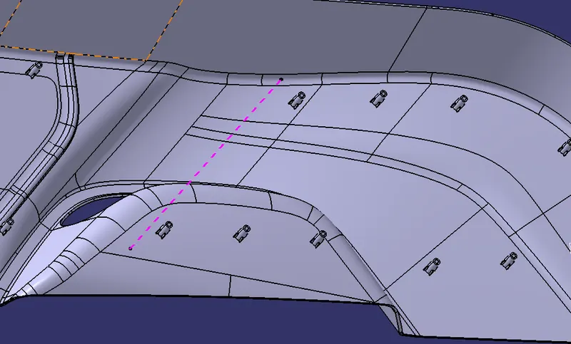
Locators:
- Locators are also added at specified positions as per the question
- Sketch is drawn and it is padded in part design
- Draft is given to the feature.
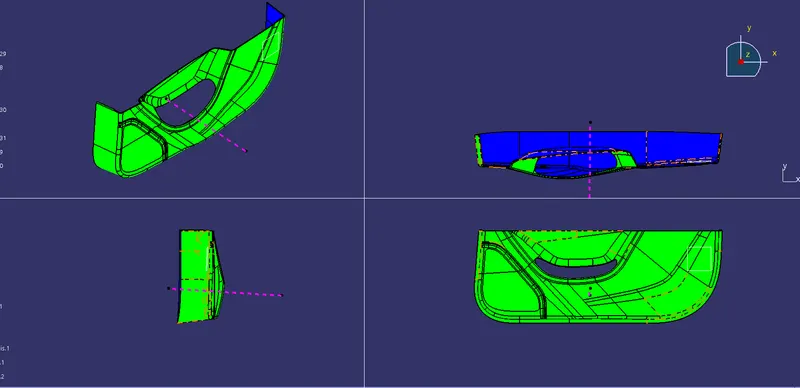
DRAFT ANALYSIS:
- Draft is done on the Class A surface.
- Change it to material in customise view.
- Click the Draft analysis tool and click the surface and align the compass to tooling axis.
- 3 degree is the clearing angle
- So here is photo of cleared (Green) draft.
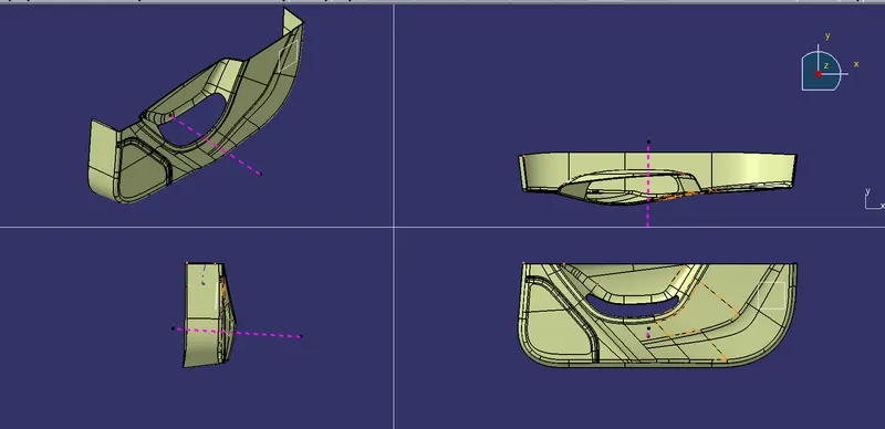
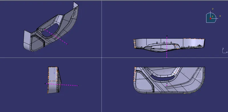
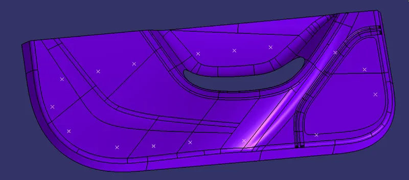
Here are few photos of the model