Week 9 - Project_1 - Door Trim Lower with Engineering Features
DOOR TRIM LOWER WITH ENGINEERING FEATURES
AIM:
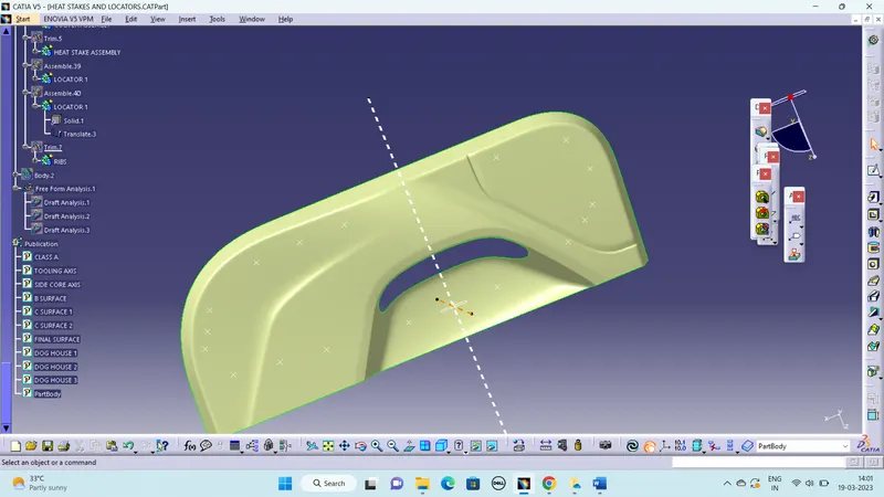
Create the Door Trim Lower Plastic component through the given Class-A surface. To begin with, the tooling axis for the given Class-A Surface should be created meeting the requirements of the draft angle and at the end perform the Draft analysis on the model. Create the Heat Stakes and the locators considering the design rules.
GIVEN DESIGN:
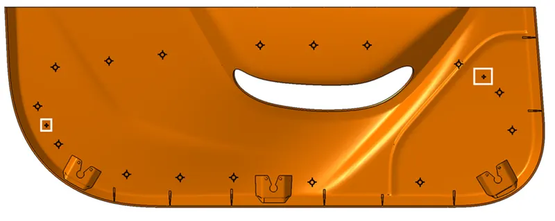
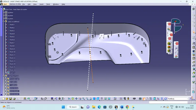
CLASS A SURFACE:
Class A is an aesthetic surface with the highest quality finish. Most Class A Surfaces for an Automotive Component are made using AUTODESK ALIAS. It is taken as a reference by the Automotive Plastic Designer to create CLASS B, CLASS C surfaces.
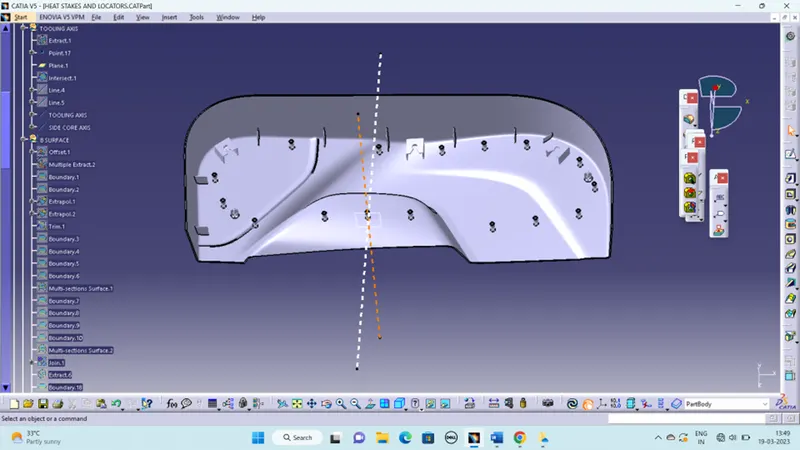
TOOLING AXIS:
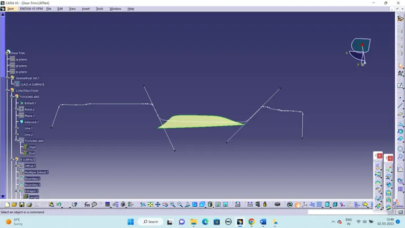
Tooling axis is the direction in which a core or cavity of mold opens. This Axis is very important to determine the orientation of the component in mold, core and cavity design as well as to run the draft analysis of the component.
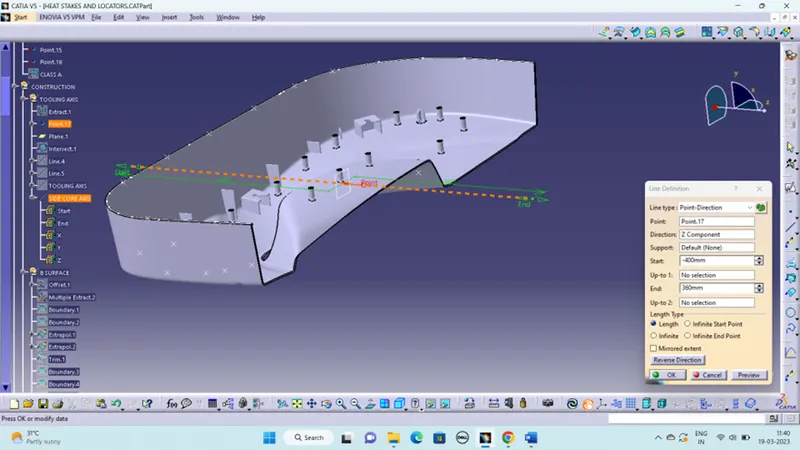
SIDE CORE AXIS:
It is created by the tooling axis point to the Z direction.
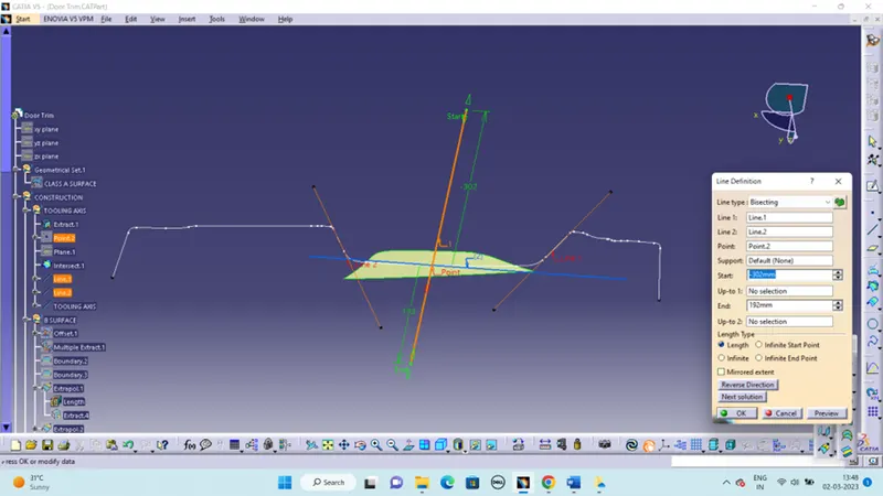
BISECTING METHOD:
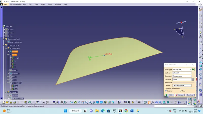
- In this way first I create the point (on surface) in the extracted surface.
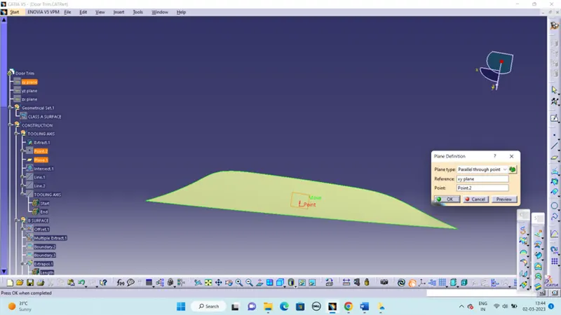
- Then I create the plane for getting the intersection line from the surface.
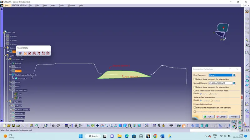
- Then create the line on the intersection line. These two lines is the key to create the bisecting line and which is going to our tooling axis.
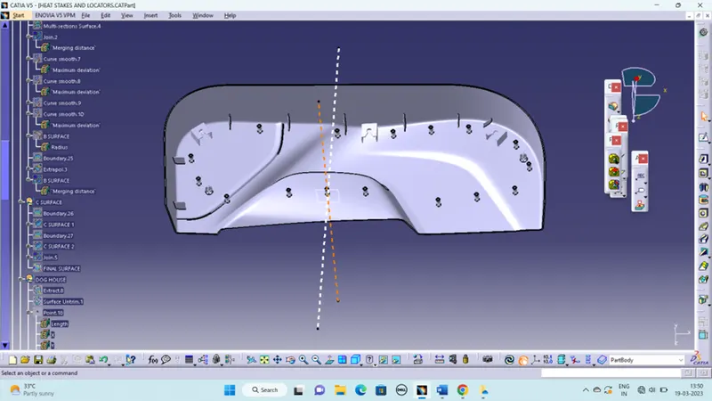
CLASS B SURFACE:
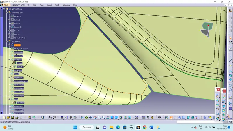
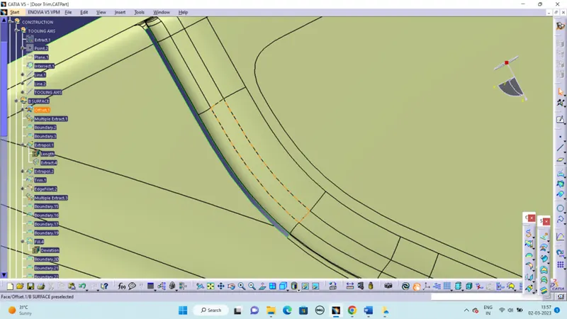
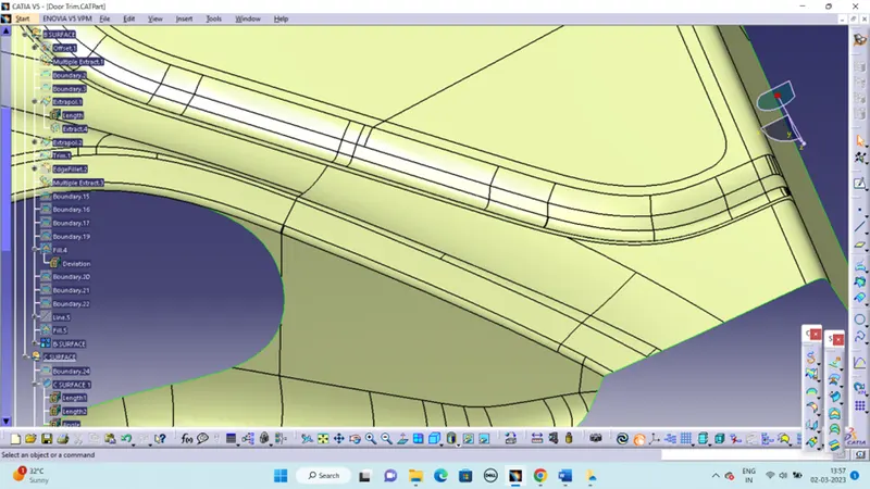
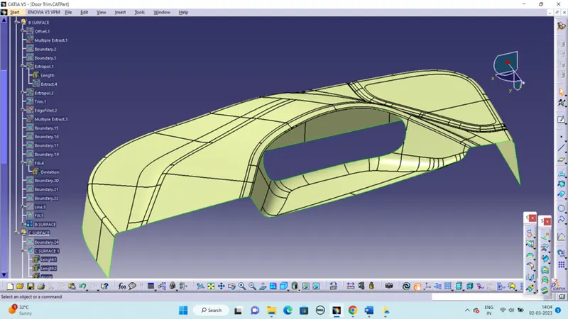
The thickness of the component as 2.5mm. Now we need to create a B surface which will be similar to the A surface at an offset value of 2.5mm. there are some discontinuities happened while offsetting the CLASS A surface so I repaired it to form a closed boundary by using the multiple extract, extrapolate, trim and fill surface commands and tools.
FINAL B SURFACE:
C SURFACE:
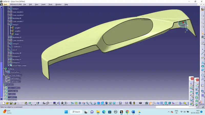
C surface is created with help of A-Surface by using the Sweep(with reference surface) and Boundary command separately, finally joined together to get the final C surface.
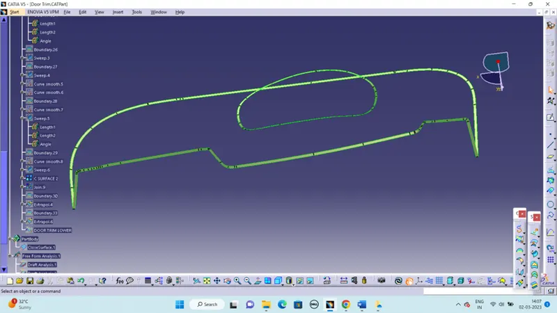
Then join the class A surface to the class C surfaces after that I trim out the joined A and C surface to class B surface to get the final object.
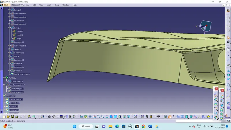
DOOR TRIM LOWER:
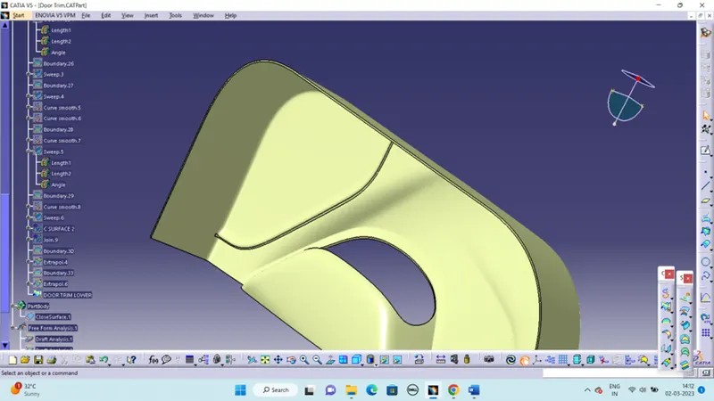
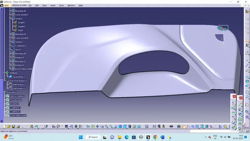
CLOSED SURFACE:
CREATION OF LOCATORS:
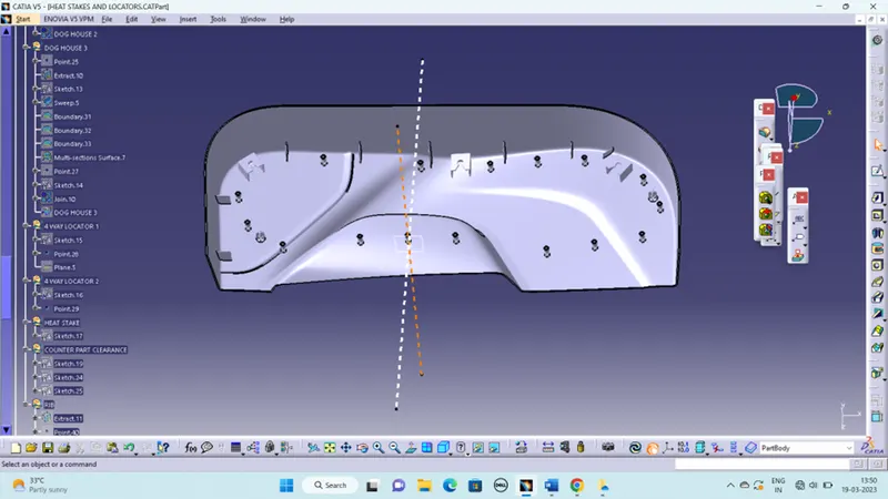
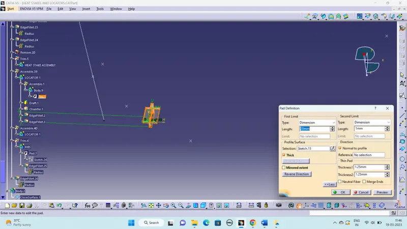
To create the locators, I created a sketch on the body. After creating the sketch, I pad it 20mm in height and thicken it to 1.25mm and I drafted it with 0.5deg in the direction of the tooling axis. I gave 1mm of chamfer with 45deg of inclination and after I gave a fillet of 0.3mm radius.
CREATION OF HEAT STAKES:
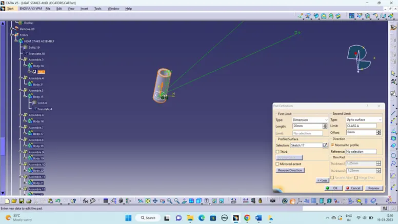
To create the heat stakes, I draw a sketch on the surface. After the creation of the sketch, I pad it to 18mm height and I gave a draft angle of 0.5deg on both sides (inside and outside) and then I gave a fillet with a 0.3mm and 1mm radius. After creating the heat stake, I created the ribs for supporting purposes. To create the ribs, I draw a sketch and padded it to 12mm in height and 1mm in thickness. After padding the ribs, I drafted 0.5deg in the tooling axis direction and filleted it with a 0.25mm radius. Finally, I union trim the ribs with a heat stake to remove the ribs, which are present inside the heat stakes.
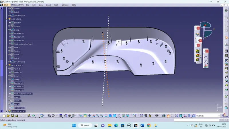
DOG HOUSE
Dog house is an engineering feature used in plastic design. Dog houses are used as support feature. Sometimes other engineering features like snaps, locators, screw bosses are mounted on them to increase their strength.
Dog houses are subjected to draft analysis to prevent breakage of the component during ejection from the mould cavity. Dog house and oher engineering components are built on the B-surface
- Dog houses are designed to avoid SINK MARK created on the CLASS-A surface by screw bosses and to solve the length issues when giving screw bosses which need to be assembled to other components.
- It is also useful when perpendicular screw bosses are required on the part to the tooling direction.
- Make a rectangle to enclose the screw boss in it but make sure it is open from one side.
- Sweep it with tooling axis as the pulling direction inwards.
- Close the top face by using multi section surface.
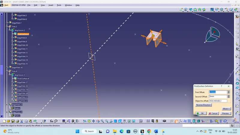
- Thicken it by 2.5 mm to the outward direction.
COUNTER BORE CLEARANCE:
RIB CREATION:
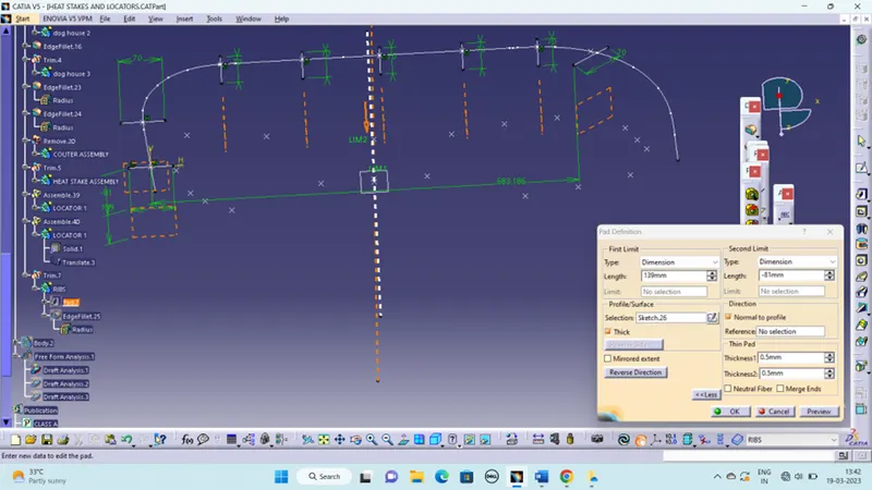
Ribs are thin wall protrusions that extend perpendicularly from a wall or plane. They are usually found in clusters offering support to a plane that would have otherwise been too thick, but can also be stand-alone support for a single wall. They are commonly used to provide additional support and strength to a part. Thickness and location are essential to rib design.
First, the base surface where the rib has to be created is extracted using the Extract command. A positioned sketch is created and the profile for the rib is drawn.
Next, the profile is extruded, to find the height (h) = Wall thickness * 5
=2.5*5
= 12.5 mm
Therefore, the height is 12.5 mm
The extruded surface is thickened,
Thickness(w)=0.4*t
=0.4 * 2.5
=1mm
Therefore, the thickness of the rib is 1 mm
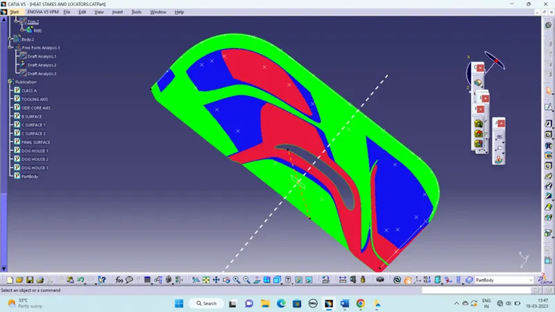
DRAFT ANALYSIS:
FOR FINAL BODY:
FOR CLAS A SURFACE:
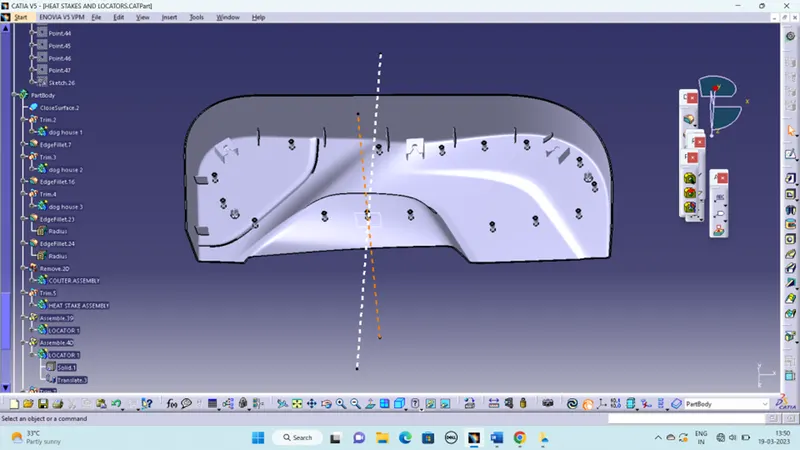
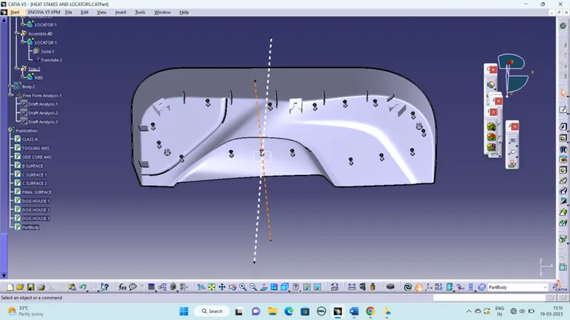
TREE STRUCTURE: