Week 9 - Project_1 - Door Trim Lower with Engineering Features
DOOR TRIM LOWER WITH ENGINEERING FEATURES
To Create the Door trim lower component through the given Class-A surface.
CLASS-A SURFACE CREATION
Class-A surfaces refer to those surfaces that are visible in a product. In other words, class-A surfaces that are visible to us (interior/exterior), and have an optimal aesthetic shape and high surface finish. It is created by the styling team and gives to the part design engineer to create the part with all engineering aspects.
To ensure that the given surface has no gap, We can check it visually and with the help of Join or boundary commands.
Class-A Surface:
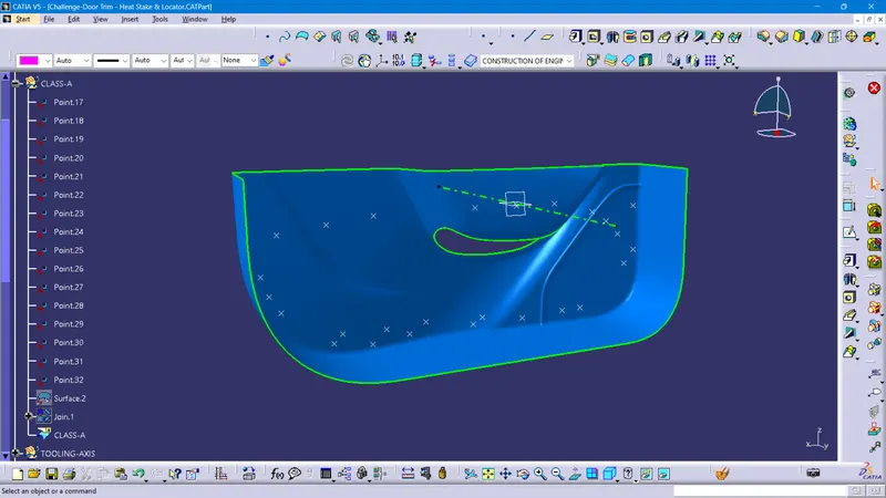
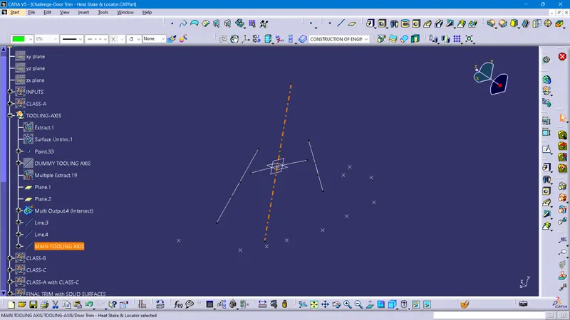
TOOLING-AXIS CREATIONS
First, I extracted the class-A surface to create a point on the surface, also made a plane parallel through the point, made the plane with 'xy axis system', by using the intersection command, take the intersection line to create the line with a bisecting method to perform the draft analysis. accordingly, I made another bisecting line with an opposite side plane
DRAFT ANALYSIS FOR CLASS - A
Change the view to the MATERIAL mode for draft analysis
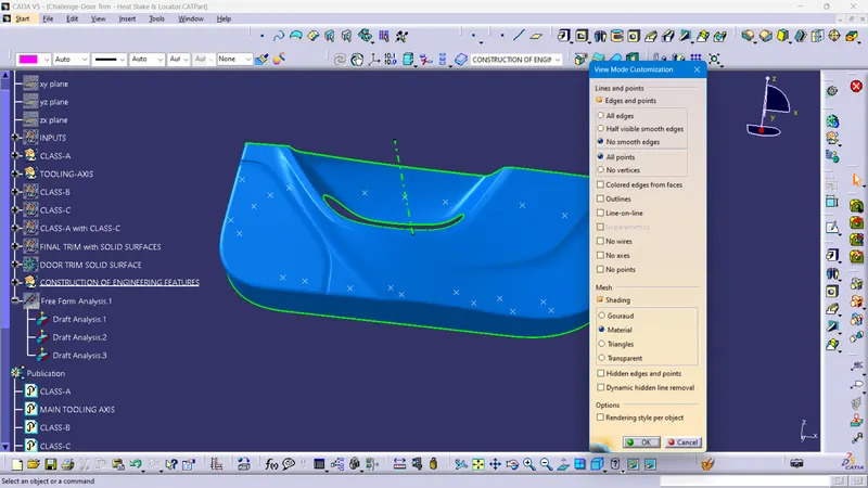
select the compass function to align the compass to the tooling direction and lock the direction using the lock function in the draft analysis toolbar
the surface is showing green color so that the surface clears the minimum draft angle of 0.5 to 3 degrees
Using the analyses under the running point we can check the draft angle on the individual faces. It shows how many drafts are on specific points when we move the cursor point.
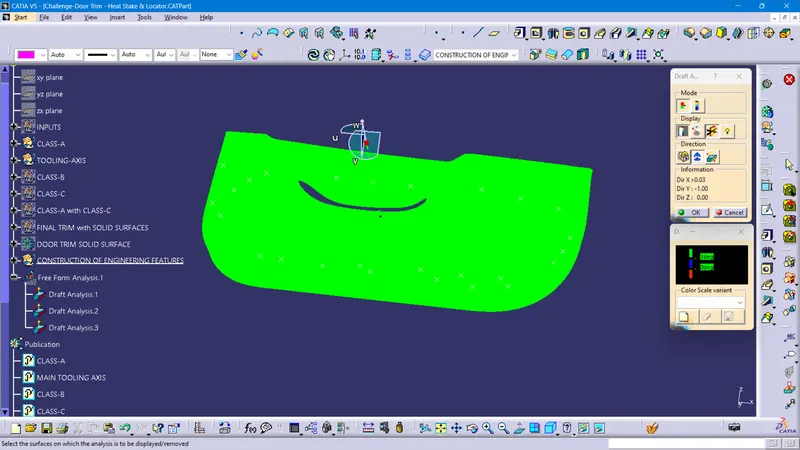
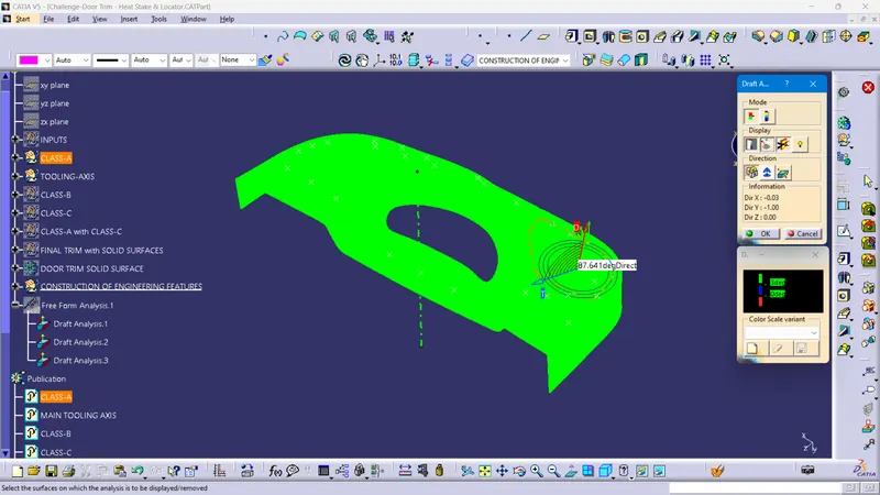
Green color - above 3 degrees positive draft
blue color- below 0 degree
Red color -between 3 and 0
CLASS-B SURFACE CREATION
While offsetting the class-A surfaces to the inward direction, with a 2.5mm thickness of the given plastic parts. I solved the class-B surfaces by finding some gap surfaces, as given below.
Rework the patches and discontinuity of the offset surfaces using the features like extract, multi-extract, sweep, multi-section surfaces, extrapolate, Trim, split, and fillets.
To ensure the continuity of the Class-B surfaces checks the boundary command to find out the boundary.
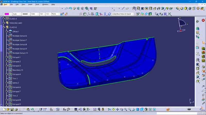
Hence class-B surface creation is done.
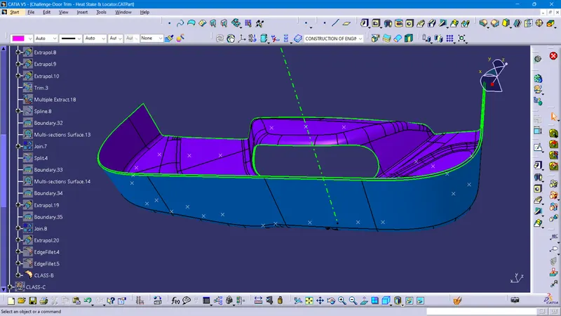
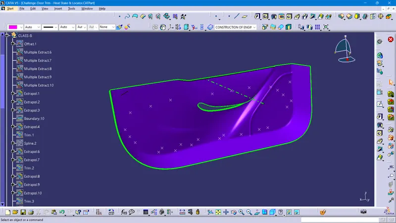
Class B surface offset of 2.5mm is given below:
CLASS-C SURFACE CREATION
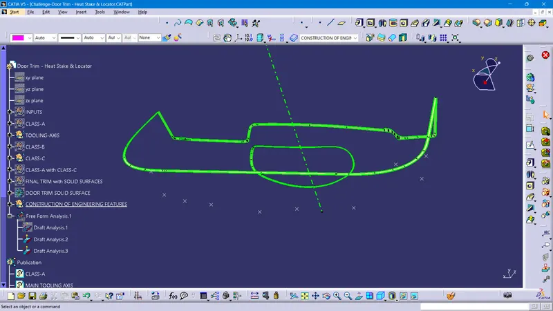
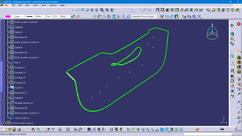
This surface connects the Class A and Class B surfaces. (Surface in between Class A & B surfaces)
Procedure to build Class C surface:
Since it is a complex class-A surface, don't simply create the class-A boundary curve and sweep it in one shot. Hence, we need to create smaller boundaries using the boundary command and then create a sweep of 90 degrees concerning the surface option if the class C should come perpendicular to the tooling axis. Sweeps at the areas where class C should come parallel to the tooling axis should have a 3-degree draft value concerning the tooling axis to pass the draft analysis. Also, at the fillet/curve areas, use a multi-section surface to sweep and complete the class C surface and do the same for class-C hole surfaces.
Join every individual sweep using the join command and for the edges which haven't joined, extrapolate and trim off the sweep surface corners at the required edges.
The Class-C Surface is:
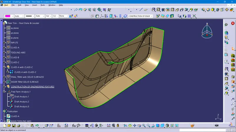
CLASS-A with CLASS-B SURFACES
select and JOIN the CLASS-A-With CLASS-C Surfaces and CLASS-B surfaces
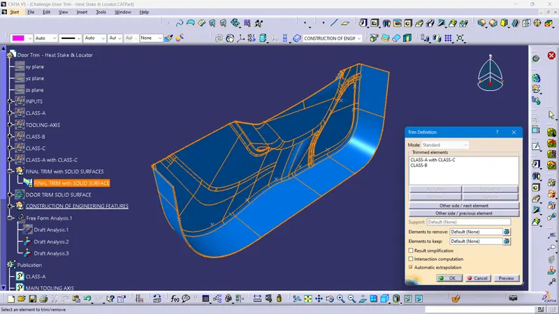
FINAL TRIM TO GET SOLID SURFACES
To perform the final trimming, select and JOIN the CLASS-A-With CLASS-C Surfaces and CLASS-B surfaces
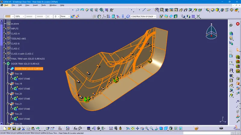
DOOR TRIM SOLID SURFACES
Go to Part design and make the final trim close body.
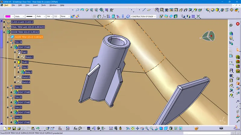
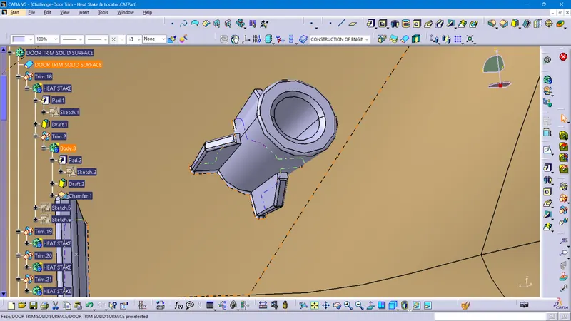
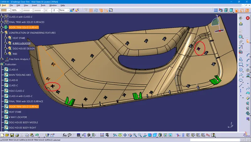
HEAT STAKE DESIGN
Heat Stake features are commonly found in injection molding designs. They are used to aid in the assembly of molded parts by providing a channel for a screw. Their primary use is to strengthen holes or slots in the surface present in the part model.
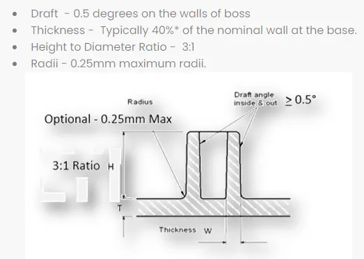
Design rules consider while creating a Heat stake
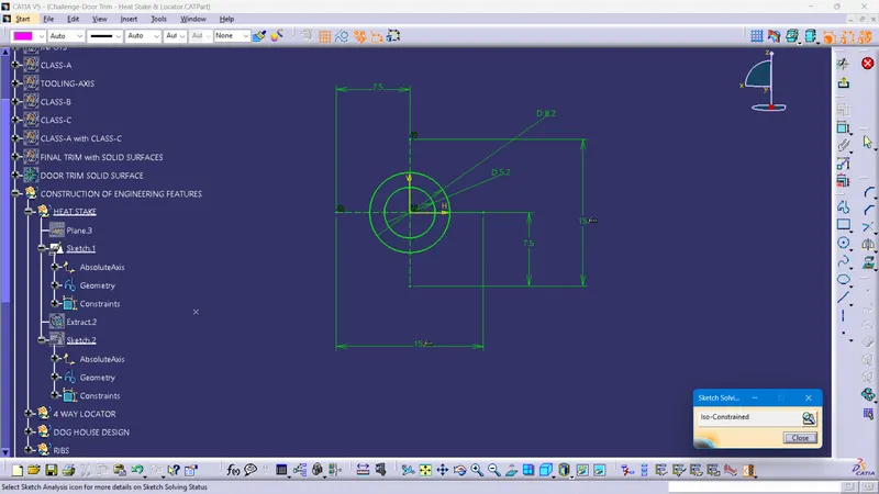
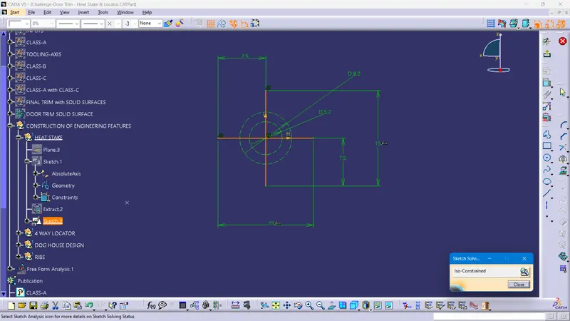
Heat Stake The design begins with the proper geometrical set and uses the positioned sketches to get the screw boss and heat stake sketch
4-WAY LOCATOR CREATION
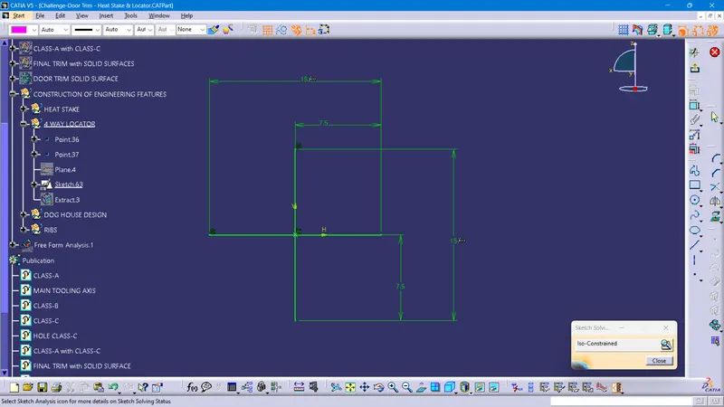
To create the locators, After creating the sketch, pad it 20mm in height and thicken it to 1.3mm and drafted it with 0.5deg in the direction of the tooling axis. 5mm of chamfer with 45deg of inclination and after I gave a fillet of 0.25mm radius.
Sketch Plane is made in the tooling axis direction.
4-way locator:
Height = 20 mm
Wall Thickness = 1.3 mm
Draft Angle = 0.5°
Chamfer = 3 mm, 45°
Fillet 0.3 mm & 3 mm
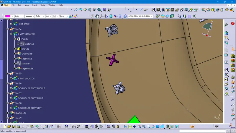
Use copy and paste special to translate them to other locations.
DOG HOUSE DESIGN
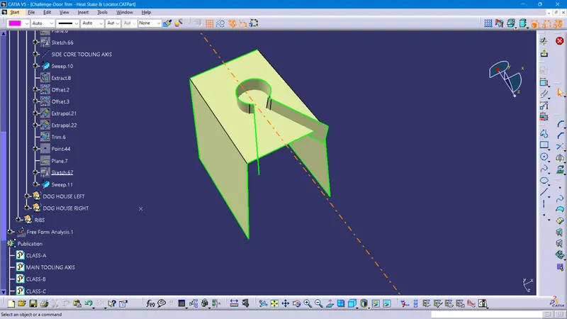
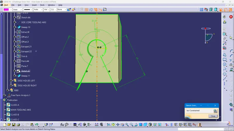
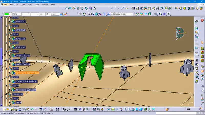
Dog houses are designed to avoid SINK MARK created on the CLASS-A surface by screw bosses and to solve the length issues when giving screw bosses which need to be assembled to other components.
It is also useful when perpendicular screw bosses are required on the part of the tooling direction.
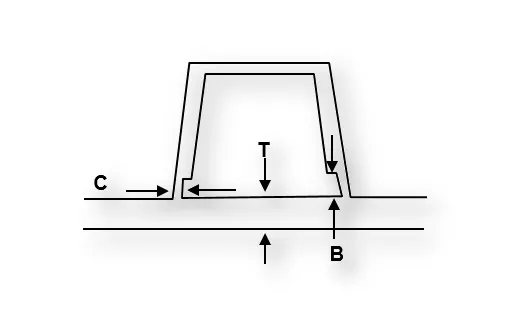
- C thickness should be 40% of the main wall thickness of T
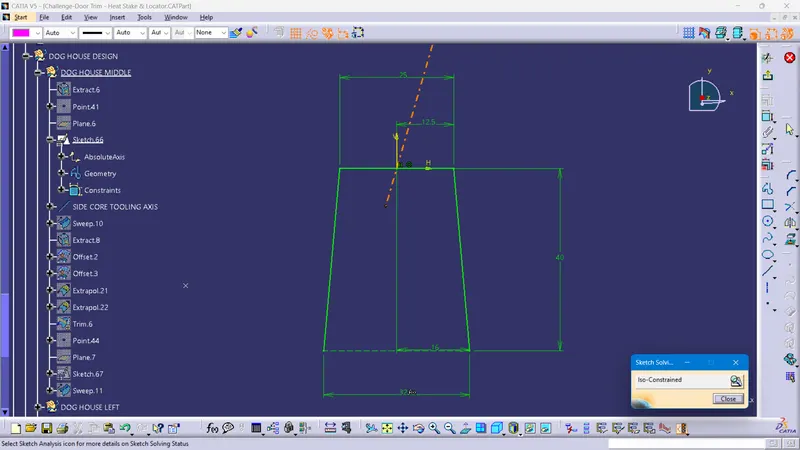
- The minimum width of the dog house is 12 mm.
- The height of B should be 3-6 mm
- The minimum draft for the do house is 1.5 degrees to die draw.
Procedure for creating the DOG HOUSE
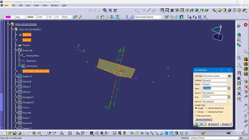
- The first step is to create a side core axis.
- I have chosen normal the point method for creating the side core tooling axis.
SIDE CORE TOOLING AXIS CREATIONS
RIB DESIGN
Ribs are thin wall surfaces that extend perpendicularly from a wall or plane. They are usually found in clusters offering support to a plane that would have otherwise been too thick, but can also be stand-alone support for a single wall. They are commonly used to provide additional support and strength to a part. Thickness and location are essential to rib design.
First, the base surface where the rib has to be created is extracted using the Extract command.
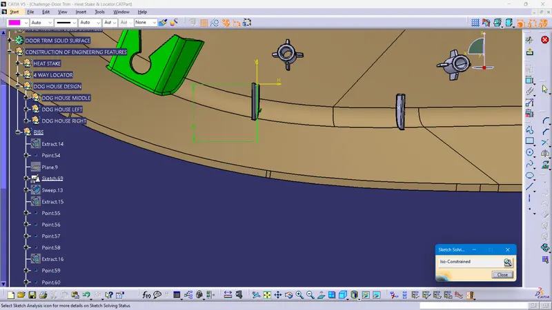
Next, the profile is extruded, to find the height,h=Wall thickness * 5
=2.5*5
= 12.5 mm
Therefore, the height is 12.5 mm
The extruded surface is thickened,
Thickness,w=0.4*t
=0.4 2.5
=1mm
Therefore, the thickness of the rib is 1 mm
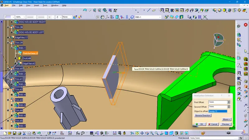
Use copy and paste special to translate them to other locations.
by using the translate command we can relocate to another position as required
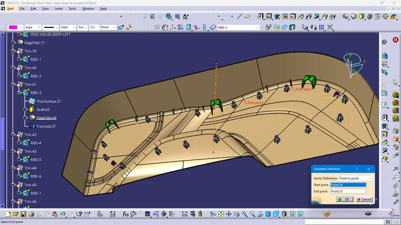
Then fillet is applied to the faces of the rib. As per the design rule, the fillet can be 0.25 mm.
DRAFT ANALYSIS FOR FINAL COMPONENTS
The same procedure for the draft analysis of the CLASS-A surface is followed.
Screenshots of the solid model with the proper color code of the draft angle in various orientations:
analysis of the draft angle minimum for my final component is clear for a 0.4-degree draft angle.
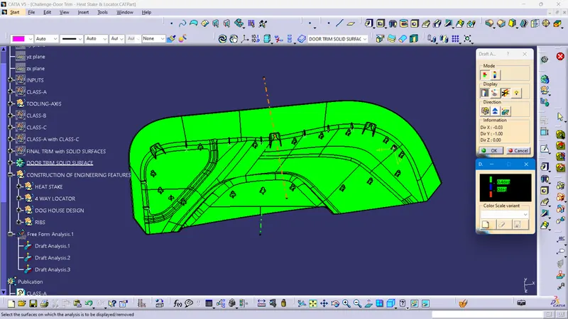
And also the publication of all major operations is identified in an orderly.
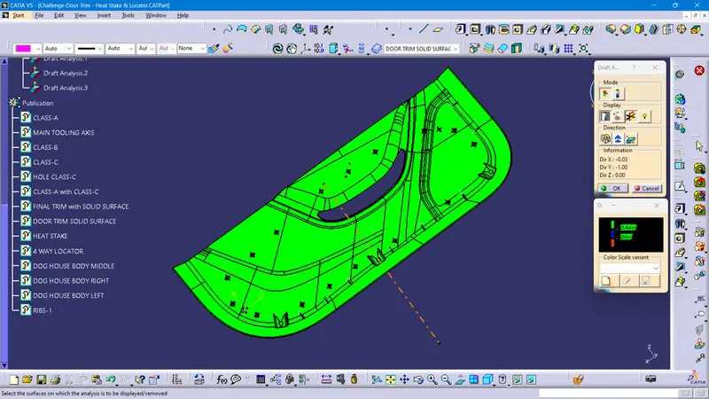
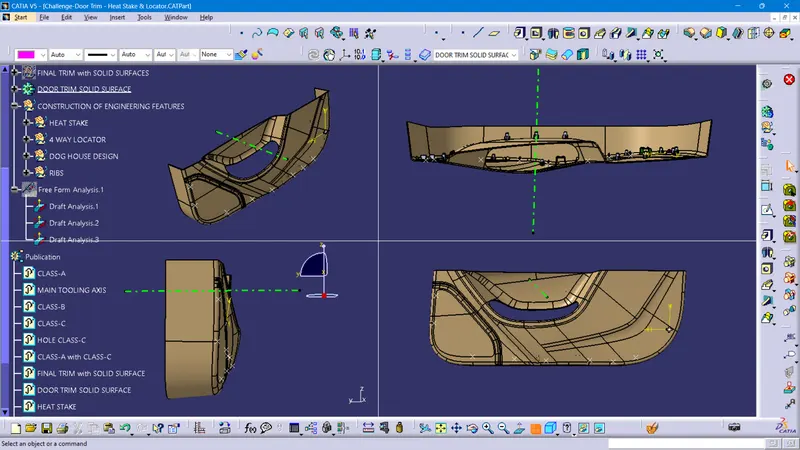
please find the attached file for more details
Thanks
Regards
sathish