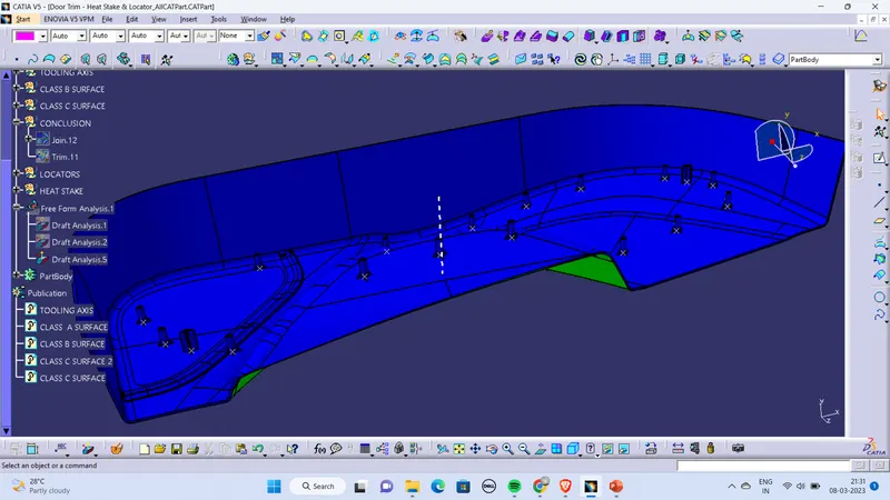
Week 9 - Project_1 - Door Trim Lower with Engineering Features
- Screenshots of the completed design in various orientations (Isometric, Fr
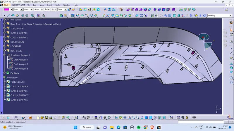
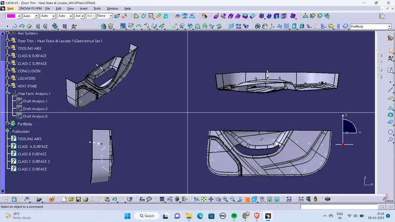
- DRAFT ANALYSIS REPORTS
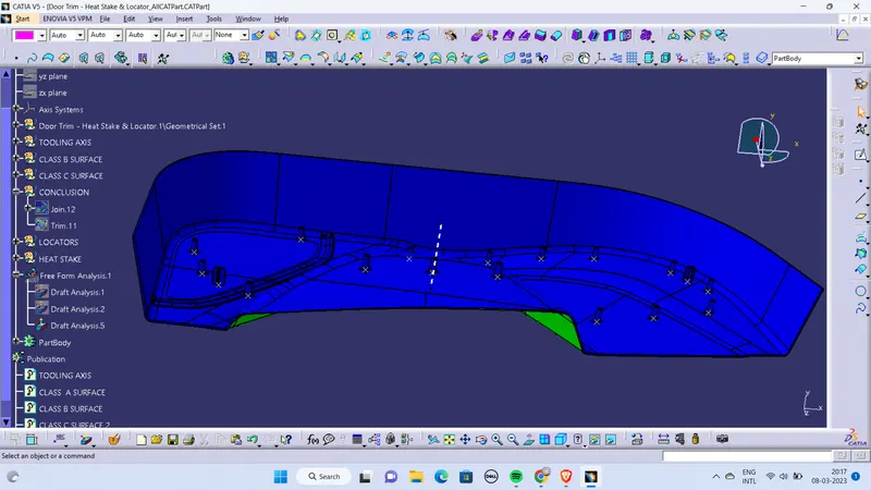
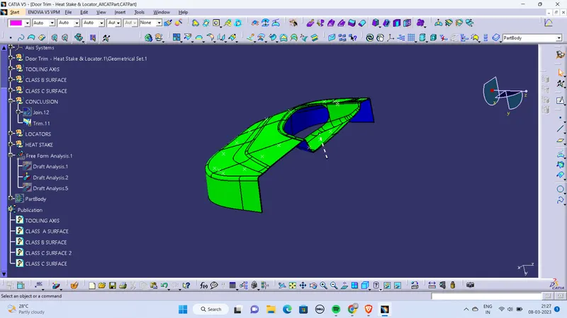
- Detailed report explaining the draft analysis and the tooling axis creation.
-
Draft analysis
The draft analysis in CATIA refers to a tool that allows users to determine if they can remove the part that they are designing from the tool being used to design it.
How to do draft analysis in Catia V5?
Step 1:enter part in Catia
Step 2:Click on the insert
Step 3:Click on analysis
Step 4:click on feature draft analysis
If it says wrong material mode then;
->go to customize view parameters and click on material in shading column
Step 5:click on feature draft analysis
->place the compass on the tooling axis with complete alignment
->And click on the surface; if it shows GREEN – OK
if it shows completely blue – Flip direction
***Make use of the mode,display and direction specifications for fruitful draft analysis
Tooling axis
The Tooling axis is the direction in which mold opens when core and cavity opens (or) simply; In molding machine arrangement is given to open the two halves of the mold along a direction which is known as tooling direction..
METHODS TO FIND MAIN TOOLING DIRECTION:
There are plenty of methods of approach for creating tooling axis and they are:
(i)Along axis Direction(X,Y,Z)
(ii)Normal to face part/feature/environment part features
(iii)Reference from feature/master section
(iv)Trail and Error by compass
(v)BISECTION METHOD
Among all these methods for bumper; NORMAL TO SURFACE METHOD is the more crucial one…
NORMAL TO PLANE SURFACE METHOD:
Step 1:Select a normal and non curved surface and extract it.
Step 2:create a point with zero distance and place a line normal to the point created earlier and it would act as a tooling axis
Step 3: After identifying the tooling axis;
->Make sure the line Is “published” such that it would be visible in tree structure out of geometrical set
->To publish; Go to tools and click on PUBLICATION…