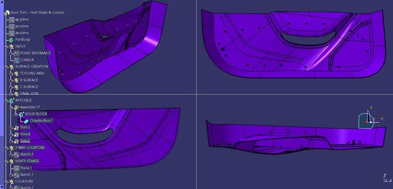
Week 9 - Project 1 - Door Trim Lower with Engineering Features
Aim: To Create the Door trim lower component through the given Class-A surface.
Procedure
class A surface
Tooling Axis creation:
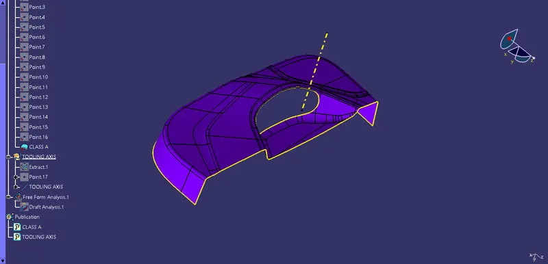
To create a tooling axis, a plane surface from class A is extracted and a point is created on it. Then a line is created through that point in the y direction.
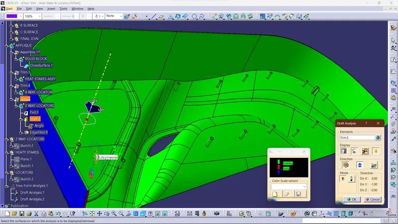
Draft Analysis on class A
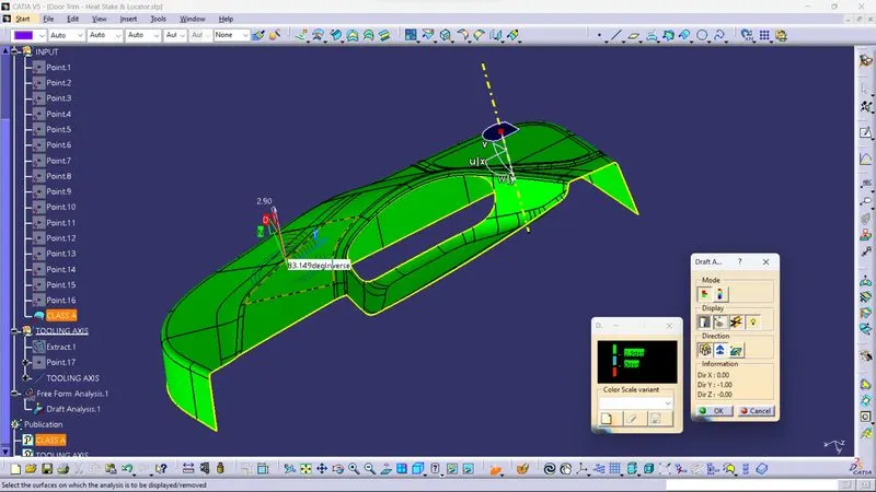
We perform a draft analysis check for class A surface before we make solid and creation of B-side features. Initially we align the compass to the tooling axis and give a 2.5deg draft angle for the green colour in the colour bar. If the surface is highlighted in green colour the draft angle is given properly for class A surface. If the class A surface is not highlighted fully in green colour, that might be the reason for the draft angle of the class A surface.
CLASS B SURFACE:
Class B is created by offsetting class A in the downward direction at a distance of 2.5. Once the offset is created, we may see some patches on the offset surface by taking the boundary for the offset surface, those patches are formed due to the fillets on the class A surface. We need to cover those patches with the help of the multi-section surfaces command by extracting the patch boundaries. Once all the patches on the offset are covered properly join all the patches with the offset surface, to get the replicated surface of the class A surface.
CLASS C SURFACE:
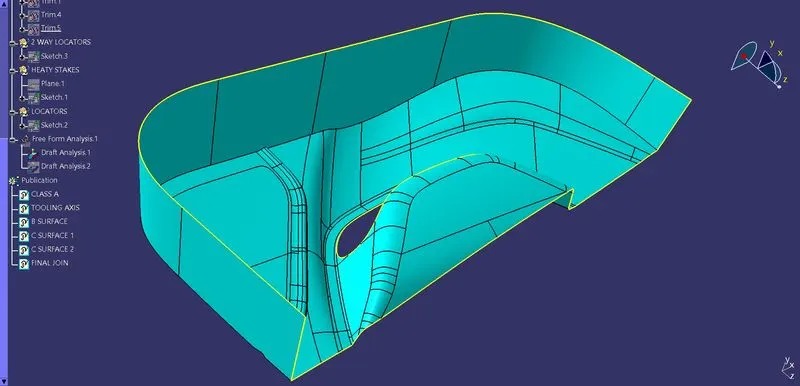
We use the sweep command to create the class C surface concerning the boundary of the class A surface. We extract the boundary of the class A surface with tangent continuity and I sweep the extracted boundary concerning the surface at 93deg for draft angle.
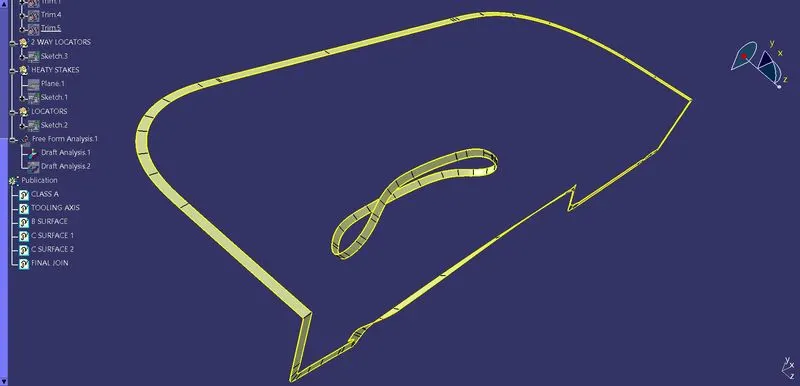
Now, join both class A and sweep the boundary to get the complete class C surface.
CREATION OF LOCATORS:
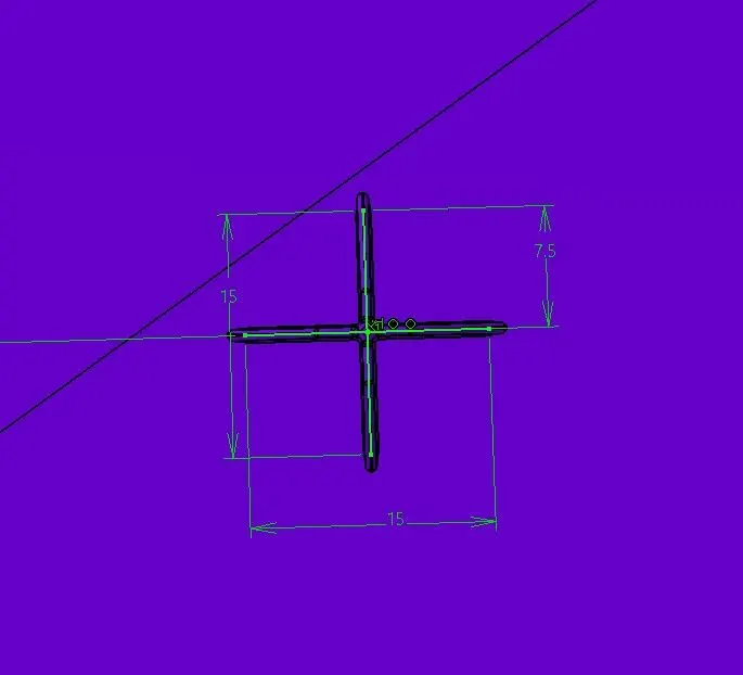
4-way locator:
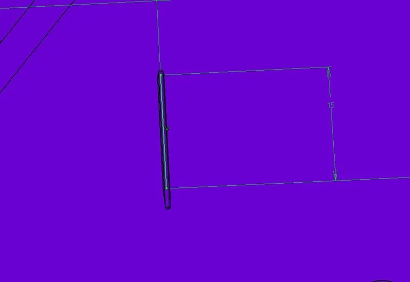
2-way locator:
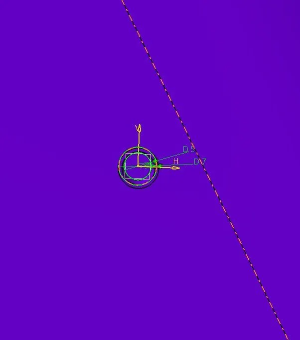
HEAT STAKES:
DRAFT ANALYSIS FOR PART BODY:
FINAL BODY