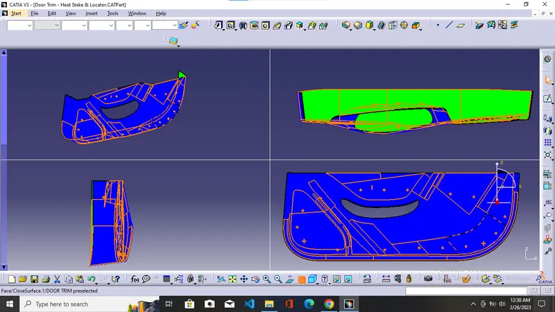
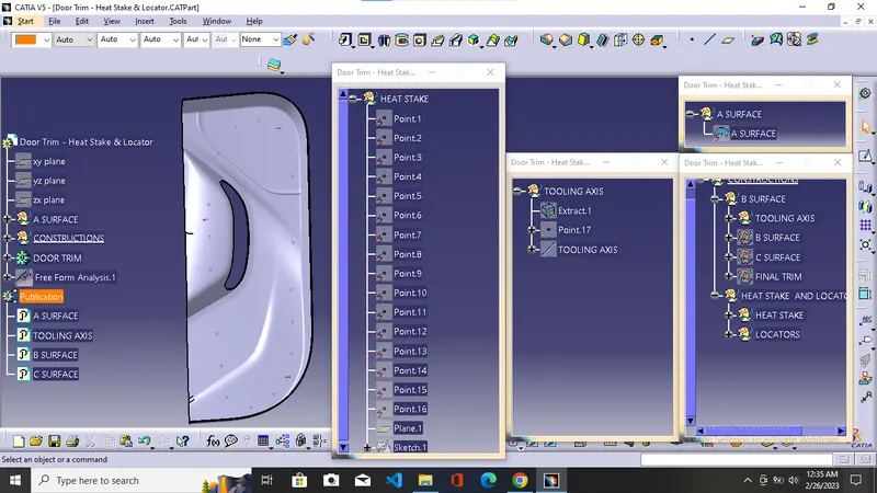
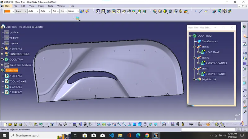
Week 9 - Project 1 - Door Trim Lower with Engineering Features
ans 1
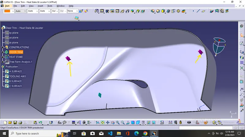
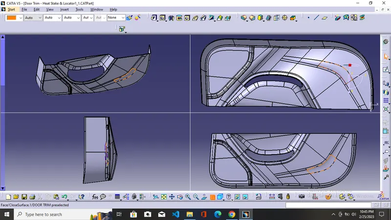
TOOLING AXIS = It is the axis or direction along which the core and cavity move and the required part ejected along this direction. In this question, we are going to explain making tooling axis by THE POINT AND DIRECTION method.
STEP 1 =Selecting the surface along which we need to create the tooling axis.
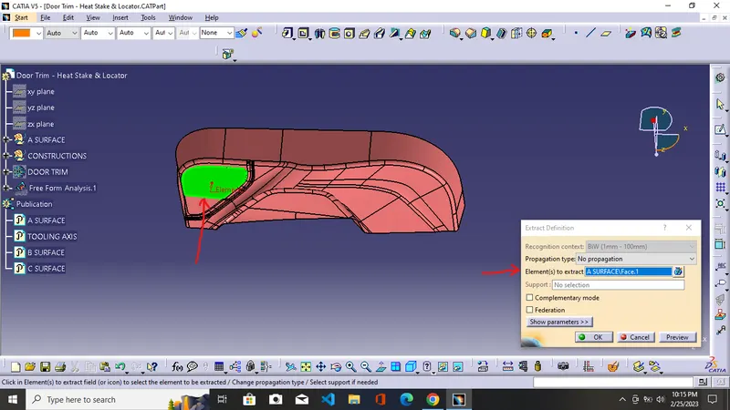
STEP 2 = Creation of point using the point tool using the option on the surface. select the extracted surface and give 0mm in the distance option to create the point in the middle of the surface.
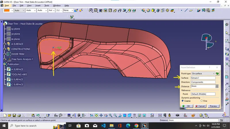
STEP 3 = Creation of the required tooling axis using the line tool and selecting the point and direction option to give extracted surface in the reference surface option and the previously created point in the reference point option and obtain the required tooling axis.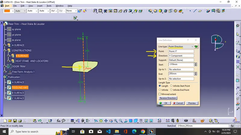
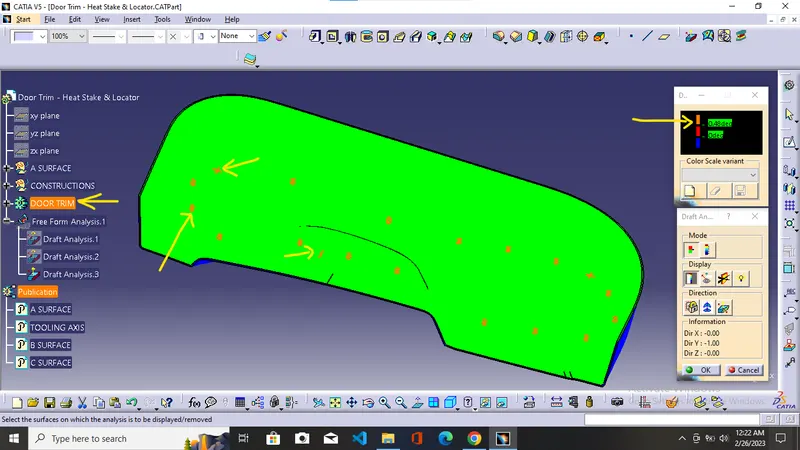
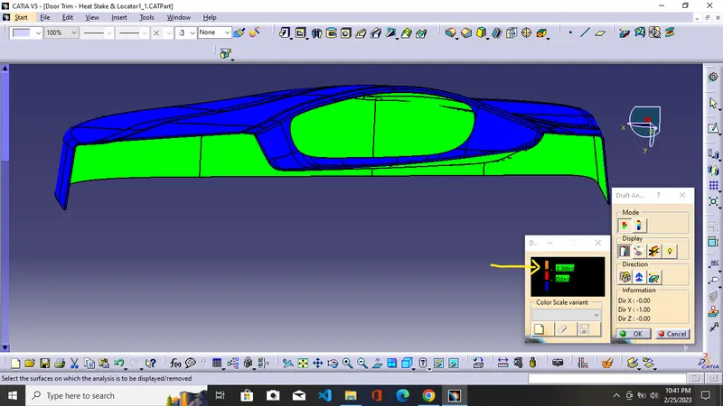
DRAFT ANALYSIS = It gives us information about the parts which tells us which part clears the mold walls easily so as to minimize the machining process in the finished product and final product ejected easily and minimize the contact between the product and mold walls.
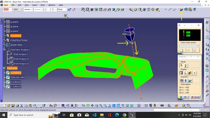
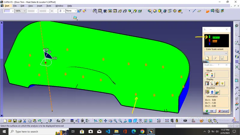
STEP 1 = Select the Feature draft analysis tool and move the compass to the tooling direction and align the compass w axis to the tooling axis. After aligning the compass with the tooling direction again click the compass tool to insure the proper alignment of the w-axis with the tooling axis. After the proper alignment uses the locking tool to lock the compass with the tooling axis.
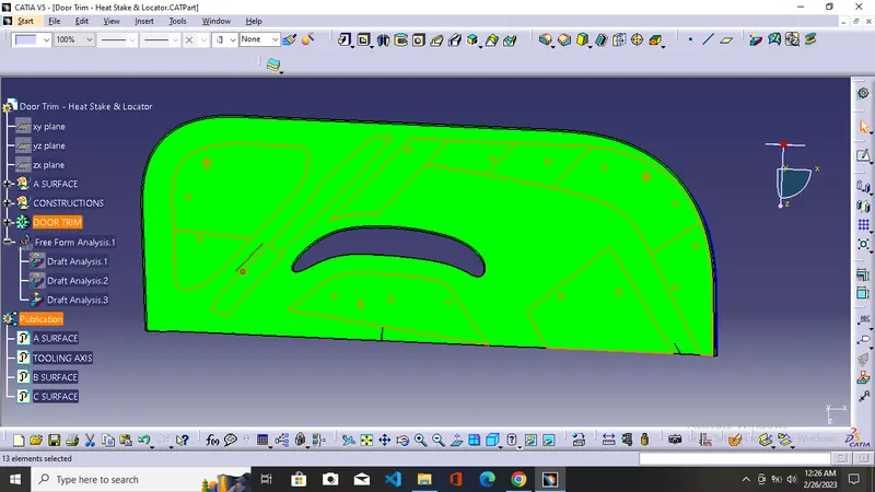
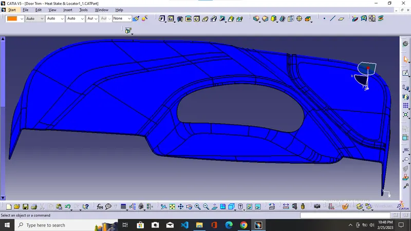
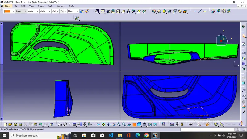
STEP 2 = Click anywhere on the A surface to generate the draft analysis report and use the quick analysis mode option to see the color code values where the green color defines the parts which have a draft angle greater than the green color code value generally it is up to 3 degrees in values. The red color gives information about the parts which have angles between 0 to up to a green color value which is generally up to degrees. The blue color gives information about parts that have an angle less than the red color. If A surface comes out in green color means our tooling axis is perfect and we are ready to go for the formation of B and C surfaces.
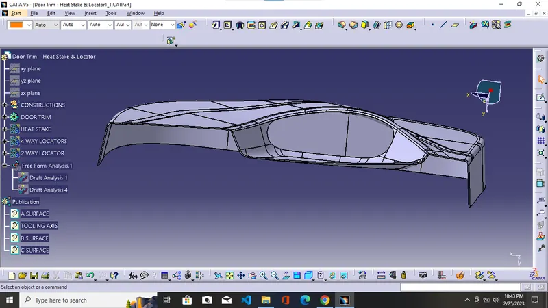
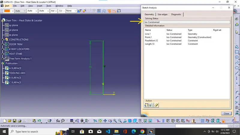
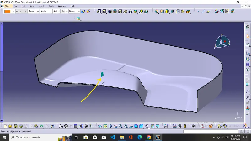
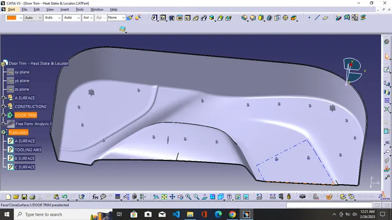
HEAT STAKE = It is an engineering feature that serves as a joint between the two components. The process by which the heat stake joins the two components are known as Heat staking. In heat staking, we use local heating and cooling to raise the temperature of plastic components and allow plastic reforming to be carried out. 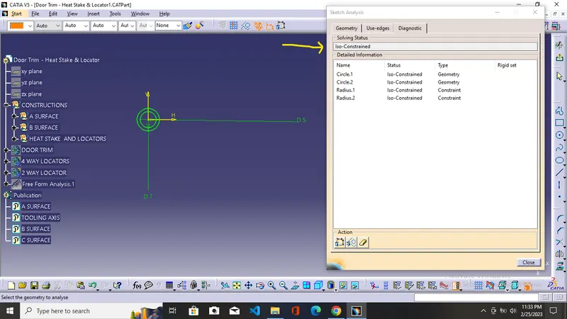
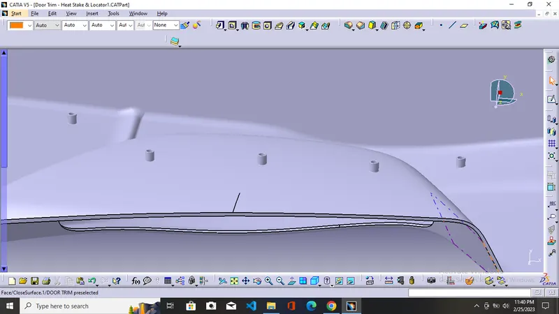
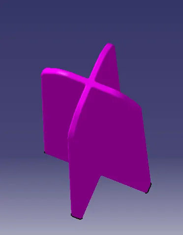
NOTE = Some heat stakes are also made with cross ribs to support the heat stake if the heat stake has a longer height to prevent it from buckling under the load. But here the height does not cross the maximum height limit so we do not require the cross ribs support with a heat stake.
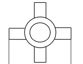
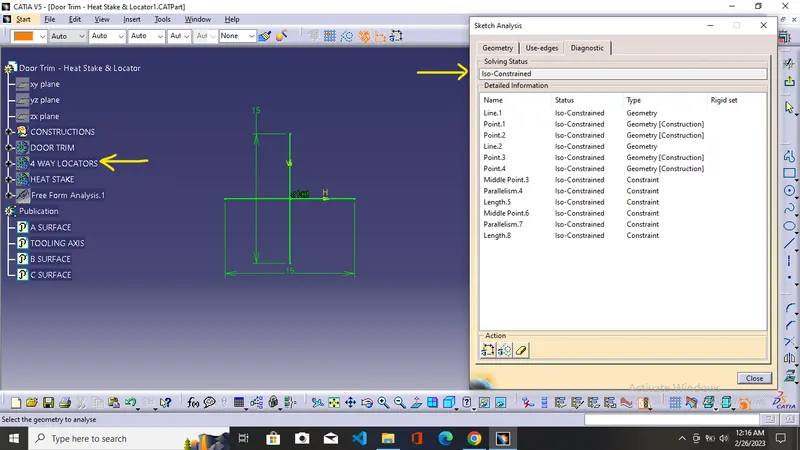
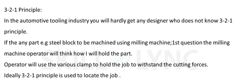
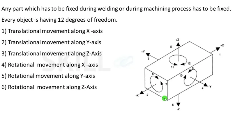
LOCATORS = Before joining the two components we need to fix and properly align the component in that we need the locators. To get the precise or desired movements we need to arrest the undesired movements in the part for the desired result. For that, we use the 3-2-1 principle.
There are two types of locators which are:
4-way locator
2-way locator