Week 9 - Project 1 - Door Trim Lower with Engineering Features
Task:
Create the Door Trim Lower Plastic component through the given Class-A surface. To begin with, the tooling axis for the given Class-A Surface should be created meeting the requirements of the draft angle and at the end perform the Draft analysis on the model.
Create the Heat Stakes and the locators considering the design rules mentioned in the video for the door applique.
Explainations :
Class A :
in this challeges we got the catia part file which is having the A class surface we only change their name and color before that look all body is pefectly close as well as no any impurity in surface
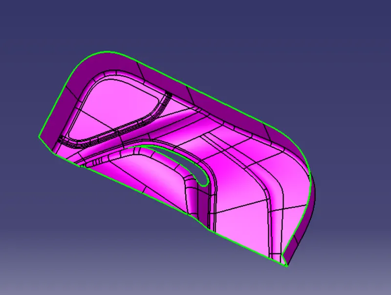
after that we goto develop or create the B surfaces
Procedure Creatation of Toolinf Axis, B surfaces , C surface & Close Surface :
Tooling Axis :
here first we required tooling axis for draft analysis. tooling axis is works as provided to direction for injection moulding as well as direction of draft angle where is check it right or wrong so 1st we extract the surface of class A and than create point on it use this point we create the line by using line command for proper direction which want to the draft analysis and this line knows as the tooling axis
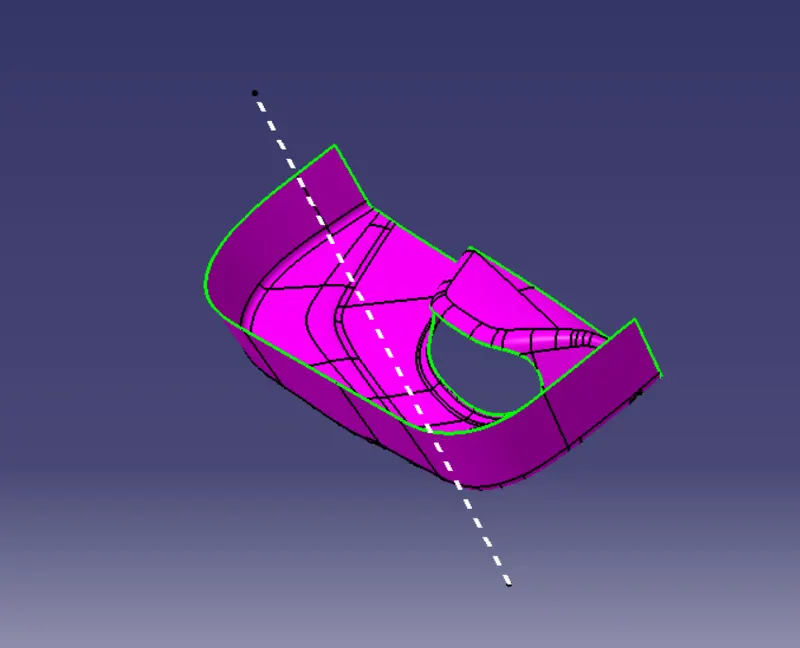
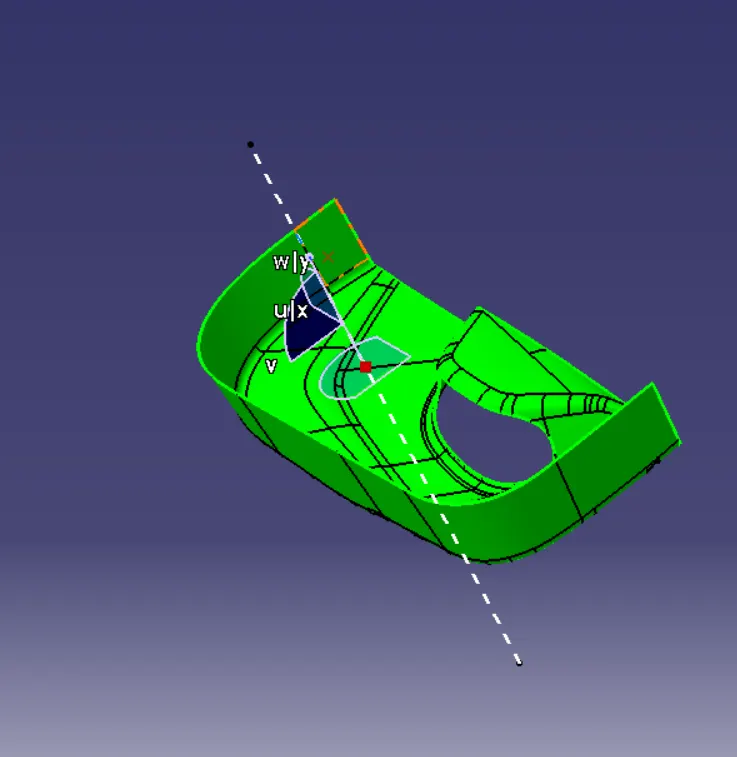
above figure show the tooling axis and checkt this axis direction is right or not we just click on draft analysis and fix compass on tooling axis than click on surface and we get green color for all surface so that tooling axis direction is right shown as below image
B surface :
here we just offset the Class A surface and get the B surface body here we offeset the 2.5mm value so we get the thickness is 2.5mm is mention in above so we offset the A surface for 2.5mm
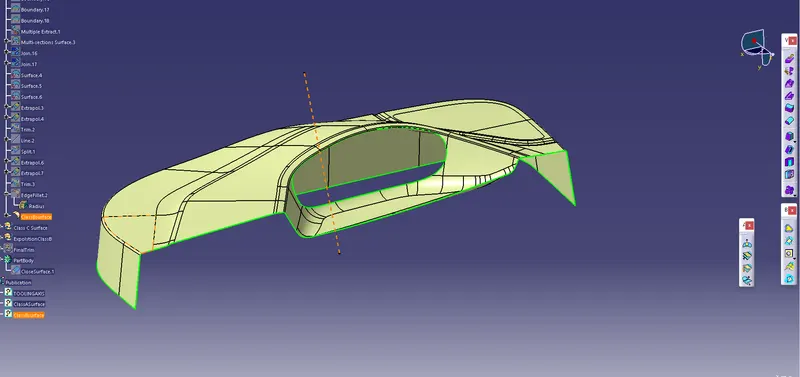
after the offset we get the surface but in that some impurities some portion not offset so we required to solve it so used explore, multiple extract, fill, curve conect, join command and get desire output mobel no any discontinuty than color it so we get B surfaces
C surface :
c surface creation by using the sweep command so 1st we create a boundary than disassemble get two curve 1st out-side surfaces than second is in-side surfaces after that we used sweep commat in that goto draft section on choose surface reference option and sweep it similar think done inner curve than we get c surface
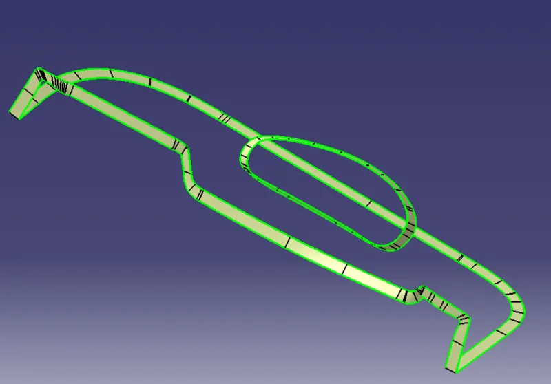
above figure show c surfaces than we join with A class surface we get final output of C-surfaces as shown in below
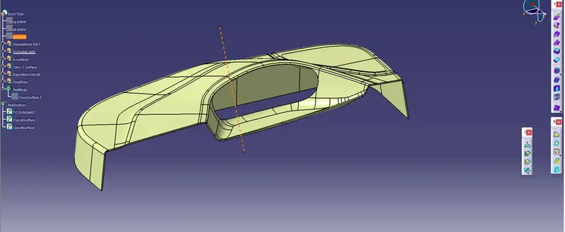
after that we goto the close surfaces
Close Surface :
close surface get the by trim final surface of c class shown in above image with the b class surface in that we required condition to properly trim it so we used exploer command and exploer B surface required dimension same think done both inner and outer curve than trim it get close surface
after that we get solid body by using close surface command on part design section
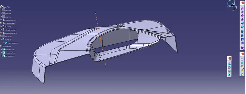
after that we published all thinks which explain in above
Procedure of Draft Analysis :
here we goto the draft ananlysis and 1stly we required direction so used tooling axis so we drag the compass and properly mounting on tooling axis than fix it after that goto analysis and get the results
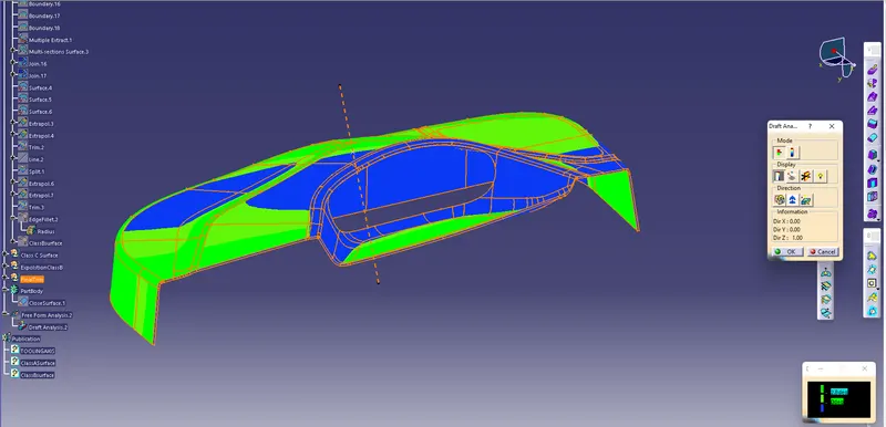
here we see that green means draft angle greater than the required angle value and above figure shows the draft analysis results.
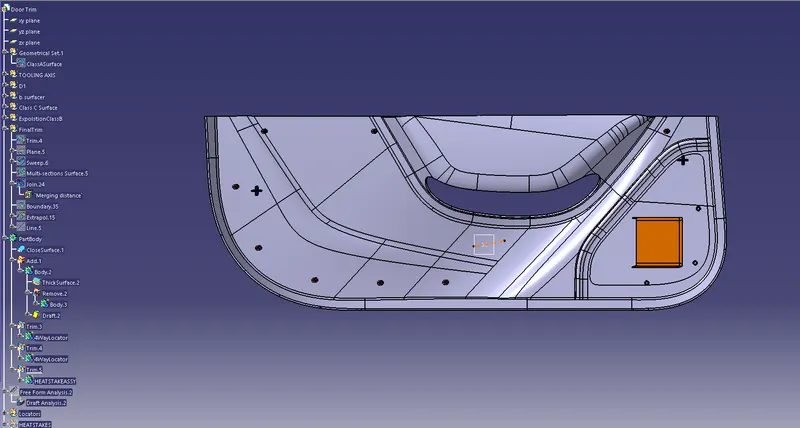
DOOR TRIM WITH LOCATORS AND HEAT STAKES :
DESIGN OF 4 WAY LOCATORS :
I took a gemoetrical set and i had drawn a sketch with reference of plane and projection point, after i given PAD for the sketch with in the dimension limits as, with NEUTRAL FIBER.
THICKNESS = 1.3
I had given a DRAFT = 0.5, and given a fillet on the locators side,
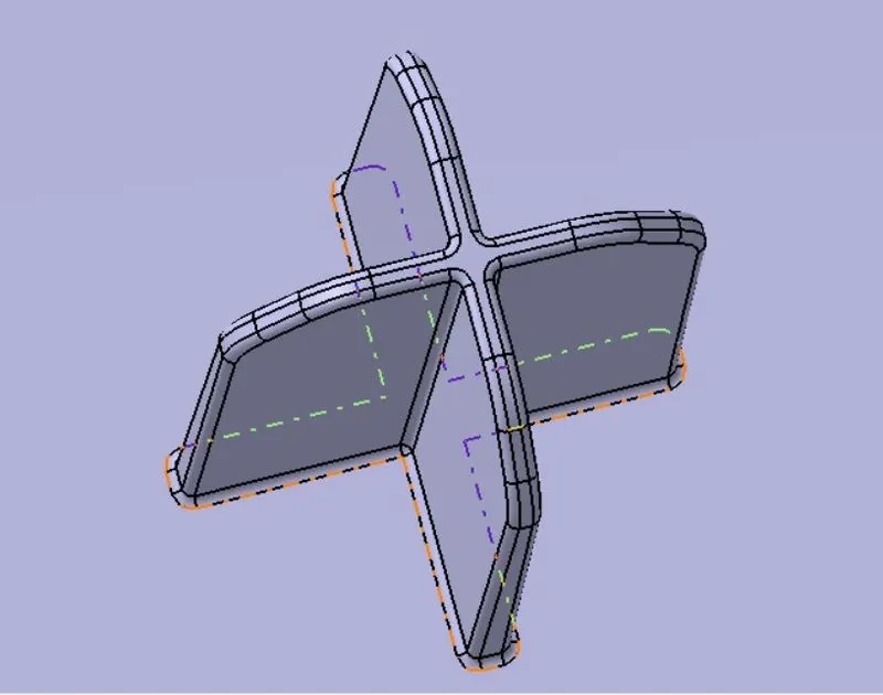
SIMMILARLY HAD MADE ANOTHER 4 WAY LOCATOR ON OTHER SIDE AS PER THE MODEL SHOWN IN THE QUESTION
DESIGN OF HEAT STAKES WITH RIBS :
I took a gemoetrical set and i had drawn a sketch with reference of plane and projection point, after i given PAD for the sketch with in the dimension limits as, with NEUTRAL FIBER.
I had given a DRAFT = 0.5, and given a fillet on the locators side,
Draft Analysis on the final component :
1. The part created has to be changed to the material mode in the display frame.
2. Compass is enabled and aligns it along with the tooling direction.
3. The lock command is then applied to fix the compass along with the tooling axis.
4. Color codes are classified and Draft angle is applied.
5. Running point analysis is used to display permissible draft angles.
DRAFT ANALYSIS OF THE LOCATORS AND HEAT STAKES :--
THE DRAFT ANGLE FOR HEAT STAKES AND LOCATORS IS 0.5deg.
Overall Diagram:
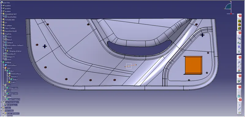
Isometric:
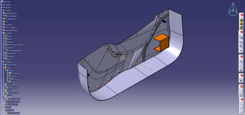
Front view:
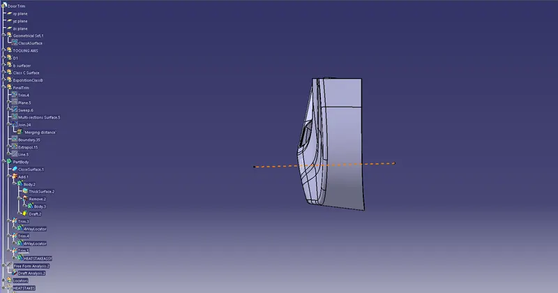
Side View:
Conclusion:
Thus the Door Trim Lower Plastic component through the given Class-A surface With heat stake and Locators are created.